1
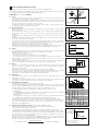
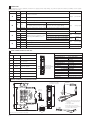
www.atos.com
Table G030-5/E
Digital electronic E-BM-AS drivers
DIN-rail panel format, for proportional valves without transducer
E-BM-AS
C
Digital drivers supply and control the current to the solenoid of Atos proportional
valves without transducer, according to
the electronic reference input signal. The
solenoid proportionally transforms the current into a force, acting on the valve
spool or poppet, against a reacting
spring, thus providing the hydraulic regulation.
E-BM-AS can drive up to two single or
one double solenoid proportional valves.
Electrical Features:
• 4 fast plug-in connectors • RJ45 connector for RS232 Serial
communication to program the driver
with the Atos PC software
• 4 leds for diagnostics : power supply presence, driver status, solenoid
status (S1 and S2)
• ±5 VDC output supply for external reference potentiometers (/P option)
• Electrical protection against reverse
polarity of power supply
• Plastic box with IP20 protection degree
and standard DIN-rail mounting
• CE mark according to EMC directive
Software Features:
• Setting of valve’s functional parameters: bias, scale, ramps, dither
• Linearization function for the hydraulic
regulation
• 2 selectable modes for electronic reference signal: external analog input or
internal generation
• Max power limitation (/W option)
• Selectable range of electronic reference analog inputs: voltage or current
• Complete diagnostics of driver status,
solenoid and driver fault conditions
• Intuitive graphic interface
Internal
Rererence
Generator
D
POWER
STATUS
Enhanced
Diagnostic
S1
S2
Hydraulic
Power
Limitation
(option /W)
E-BM-AS
B
A
Scale
Bias
Ramps
Linearization
E-SW-PS
programming software
MODEL CODE
S - PS - 01H / *
- A
E-BM
Electronic driver in DIN
rail panel format
Options, see section 5 :
- = standard 24 VDC power supply
12 = 12 VDC power supply
A = max current limitation for ex-proof valves
P = electrical supply for external potentiometers to generate reference signal
W = power limitation function (see 6.7)
A = driver for valves
without transducer
S = digital execution
PS = Serial communication interface
01H = for single solenoid proportional valves
05H = for double solenoid or two single solenoid
proportional valves
BLOCK DIAGRAM
LE
DS
:
2
*
Series number
Electronic
reference
input signals
CMD1
RS232
CONNECTOR
1
CMD-
2
CMD2
3
DGND
4
Current
supply to
solenoids
ON/OFF
inputs
RJ45
B
C
MICROCONTROLLER
REFERENCE
GENERATOR
LOGIC
REFERENCE S1
A
SCALE
BIAS
LINEARIZ.
DC/DC
CONVERTER
RAMPS
4
3
1
DI1
2
DI2
3
DI3
4
DI4
REFERENCE S2
D
1
2
1
CURRENT TO
SOLENOID S2
SO
LE
NO
ID
SO
S2
LE
NO
ID
DR
S1
IV
ER
ST
AT
PO
US
W
ER
SU
PP
LY
1
SCALE
BIAS
LINEARIZ.
RAMPS
CURRENT TO
SOLENOID S1
POWER
SUPPLY V+
2
POWER GND
3
ENABLE input
4
STATUS output
EARTH
Only for 05H version
VALVE’S ELECTRICAL CONNECTORS
SINGLE SOLENOID VALVE
TWO SINGLE SOLENOID VALVES
DOUBLE SOLENOID VALVE
01H
05H
05H
G030
3
MAIN CHARACTERISTICS
Power supply (see 4.1)
Max power consumption
Current supplied to solenoids
Reference input signal (see 4.2)
Standard
Nominal: +24 VDC
Rectified and filtered: VRMS = 20 ÷ 32 VMAX (ripple max 10 % VPP)
option /12 Nominal: +12 VDC
Rectified and filtered: VRMS = 10 ÷ 14 VMAX (ripple max 10 % VPP)
50 W for 01H version and for 05H version if drive double solenoid valve
100 W for 05H version if drive two single solenoid valves
IMAX = 2.7 A with +24 VDC power supply to drive standard proportional valves (3,2 W solenoid)
IMAX = 3.3 A with +12 VDC power supply to drive proportional valves with /6 option (2,1 W solenoid)
IMAX = 2.5 A with +24 VDC power supply to drive ex-proof proportional valves (3,2 W solenoid) for /A option
Voltage:
Current:
range ±10 VDC
range ±20 mA
Input impedance:
Input impedance:
Ri > 50 kW
Ri = 500 W
Enable and ON/OFF inputs (see 4.5, 4.7) Range : 0 ÷ 24 VDC ( OFF state: 0 ÷ 5 VDC ; ON state: 9 ÷ 24 VDC ) Input impedance:
±5 VDC @ max 10 mA : output supply for external potentiometers (only for /P option)
Output supply (see 4.4)
Ri > 10 kW ;
Status output (see 4.6)
Output range :
Alarms
Solenoid not connected, short circuit and cable break with current reference signal
Format
Plastic box ; IP20 protection degree ; L 35 - H 7,5 mm rail mounting as per EN60715
Operating temperature
-20 ÷ +60 °C (-20 ÷ +40 °C for 05H version if drive two single solenoid proportional valves; storage -25 ÷ +85 °C)
Mass
130 g
Additional characteristics
Short circuit protection of current output to solenoids; protection against reverse polarity of power supply
Electromagnetic compatibility (EMC)
According to Directive 2004/108/CE - Immunity: EN 61000-6-2 (2005); Emission: EN 61000-6-4 (2001)
Communication interface
RS232 serial connection (not insulated), Atos protocol with ASCII coding (see section 5)
Recommended wiring cable
LiYCY shielded cables:
4
4.1
4.2
4.3
4.4
0 ÷ 24 VDC ( ON state > [power supply - 2 V] ; OFF state < 1 V ) @ max 1,4 A
0,5 mm2 for length up to 40 m [1,5 mm2 for power supply and solenoids]
SIGNALS SPECIFICATIONS
Power supply
The power supply must be appropriately stabilized or rectified and filtered: apply at least a 10000 mF/40 V capacitance to single phase rectifiers or a
4700 mF/40 V capacitance to three phase rectifiers.
A safety fuse is required in series to each driver power supply: 2,5 A fuse for 01H version and for 05H version if drive double solenoid valve
5 A fuse for 05H version if drive two single solenoid valves
Option /12: This driver execution is designed to receive a 12 VDC power supply and it is commonly used in mobile application.
A safety fuse is required in series to each driver power supply: 4 A fuse for 01H version and 05H version if drive double solenoid valve
6,3 A fuse for 05H version if drive two single solenoid valves
Reference Input Signals (pin B1 and B3, both referred to pin B2)
The driver proportionally transforms the external reference input signal into the current supplied to the solenoid.
The driver is designed to receive one (01H) or two (05H) analog reference inputs (CMD1 on pin B1, CMD2 on pin B3); both signals are referred to a
common electric ground (CMD- on pin B2). CMD1 has to be used in case of 05H version that drives one double solenoid valve.
The input range is software selectable among voltage (0 ÷ ±10 VDC) or current (4 ÷ 20 mA with cable break detection or 0 ÷ ±20 mA).
Default settings: 0 ÷ 10 VDC for two position valves; 0 ÷ ±10 VDC for three position valves (see valve’s tech. table). Other ranges can be set by
software. Internal reference generation is software selectable (see 6.6).
Note: software selection of analog input range (voltage or current) is applied to both signals CMD1 and CMD2.
Pressure Input Signal (pin B3 referred to pin B2) only for, /W option)
When hydraulic power limitation is active (see 6.7), input signal CMD2 must be connected to an external pressure transducer installed on the
hydraulic system; maximum input range 0 ÷ 10 VDC.
Output supply Signal for external reference potentiometers (/P option)
The reference analog signals can be generated by one (01H) or two (05H) external potentiometers directly connected to the driver, using the ±5 VDC
supply output available at pin C3 and C4.
1 single solenoid valve
2 single solenoid valves
C3 / +5 V
1 double solenoid valve
C3 / +5 V
C3 / +5 V
01H
10 KW
05H
10 KW
10 KW
05H
10 KW
B2 / CMDB2 / CMDB1 / CMD1
C4 / -5 V
B1 / CMD1
B3 / CMD2
B1 / CMD1
4.5
Enable Input Signal (pin D3 referred to pin D2)
Enable input signal allows to enable/disable the current supply to the solenoids, without removing the electrical power supply to the driver; it is used
to maintain active the serial connection and the other driver functions when the valve must be disabled for safety reasons.
To enable the driver, supply a 24VDC on pin D3 referred to pin D2.
4.6
Status Output Signal (pin D4 referred to pin D2)
Status output signal indicates fault conditions of the driver (short circuits, solenoids not connected, cable broken for 4 ÷ 20mA input)
and is not affected by Enable input signal status: fault presence corresponds to 0 VDC, normal working corresponds to 24 VDC.
When hydraulic power limitation function is active (see 6.7), status output signal can be software configured to indicate power limitation status:
not active (0 VDC) or active (24 VDC).
4.7
ON/OFF Input Signals (pin C1...C4 referred to DGND pin B4 )
When the driver is configured in internal reference generation mode (see 6.6), the 4 ON/OFF input signals (DI) are used to select the active reference signal, among the available stored values. If the 4 ON/OFF input signals (DI) are not active, the driver can be commanded by external analog
reference. The polarity of the digital inputs can be customized: active status = 24 VDC is the default setting.
Note: with /P option two ON/OFF signals are available as digital inputs (DI).
4.8
Possible combined options: /12W, /12PW, /AW, /PW and /APW (only for 05H); /12P and /AP (for 01H and 05H)
5 PROGRAMMING TOOLS - see tech table GS500
Valve's functional parameters and configurations, can be easily set and optimized using Atos E-SW-PS programming software.
A proper RS232 connection is required between the PC and the electronic driver communication port,
Basic programming software, free download :
E-SW-PS
web download
= software can be downloaded upon web registration at www.download.atos.com ; service and DVD not included
Upon web registration user receive via email the Activation Code (software free license) and login data to access Atos Download Area.
The software remains active for 10 days from the installation date and then it stops until the user inputs the Activation Code.
Full programming software, to be ordered separately :
E-SW-PS
DVD first supply
= software has to be activated via web registration at www.download.atos.com ; 1 year service included
Upon web registration user receive via email the Activation Code (software license) and login data to access personal Atos Download Area.
The software remains active for 10 days from the installation date and then it stops until the user inputs the Activation Code.
E-SW-PS-N DVD next supplies = only for supplies after the first; service not included, web registration not allowed
Software has to be activated with Activation Code received upon first supply web registration
Atos Download Area: direct access to latest releases of E-SW-PS software, manuals, USB drivers and fieldbus configuration files at www.download.atos.com
Cable and adapter, to be ordered separately :
E-C-PS-DB9/RJ45
= cross cable from DB9 connector (PC communication port) to RJ45 connector (driver communication port)
E-A-PS-USB/DB9
= adapter from DB9 to USB connector (PC communication port); required if the DB9 communication port is not available on the PC
6
6.1, 6.2 - Scale, Bias & Threshold
MAIN SOFTWARE PARAMETER SETTINGS
current
The following is a brief description of the main settings and features of digital drivers.
For a detailed descriptions of available settings, wirings and installation procedures, please refer to the
user manual included in the E-SW-PS DVD programming software:
Scale A
Solenoid S1
regulation
Bias A
Threshold
E-MAN-BM-AS - user manual for E-BM-AS
Bias B
Bias A
6.1
6.2
6.3
6.4
6.5
6.6
Scale
Scale function allows to set the maximum current supplied to the solenoid, corresponding to the max
valve regulation, at maximum reference signal value.
This regulation allows to adapt the maximum current supplied from the driver to the specific nominal
current of the proportional valves to which the driver is coupled; it is also useful to reduce the maximum valve regulation in front of maximum reference signal.
For double solenoid valves two different Scale regulations are available : ScaleA for positive reference signal and ScaleB for negative reference signal
Bias and Threshold
Proportional valves may be provided with a dead band in the hydraulic regulation corresponding to
their switch-off status.
This dead band discontinuity in the valve’s regulation can be compensated by activating the Bias
function, which adds a fixed preset Bias value to the reference signal (external input or internally
generated).
The Bias function is activated when the reference signal overcome the Threshold value, preset into
the driver.
The Bias setting allows to calibrate the Bias current supplied to the solenoid of the specific proportional valve to which the driver is coupled.
The Threshold setting is useful to avoid undesired valve regulation at zero reference signal when
electric noise is present on the analog input signal: smaller threshold reduces the reference signal
dead band, greater values are less affected by electric noise presence.
If internal reference generation is active (see 6.6), threshold should be set to 0.
For double solenoid valves two different Bias regulations are available: positive reference signal activates BiasA for solenoid S1 and negative reference signal activates BiasB for solenoid S2
Ramps
The ramp generator allows to convert sudden change of electronic reference signal into smooth
time-dependent increasing/decreasing of the current supplied to the solenoid.
Different ramp mode can be set:
- single ramp for any reference variation
- two ramps for increasing and for decreasing reference variations
- four ramps for positive/negative signal values and increasing/decreasing reference variations
Ramp generator is useful for application where smooth hydraulic actuation is necessary to avoid
machine vibration and shocks.
If the proportional valve is driven by a closed loop controller, the ramps can lead to unstable behaviour, for these applications ramp function can be software disabled (default setting)
Dither
The dither is an high frequency modulation of the current supplied to the solenoid, to reduce the
hysteresis of the valve’s regulation: a small vibration in the valve’s regulating parts considerably
reduces static friction effects.
Dither frequency can be set in a range from 80 to 500 Hz (default value is 200Hz).
Lower dither setting reduces the hysteresis but also reduces the regulation stability. In some application this can lead to vibration and noise: right setting usually depends on system setup.
Default dither is a valid setting for a wide range of hydraulic applications
Linearization
Linearization function allows to set the relation between the reference input signal and the current
supplied to the solenoid.
Linearization is useful for applications where it is required to linearize the valve’s regulation in a defined working condition (e.g. maximum pressure control at defined working flow)
Internal Reference Generation
Internal generation of reference values is software selectable.
In this mode the 4 digital inputs of the driver (DI1..DI4) allow to activate the desired internal reference signal, among the different driver’s stored values: external control unit can thus manage complex
machine profile by simple switching the reference signal, by 4 digital inputs (see 4.7).
The digital inputs are software configurable into 2 different reference selection mode:
• Standard mode
each digital input corresponds to a different value; up to 4 different internal values are available
(2+2 with E-BM-AS-PS-05H driving two single solenoid valves)
• Binary mode
each digital input combination corresponds to a different value; up to 15 different internal values
are available (3+3 with E-BM-AS-PS-05H when driving two single solenoid valves)
A dedicated ramp time value can be set by software for each available stored reference value.
Note: with all input signals (DI) set to zero, the driver can be commanded by external analog reference also if internal reference generation is selected (for more information please refer to the programming manual E-MAN-BM-AS).
6.7
Hydraulic Power Limitation (/W option, only for drivers E-BM-AS-PS-05H)
E-BM-AS drivers with /W option electronically perform hydraulic power limitation on:
- direct and pilot operated flow control valves
- direct and pilot operated directional control valves + mechanical pressure compensator
- variable displacement pumps with proportional flow regulator (e.g. PVPC-*-LQZ, tech.tab. A170 )
The driver receives the flow reference signal by the analog external input CMD1 (see 4.2) or by the
internal generator (see 6.6), and a pressure transducer, installed in the hydraulic system, has to be
connected to the driver’s analog input CMD2.
When the actual requested hydraulic power pxQ (CMD2xCMD1) reaches the max power limit
(p1xQ1), internally set by software, the driver automatically reduces the flow regulation of the valve.
The higher is the pressure feedback the lower is the valve’s regulated flow:
Flow regulation = Min
(
PowerLimit [sw setting]
Transducer Pressure [CMD2]
; Flow Reference [CMD1]
)
reference
Bias B
Solenoid S2
regulation
Scale B
6.3 - Ramps
reference
t
current
t
6.4 - Dither
reference
t
current
t
6.5 - Linearization
Solenoid S1
current
Scale A
Bias A
reference
Bias B
Solenoid S2
Scale B
6.6 - Internal Reference Generation
reference
t
DI4
DI3
DI2
DI1
t
Single internal generator selection (standard mode)
DI1
DI2
DI3
DI4
OFF
OFF
OFF
OFF
External
ON
OFF
OFF
OFF
Generation 1
Reference
(*)
ON
OFF
OFF
Generation 2
(*)
(*)
ON
OFF
Generation 3
(*)
(*)
(*)
ON
Generation 4
Double internal generator selection (standard mode)
DI1
DI2
S1
DI3
DI4
S2
OFF
OFF
External
OFF
OFF
External
ON
OFF
Generation 1
ON
OFF
Generation 1
(*)
ON
Generation 2
(*)
ON
Generation 2
(*) Note: Don’t care
6.7 - Hydraulic Power Limitation
Q
Q1
reference signal
for valve regulation
p1
Regulation curve with and
without power limitation.
p1 x Q1 = max power limit
pressure
feedback
p
G030
CONNECTIONS
7
The 4 fast plug-in connectors (A,B,C,D), included in the supply, provide simple wirings, easy driver’s replacement and the possibility to test the signals
directly on the connectors.
CONNECTOR
PIN
A1
SIGNAL
TECHNICAL SPECIFICATIONS
SOL S1
NOTES
Current to solenoid S1
A2
A
A3
Output - power PWM
SOL S2
Current to solenoid S2 (only for 05H version)
B1
CMD1
Reference analog input: ±10 VDC / ± 20 mA maximum range software selectable (see 4.2)
B2
CMD-
B3
CMD2 (1)
Reference analog input: ±10 VDC / ± 20 mA maximum range software selectable (see 4.2)
B4
DGND
Optical insulated ground for on/off inputs (DI1 ÷ DI4)
A4
/P option (see 4.4)
Standard
B
Zero signal, ground for reference signals Reference for ±5 VDC output (AGND)
/P option (see 4.4)
Standard
C
D
Input
C1
DI1
C2
DI2
C3
DI3
C4
DI4
D1
V+
Power supply 24 VDC (see 4.1)
D2
V0
Power supply 0 VDC
D3
ENABLE
D4
STATUS
- analog signal
Standard
Option /P
as standard
Input
Optical insulated on/off input 0 ÷ 24 VDC
referred to pin B4 (DGND) (see 4.7)
- on/off signal
as standard
+5 VDC @ 10 mA output supply to pin B2 (AGND)
Output reference
analog
Input on/off
-5 VDC @ 10 mA output supply to pin B2 (AGND)
Input
- power supply
Enable (24 VDC) or disable (0 VDC) the driver (see 4.5)
Input
- on/off signal
Fault (default) or software selected output (see 4.6)
Output - on/off signal
Note: (1) only for 05H version when used to drive two single solenoid valves. WARNING: if CMD2 is not used must be connect to CMD- (ground)
8
FRONT PANNEL CONNECTOR AND LEDS
DIAGNOSTIC LEDS
RJ45 CONNECTOR
PIN
SIGNAL
DESCRIPTION
1
/
Not connected
POWER (GREEN LED)
Light signal displayed
Power supply status
Light Off
Power OFF
Light On
2
/
Power ON
Not connected
STATUS (GREEN LED)
POWER
STATUS
3
/
Not connected
S1
S2
4
GND
Signal zero data line
5
RX
Driver receiving data line
6
TX
Driver transmitting data line
8
9
/
/
E-BM-AS
RJ45 connector
(IEC 60603 standard)
for RS232 serial
communication
Not connected
Not connected
Driver status
Light Off or Light On
Fault conditions
Slow blinking
Driver disabled
Fast blinking
Driver enabled
S1 & S2 (YELLOW LEDS)
Light signal displayed
Coil status
Light Off
PWM command OFF
Light On
PWM command ON
Slow blinking
Coil not connected
Fast blinking
Short circuit on the solenoid
OVERALL DIMENSIONS [mm] AND INSTALLATION
C
D
1
2
3
4
DI1
DI2
DI3
DI4
overall dimension with
assembled connectors
D
1
2
3
4
C
DIN rail
dimensions
POWER
V+
V0
ENABLE
STATUS
7
1.
..
..
8
Light signal displayed
2
STATUS
S1
B
1
COIL S1
2
3
COIL S2
4
1
E-BM-AS
A
B
1
2
3
4
CMD1
CMDCMD2
DGND
S2
To unlock the driver from the DIN rail:
1 - pull down the locking slide with a
screwdriver
2 - rotate up the driver
A
1
To wire cables in the connectors:
1 - press the button with a screwdriver
2 - insert the cable termination
1 2 3 4
A,B,C,D connectors are included in the supply
04/15
2