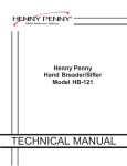
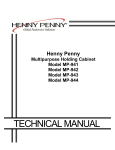
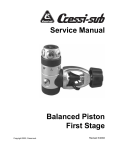
1
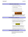
Henny Penny
Open Fryer-Electric
Model OFE-290
TECHNICAL MANUAL
Model 290
TABLE OF CONTENTS
Section
Page
Section 1.
TROUBLESHOOTING ............................................................................................. 1-1
1-1
Introduction .................................................................................................... 1-1
1-2
Safety ............................................................................................................. 1-1
1-3
Troubleshooting .............................................................................................. 1-2
1-4
Error Codes .................................................................................................... 1-9
Section 2.
MAINTENANCE ....................................................................................................... 2-1
2-1
Introduction .................................................................................................... 2-1
2-2
Maintenance Hints ......................................................................................... 2-1
2-3
Preventive Maintenance ................................................................................ 2-1
2-4
High Temperature Limit Control .................................................................... 2-2
2-5
Fuse Holders .................................................................................................. 2-4
2-6
Power/Pump Switch ...................................................................................... 2-5
2-7
Temperature Probe Replacement .................................................................. 2-6
2-8
Complete Control Panel - Henny Penny ........................................................ 2-7
2-9
Contactors ...................................................................................................... 2-8
2-10
Heating Elements ........................................................................................... 2-10
2-11
Drain Microswitch ......................................................................................... 2-13
2-12
Drain Valve and Extension ............................................................................. 2-14
2-13
Nylatron Strips Replacement ......................................................................... 2-15
2-14
Lid Couterweight Cables ................................................................................ 2-17
Wiring Diagrams ............................................................................................ 2-18
Section 3.
PARTS INFORMATION ........................................................................................... 3-1
3-1
Introduction .................................................................................................... 3-1
3-2
Genuine Parts ................................................................................................. 3-1
3-3
How To Order ................................................................................................ 3-1
3-4
Prices ............................................................................................................. 3-1
3-5
Delivery .......................................................................................................... 3-1
3-6
Warranty ........................................................................................................ 3-1
3-7
Recommended Spare Parts for Distributors .................................................. 3-1
3-8
Idex of Parts Lists Illustrations ...................................................................... 3-2
106
FM06-025
Revised 07-25-07
i
Model 290
SECTION 1. TROUBLESHOOTING
1-1. INTRODUCTION
This section provides troubleshooting information in the form
of an easy to read table.
If a problem occurs during the first operation of a new fryer,
recheck the installation per the Installation Section of this
manual.
Before troubleshooting, always recheck the operation procedures per Section 3 of this manual.
1-2. SAFETY
Where information is of particular importance or safety related,
the words DANGER, WARNING, CAUTION, and NOTICE are
used. Their usage is described below.
SAFETY ALERT SYMBOL is used with DANGER,
WARNING, or CAUTION which indicates a personal injury
type hazard.
NOTICE is used to highlight especially important information.
CAUTION used without the safety alert symbol indicates
a potentially hazardous situation which, if not avoided,
may result in property damage.
CAUTION indicates a potentially hazardous situation
which, if not avoided, may result in minor or moderate
injury.
WARNING indicates a potentially hazardous situation
which, if not avoided, could result in death or serious
injury.
DANGER INDICATES AN IMMINENTLY
HAZARDOUS SITUATION WHICH, IF NOT
AVOIDED, WILL RESULT IN DEATH OR SERIOUS
INJURY.
1-1
1103
Model 290
1-3. TROUBLESHOOTING
To isolate a malfunction, proceed as follows:
1.
Clearly define the problem (or symptom) and when it
occurs.
2.
Locate the problem in the Troubleshooting table.
3.
Review all possible causes. Then, one-at-a-time work
through the list of corrections until the problem is solved.
4.
Refer to the maintenance procedures in the Maintenance
Section to safely and properly make the checkout and repair needed.
If maintenance procedures are not followed correctly,
injuries and/or property damage could result.
1103
1-2
Model 290
Problem
Cause
Correction
COOKING SECTION
Product color not correct:
A. Too dark
• Temperature too high
• Check temperature setting
in the program mode; see
Programming Section in
Operator’s Manual
• Faulty temperature probe
• Remove and replace temperature probe
• Shortening too old
• Change shortening
• Shortening too dark
• Filter shortening
• Change shortening
• Breading product too far
• Bread product closer to
in advance
B. Too light
• Temperature too low
actual frying period
• Check temperature setting
• Remove and replace temperature probe
• Fryer incorrect preheat
• Allow proper preheat time
• Slow fryer heat-up/recovery
• Faulty element
• Wrong cook button
• Be sure to select the correct
pushed.
C. Product
greasy
amount of product to be cooked
• Shortening old
• Replace shortening
• Temperature too low
• Check temperature setting
• Temperature not recovered
when product was dropped
in frypot
• Faulty temperature probe
• Remove and replace defective
temperature probe
• Frypot overloaded
• Reduce cooking load
• Product not removed from
• Remove product from
frypot immediately after
end of cycle
1-3
frypot immediately after
end of cycle
1203
Model 290
Problem
Cause
Correction
COOKING SECTION (Continued)
D. Spotted
product
• Improper separation of the
product
• Breading not uniform on
the product
• Load product into racks
properly
• Sift breading regularly
• Separate product during
breading
• Burned breading particles
on product
• Product sticking together
• Filter the shortening more
frequently
• Separate product prior to
pressure cooking
E. Dryness of
product
• Moisture loss prior to
• Use fresh products
cooking
• Overcooking the product
• Reduce cooking time
• Reduce cooking
temperature
• Wrong cook button pushed
• Be sure to select the
correct amount of
product to be cooked
Product flavor
(taste):
A. Salty taste
• Breading mixture is too salty
• Sift breading after each use
• Incorrect breading mixture
• Discard old breading
• Incorrect choice of
• Use breading designed for
breading
B. Burned taste
C. Bland taste
• Burned shortening favor
• Replace shortening
• Frypot not properly cleaned
• Drain and clean frypot
• Raw product not fresh
• Use fresh raw product
• Breading mixture incorrect
• Use breading designed for
for product (spice content
too low)
• Cooking temperature too
high (spice flavors lost)
1103
the desired product
desired product
• Check temperature
1-4
Model 290
Problem
D. Rancid taste
Cause
COOKING SECTION (Continued)
• Shortening too old
Correction
• Replace shortening, and
follow recommended care
and use of shortening
• Infrequent filtering
• Replace shortening and
follow recommended care
and use of shortening
• Non-compatible products
cooked within the same
• Replace shortening
• Use compatible products,
shortening. - and follow
recommended care and use of
shortening
• Raw product not fresh
• Use fresh product
• Incorrect meat cut
• Use correct meat cutting
General:
A. Meat
separation
from bone
B. Bone color
not proper
procedures
• Overcooking
• Check cooking time
• Product not fresh
• Use fresh product
• Using frozen product
• Use fresh product
(black bone)
• Improper processing of
product (black bone)
• Product not thoroughly
cooked (red bone)
C. Breading falls
off
• Incorrect breading
procedures
• Product partially frozen
• Use proper processing
procedure for product
• Check cooking time
• Check cooking temperature
• Use correct breading
procedure
• Thoroughly thaw the
product, before breading
D. Product
sticking
together
• Product breaded too long
prior to cooking
• Improper loading
procedure
• Wrong cook button pushed
• Refer to breading and
frying instructions
• Properly load product per
loading procedures
• Be sure to select the
correct amount of product to
be cooked
1-5
103
Model 290
Problem
With switch in
POWER position,
the fryer is completely inoperative
(NO POWER)
Cause
POWER SECTION
• Open circuit
Correction
• Check to see that unit is
plugged in
• Check the breaker or fuse
at supply box
• Check voltage at wall
receptacle
• Check MAIN POWER
switch; replace if defective
• Check cord and plug
• Check 15 amp fuses
Shortening will not heat
HEATING OF SHORTENING SECTION
• Blown fuse or tripped
• Reset breaker or replace fuse
circuit breaker at supply
box or control panel
• Blown fuse in PC board
• Replace glass fuse in board
• Faulty POWER/PUMP switch.
• Check POWER/PUMP switch
per maintenance section on
the POWER/PUMP switch
• Faulty cord and plug
• Check cord and plug
• Check power at receptacle
• Faulty drain switch
• Check drain switch per
maintenance section on
drain switches
• Faulty PC Board
• Remove and replace control
panel
• Faulty high limit control switch
• Check high limit control
switch per maintenance
section on the high limit
• Drain valve open
• Close drain valve
• Possible faulty temperature probe
• Replace temperature probe
• Faulty contactor
• Check contactor per maintenance
section on contactors
1203
1-6
Model 290
Problem
Cause
Correction
HEATING OF SHORTENING SECTION (Continued)
Heating of shortening
• Low or improper voltage
• Use a meter and check the
receptacle against data plate
• Weak or burnt out element(s)
• Check heating element(s) per
Heating Elements Section
• Points in contactor bad
• Check contactor per Heating
Contactors Section
• Wire(s) loose
• Tighten
• Burnt or charred wire
connection
• Replace wire and clean
connectors
• Programming wrong
• Check temperature setting
in the program mode
• Faulty PC board
• Remove and replace control
panel
• Faulty temperature probe
• Remove and replace temperature
probe
• Check contactor for not
opening
• Check faulty contactor per
Heating Contactors Section
too slow
Shortening
overheating
1-7
1103
Model 290
Problem
Cause
Correction
SHORTENING FOAMING/DRAINING SECTION
Foaming or boiling
over of shortening
• Water in shortening
• At end of a Cook Cycle,
drain shortening and clean
frypot; add fresh shortening
• Condensation line stopped up
• Remove and clean condensation
line
• Improper or bad
shortening
• Use recommended
shortening
• Improper filtering
• Refer to the procedure
covering filtering the shortening
• Cold zone full of cracklings
• Filter shortening
• Improper rinsing after
cleaning the fryer
• Clean and neutralize the
frypot; rinse with vinegar
to remove the alkaline, then
rinse with hot water and
dry frypot
Shortening will
not drain from frypot
• Drain valve clogged with
crumbs
• Open valve - push cleaning
rod through drain opening from
inside of frypot
Shortening leaking
through drain valve
• Obstruction in drain
• Remove obstruction
• Faulty drain valve
• Replace drain valve
1103
1-8
Model 290
1-4. ERROR CODES
DISPLAY
In the event of a control system failure, the digital display shows an
error message. These messages are coded: “E04”, “E05”, “E06”,
“E41”. A constant tone is heard when an error code is displayed,
and to silence this tone, press any of the product buttons.
CAUSE
PANEL BOARD CORRECTION
“E04”
Control board overheating
Turn switch to OFF position, then turn
switch back to ON; if display still shows
“E04”, the board is getting too hot; check for
signs of overheating behind the control
panel; once panel cools down the controls
should return to normal; if “E04” persists,
replace the control
“E05”
Shortening overheating
Turn switch to OFF position, then back to
ON; if display shows “E05”, the heating
circuits and temperature probe should be
checked; once the unit cools down, the
controls should return to normal; if “E05”
persists, replace the controls
“E06”
Temperature probe failure
Turn switch to OFF position, then back to
ON; if the display shows “E06”, the temperature probe should be checked; once the
temperature probe is repaired, or replaced, the
controls should return to normal; if “E06”
persists, replace the controls
“E41”
Programming Failure
Turn switch to OFF position, then back to
ON. If display shows “E41”, the control
should be re-initialized (see programming
section); if the error code persists, replace
the control panel.
“E71”
Pump motor relay failure or
wiring problem
Replace relay if contacts are stuck closed;
check wiring on POWER/PUMP switch, or at
wall receptacle; L1 and N may be reversed
1-9
1103
Model 290
1-4. ERROR CODES (Continued)
CE Only - Along with the error codes from page 1-11, CE
units have the following self-diagnostic error codes:
DISPLAY
CAUSE
“E10”
High limit
Reset the high limit by manually pushing up on the red reset
button; if the high limit does not reset, the high limit must be
replaced per the High Limt Temperature Control Section
“E15”
Drain Switch
Close the drain, using the drain valve handle; if display still
shows “E-15”, check the drain microswitch per the Drain
Switch Section
1103
PANEL BOARD CORRECTION
1-12
Model 290
SECTION 2. MAINTENANCE
2-1. INTRODUCTION
This section provides checkout and replacement procedures, for
various parts of the fryer. Before replacing any parts, refer to the
Troubleshooting Section to aid you in finding the cause of the
malfunction.
2-2. MAINTENANCE HINTS
1. A multimeter will help you to check the electric components.
2. When the manual refers to the circuit being closed, the
multimeter should read zero unless otherwise noted.
3. When the manual refers to the circuit being open, the multimeter
should read infinity.
Do not move the fryer with hot shortening in the frypot or
filter pan. Severe burns can result from splashing hot
shortening.
4. Remove weights from the frame to easily access rear of fryer.
2-3. PREVENTIVE
MAINTENANCE
2-1
To ensure a long life of the fryers and their components, regular
maintenance should be performed. Refer to the chart below.
Frequency
Action
Twice Daily
Filter Shortening (See Filtering
Instructions Section in Operator’s
Manual)
Annually
Lubricate Lid Rollers in back of fryer.
(See Lubricating Lid Rollers Section)
Annually
Inspect lift cables
712
Model 290
2-4. HIGH TEMPERATURE
LIMIT CONTROL
This high temperature control is a safety, manual reset control,
which senses the temperature of the shortening. If the shortening
temperature exceeds 425°F (218°C), this switch opens and shuts
off the heat to the frypot. When the temperature of the shortening
drops to a safe operation limit, manually reset by pressing the red
reset button. The red reset button is located under the control
panel, in the front of the fryer, to the right of the drain. Once reset,
the frypot starts heating.
Checkout
Before replacing a high temperature limit control, check to see
that its circuit is closed.
The shortening temperature must be below 380°F (193°C) to
accurately perform this check.
1. Remove electrical power supplied to the fryer.
To avoid electrical shock or property damage, move the
power switch to OFF and disconnect main circuit
breaker, or unplug cord at wall receptacle.
2. Remove the control panel.
3. Remove the inner heat shield.
4. Remove the two nuts securing the high limit bracket to the unit,
and pull the bracket from the unit.
5. Remove the two screws securing the high limit to the bracket,
and remove the high limit from the bracket.
6. Remove the two electrical wires from the high temperature
limit control.
7. Manually reset the control, then check for continuity between
the two terminals after resetting the control. If the circuit is
open, replace the control, then continue with this procedure. (If
the circuit is closed, the high limit is not defective. Reconnect
the two electrical wires.)
1103
2-2
Model 290
2-4. HIGH TEMPERATURE
LIMIT CONTROL
(Continued)
To avoid electrical shock of property damage, move the
power switch to OFF and disconnect main circuit
breaker, or unplug cord at wall receptacle.
Replacement
1. If the tube is broken or cracked, the control will open,
shutting off electrical power. The control cannot be reset.
2. Drain shortening from the frypot and discard. A substance
in the tube could contaminate the shortening.
3. Remove control panel.
4. Loosen small inside screw nut on capillary tube.
5. Remove capillary bulb from bulb holder inside the frypot.
6. Straighten the capillary tube.
7. Remove larger outside nut that threads into pot wall, and
remove defective control from control panel area.
8. Insert new control and replace screws.
9. Uncoil capillary line, starting at capillary tube, and insert
through frypot wall.
To avoid electrical shock or other injury, run the capillary
line under and away from all electrical power wires and
terminals. The tube must never be in such a position
where it could accidentally touch the electrical power
terminals.
10. Carefully bend the capillary tube as shown in photo and place
into bulb brackets.
2-3
1103
Model 290
2-4. HIGH TEMPERATURE
LIMIT CONTROL
(Continued)
11. Pull excess capillary line from pot and tighten nut into frypot wall.
Be sure capillary bulb of high limit is positioned so it doesn’t
interfere with the carrier or get damaged when cleaning the
frypot.
12. With excess capillary line pulled out, tighten smaller nut.
13. Replace inner and front panels.
14. Refill with shortening.
2-5. FUSE HOLDERS
There are two fuse holders on each model of the electric fryers. To
check or change fuse, unscrew black fuse holder cap.
To avoid electrical shock or property damage, move the
power switch to OFF and disconnect main circuit
breaker, or unplug cord at wall receptacle.
Checking Procedure for Fuse Holders
CONTROL PANEL FUSES 3 Phase
Remove the control panel and pull the wires from the fuse holder
terminals. Using a multimeter or continuity light, check across the
terminals. The circuit should be closed. If not, replace the fuse
(HP# EF02-007) or fuse holder (HP# EF02-006).
1103
2-4
Model 290
2-6. POWER/PUMP SWITCH
The POWER/PUMP switch is a three way rocker switch with a
center OFF position. With the switch in the POWER position the
fryer operates. With the switch in the PUMP position the filter pump
operates, but the unit will not heat.
To avoid electrical shock or property damage, move the
power switch to OFF and disconnect main circuit
breaker, or unplug cord at wall receptacle.
Checkout
1. Remove control panel.
2. Label and remove wires from the switch.
3. OFF position-should be open circuit anywhere on the switch.
4. Power position. Check from: #5 to #6 closed circuit
#l to #2 closed circuit
5. Pump position. Check from:
#4 to #5 closed circuit
#3 to #2 closed circuit
Check across the jumpers on the wires of the POWER/PUMP
switch. These jumpers have resistors and capacitors which
may be faulty.
Replacement
1. With control panel removed, and wires off of the switch,
push in on tabs on the switch to remove from the panel.
2. Replace with new switch, and reconnect wires to switch
following the wiring diagram.
3. Replace the control panel.
2-5
1103
Model 290
2-7. TEMPERATURE PROBE
REPLACEMENT
The temperature probe relays the actual shortening temperature to
the control. If it becomes disabled, “E06” will show in the display.
Also, if the temperature is out of calibration more than 10°F, or
10°C, the temperature probe should be replaced. An Ohm check
can be performed also. See chart at end of this section.
1. Remove electrical power supplied to the fryer.
To avoid electrical shock or property damage, move the
power switch to OFF and disconnect main circuit
breaker, or unplug cord at wall receptacle.
2. Drain the shortening from the frypot.
3. Remove the control panel.
4. Using a 1/2" wrench, remove the nut on the compression fitting.
Figure 2-1
5. Remove the temperature probe from the frypot.
6. Place the nut and new ferrule on the new temperature probe and
insert the temperature probe into the compression fitting until it
extends one-half (1/2) inch (1.3 cm) into the frypot. Use the
temperature probe gauge provided in the temperature probe kit,
to ensure proper placement in frypot. See Figures 2-1 and 2-2.
7. Tighten hand tight and then a half turn with wrench.
Figure 2-2
Excess force will damage temperature probe.
8. Connect new temperature probe to PC board and replace
control panel.
9. Replace shortening.
10. Turn power on and check out fryer.
307
2-6
Model 290
2-8. COMPLETE CONTROL
PANEL-HENNY PENNY
Should the control panel become inoperative, follow these instructions for replacing the board.
1. Remove electrical power supplied to the fryer.
To avoid electrical shock or property damage, move the
power switch to OFF and disconnect main circuit
breaker, or unplug cord at wall receptacle.
2. Remove the two screws securing he control panel and lift
panel up and out
3. Unplug the connectors going to the control board.
4. Install a new control panel.
2-7
1103
Model 290
2-9. CONTACTORS
The electric fryer requires two switching contactors: a primary and a
heat contactor. The primary contactor energizes (contacts close)
any time the POWER/PUMP switch is in the POWER position, and
the temperature of the shortening is below 420° F ( 215° C). The
high limit cuts power at the primary contactor if the temperature of
the shortening is above 420° F ( 215° C). The primary contactor
supplies power to one side of the heat contactor.
Primary
The heat contactor is controlled by the computer controller. When
the controller calls for heat, the heat contactor applies power to one
side of the heating elements. When the heat contactor and primary
contactor are energized (contacts closed) the electric heating
elements heat the shortening.
The photo shows a mercury heat contactor, but CE countries
will have an electromechanical heat contactor.
Heat
30
31
32
Checkout
1. Remove electrical power supplied to the fryer.
33
To avoid electrical shock or property damage, move the
power switch to OFF and disconnect main circuit
breaker, or unplug cord at wall receptacle.
37
2. Remove the control panel.
34
1103
35
36
3. Label and remove wires from contactors and perform a check
on both contactors as follows:
Test Points
Results
From 23 to 29
open circuit
From 24 to 28
open circuit
From 25 to 27
open circuit
From 30 to 34
open circuit
From 31 to 35
open circuit
From 32 to 36
open circuit
From 33 to 37
ohm reading 1700
From 22 to 26
ohm reading 415
2-8
Model 290
2-9. CONTACTORS
(Continued)
To avoid electrical shock, make connections before
applying power, take reading, and remove power
before removing meter leads. The following checks
are performed with the wall circuit breaker closed and
the main power switch in the ON position.
4. With power reapplied and in a heat-up mode, check the
power going to both contactor coils. This is to be sure power is
going to the contactors.
If no voltage is found going into the primary contactor coil, check
wiring, high limit, and drain switch. If no voltage at heat contactor
coil check wiring and connections at PC board.
Replacement
If either contactor proves defective, replace as follows:
To avoid electrical shock or property damage, move the
power switch to OFF and disconnect main circuit
breaker, or unplug cord at wall receptacle.
1. Label and remove only those wires directly connected to the
contactor being replaced.
Hint: Removing the left side panel may be helpful in replacing
the heat contactor.
2. Remove the mounting screws on the base plate of the primary
contactor and remove contactor. Proceed to step 5.
3. Remove the screws securing the mercury contactor bracket to
the mounting plate and remove bracket and contactor.
4. Remove the screws securing the contactor to the bracket and
remove contactor from bracket.
5. Install new contactor in reverse order.
6. Install control panel and reconnect power to the fryer and test
for proper operation.
2-9
1103
Model 290
2-10. HEATING ELEMENTS
The electric model fryer uses 2 heating elements.
Heating elements are available in 208, 220/240, 380 and 415
volts. Check the data plate, on the shroud behind the lid, to
determine the correct voltage elements.
1. Remove the electrical power supplied to the unit.
To avoid electrical shock or property damage, move the
power switch to OFF and disconnect main circuit
breaker, or unplug cord at wall receptacle.
2. Remove the control panel.
3. Remove both side panels.
4. Remove upper screws and loosen the lower screws, to the front
control shroud, and hinge it down. (See photo at left)
To avoid electrical shock, make connections before
applying power, take reading, and remove power before
removing meter leads. The following checks are per
formed with the wall circuit breaker closed and the main
power switch in the ON position.
5. Perform an amp check on one heating element at a time with the
wires connected to the contactors. The 2 heaters actually have
3 small heating elements on the inside of the outer plate. It is
important to check between the correct wires to obtain the
accurate amp reading. The wires are labeled for your
convenience.
Wires
L1-L3
L3-L2
L2-L1
L1-L2
L3-L2
L2-L1
1103
Power
8500W
8500W
8500W
8500W
8500W
8500W
Voltage
208V
208V
208V
240V
240V
240V
Amperage
47.8
47.9
48.0
39.4
40.1
39.9
2-10
Model 290
2-10. HEATING ELEMENTS
(Continued)
Replacement
1. Drain the shortening.
2. Remove the high limit bulb holder from the heating
element inside the frypot.
3. Disconnect the heating element wires from the contactors.
Label each so it can be replaced in the same position on the
new element.
4. Remove the heat contactor, as described in Contactors Section,
to access the left side element nuts.
5. Loosen the screws on the element spreaders.
6. Slide the element spreaders to the center of the heating element.
7. Using a 7/8” crowsfoot, remove the brass nuts and washers
which secure the ends of the elements through the frypot wall.
8. Remove the heating elements from the frypot as a group by
lifting the far end, and sliding them up and out towards the rear
of the frypot.
Always install new rubber O rings (2) when installing heating
elements.
9. Install new heating elements with new rubber O-rings
mounted on terminal ends, and spreaders loosely
mounted in the center of the stacked elements.
10. Replace the heating elements, terminal end first at
approximately 45º angle, slipping the terminal ends through the
front wall of the frypot.
2-11
1103
Model 290
2-10. HEATING ELEMENTS
(Continued)
10. Replace the brass nuts and washers on the heating element
terminals. Tighten the brass nuts to 30 foot lbs of torque.
11. Replace heat contactor.
11. Move the element spreaders from the center of the element,
into a position which will spread each element apart evenly on
all four sides, and tighten.
12. Replace the high limit bulb holder on the top element, and
position the bulb between the top and second element midway
from side to side, and tighten screw which holds the bulb in
place.
13. Reconnect the wires to the appropriate terminal as labeled
when they were removed.
14. Replace the front control shroud and control panel.
15. Replace side panels.
16. Connect the power cord to the wall receptacle or close
wall circuit breaker.
Heating elements should never be energized without
shortening in the frypot, or damage to elements could
result.
1103
2-12
Model 290
2-11. DRAIN MICROSWITCH
Upon pulling out on the drain handle, the microswitch should
be activated and the unit will not heat, but when the handle is
pushed back, the unit should operate properly. The bracket on the
microswitch is slotted so it can be adjusted backward or forward.
1. Remove electrical power supplied to the unit.
To avoid electrical shock or property damage, move the
power switch to OFF and disconnect main circuit
breaker, or unplug cord at wall receptacle.
2. The following check should be made to determine if the
drain switch is defective.
a. Remove bracket from the unit.
b. Remove wires from the switch.
c. Check for continuity across the two outside terminals
on the drain switch. If circuit is open, the drain switch
is bad. The circuit should only be opened by pressing
on the actuator of the drain switch.
1/8” (4 mm) Gap
3. To replace switch, remove switch from the bracket, and install
switch in reverse order.
4. Test to see if drain valve handle actuates the switch. The gap
between the drain switch and the shaft should be no more than
1/8” (3 mm).
HINT: Listen for click of switch while pulling drain
valve handle.
2-13
1103
Model 290
2-12. DRAIN VALVE
AND EXTENSION
The drain valve opens when the drain valve handle is pulled out
and drains the shortening out of the pot.
Replacement
1. Using a 3/8” socket, remove the nuts securing the drain switch
bracket, and pull the bracket from the studs.
2. Remove the nut securing the drain handle and pull the handle
from the drain valve.
3. Using a large adjustable wrench, unscrew the drain valve and
extension from the unit.
4. Replace the drain valve and extension.
5. Replace the drain switch bracket.
6. Adjust the microswitch to be no more than 1/8” (3 mm) from
the shaft of the drain valve.
HINT: Listen for click of switch while pulling drain valve handle.
1103
2-14
Model 290
2-13. NYLATRON STRIPS
REPLACEMENT
1. Raise the lid and remove the retention ring from one end of the
lid pin.
2. Slide the lid pin from unit.
3. Lift the lid from unit.
4. Using a 3/8” socket, remove the nuts securing the rear shroud
and remove shroud.
5. Using a Phillip’s-head screwdriver, remove the screws securing
the top cap and remove top cap.
6. Remove the bolts securing the nylatron strips to the weight
assembly and remove strips from weight assembly.
7. Using a Phillip’s-head screwdriver, remove the screws securing
the front shroud.
2-15
104
Model 290
2-13. NYLATRON STRIPS
REPLACEMENT (Continued)
8. Lift the front shroud up and out, over the arm of the lid.
9. Thread the new nylatron strip through the track in the front
shroud.
10. Lining up the holes in the strips, fit the front shroud back over
the lid arms.
11. Secure the strips to the weight assembly.
12. Replace back shroud, top cap, and lid, and replacement is
complete.
104
2-16
Model 290
2-14. LID COUNTERWEIGHT
CABLES
The Lid Counterweight in the back of the fryer balances the weight
of the lid system to allow easier opening and closing of the lid. The
weight has two cables attached to it, and weighs about 100 lbs.
(45.4 kg).
1. Using a 3/8” socket, remove the nuts securing the rear shroud
of the fryer and remove the shroud.
2. Using Phillip’s-head screwdriver, remove the screws securing
the top cap and remove cap.
3. Raise the lid.
4. Unscrew the broken cable from the weight assembly and the
bracket attached to the fryer, and remove broken cable.
5. Screw a 5/16” nut on each end of the new cable.
6. Using a wrench, screw the new cable into the weight assembly
until tight.
7. Using a 1/2” wrench, tighten the nut (already threaded on the
cable) against the weight assembly, securing the cable into the
weight assembly.
8. Pull the cable over the pulley and down behind the weight
assembly.
9. Insert the cable into the hole in the bracket and screw a 5/16”
nut onto the end of the cable. Tighten the cable, by screwing
the cable through this nut until the weight assembly becomes
level.
The safety cable should now have slack in it with the weight
assembly level.
10. Tighten the nut against the top of the bracket, securing the
cable.
11. Replace the top cap and rear shroud and repair is now complete.
2-17
104
Model 290
SN: BE0608002 & Below
307
2-18
Model 290
SN: BE0608002 & Below
2-19
307
Model 290
SN: BE0608003 & Above
707
2-20
Model 290
SN: BE0608002 & Below
2-21
307
Model 290
SN: BE0608003 & Above
707
2-22
Model 290
SN: BE0608002 & Below
2-23
307
Model 290
SN: BE0608003 & Above
707
2-24
Model 290
2-25
707
Model 290
707
2-26
Model 290
2-27
307
Model 290
SECTION 3. PARTS INFORMATION
3-1. INTRODUCTION
This section lists the replaceable parts of the Henny Penny Model
290 fryer.
3-2. GENUINE PARTS
Use only genuine Henny Penny parts in your fryer. Using a part of
lesser quality or substitute design may result in damage to the unit or
personal injury.
3-3. WHEN ORDERING PARTS
Once the parts that you want to order have been found in the parts
list, write down the following information:
Item Number
2
Part Number 16738
Description High Limit
Example:
From the data plate, list the following information:
Product Number 01100
Serial Number
0001
Voltage
208
Example:
3-4. PRICES
Your distributor has a price parts list and will be glad to inform you
of the cost of your parts order.
3-5. DELIVERY
Commonly replaced items are stocked by your distributor and will
be sent out when your order is received. Other parts will be
ordered, by your distributor, from Henny Penny Corporation.
Normally, these will be sent to your distributor within three working
days.
3-6. WARRANTY
All replacement parts (except lamps and fuses) are warranted for
90 days against manufacturing defects and workmanship. If damage occurs during shipping, notify the carrier at once so that a claim
may be properly filed. Refer to warranty in the front of this manual
for other rights and limitations.
3-7. RECOMMENDED
SPARE PARTS FOR
DISTRIBUTORS
Recommended replacement parts, stocked by your distributor, are
indicated with √ in the parts lists. Please use care when ordering
recommended parts, because all voltages and variations are
marked. Distributors should order parts based upon common
voltages and equipment sold in their territory.
106
3-1
Model 290
3-8. INDEX OF PARTS LIST ILLUSTRATIONS
Title
Fig. No.
FRAME AND COVER ASSEMBLY .............................................................
3-1
3-3
ELEMENT ASSEMBLY ................................................................................
3-2
3-5
COUNTERWEIGHT SYSTEM .....................................................................
3-3
3-6
LID ASSEMBLY ...........................................................................................
3-4
3-7
CONTROL PANEL ASSEMBLY ..................................................................
3-5
3-8
BEHIND CONTROL PANEL COMPONENTS ...........................................
3-6
3-9
FILTER PUMP ASSEMBLY (SN: LG012JC & BELOW) .............................
3-7A
3-10
FILTER PUMP ASSEMBLY (SN: LG013JC & ABOVE) ..............................
3-7B
3-12
DRAIN VALVE & DRAIN SWITCH ASSEMBLIES ...................................
3-8
3-14
DRAIN PAN AND FILTER ASSEMBLY ......................................................
3-9
3-15
CARRIER, RACKS & JUNCTION BOX ASSY ..........................................
3-10
3-17
3-2
Page No.
104
Model 290
Figure 3-1. Frame and Cover Assembly
205
3-3
Model 290
Figure &
Item No.
3-1
1
2
√ 3
4
5
6
7
8
9
10
11
12
12
13
14
Part No.
Description
39796
53669
29898
54225
53673
37246
SC03-005
66934
SC01-215
37291
35726
66933
14457
36337
SC02-023
FRAME & COVER ASSEMBLY
WELDMENT – CONTROL PANEL FRONT ..........
GUARD – POWER SWITCH ...................................
SWITCH – POWER .................................................
1" INSERT – LEG MACHINED ...............................
CASTER, SWIVEL 4" ...............................................
CASTER W/BRAKE & SWIVEL LOCK .................
SCREW - - #8 x 1/2” PH PHD ..................................
SIDE PANEL – RIGHT .............................................
SCREW - 5/16-18 x 2.5” HEX HD BOLT ................
REAR SHROUD – ACCESS ASSEMBLY ................
TOP COVER – REAR SHROUD ..............................
SIDE PANEL – LEFT ................................................
KIT - SOUND DEADENING ...................................
DOOR – ACCESS ....................................................
SCREW - #8-B x 3/8” PH THD SS ...........................
Qty.
1
1
1
4
2
2
4
1
4
1
1
1
1
1
5
√ recommended parts
3-4
106
Model 290
Figure &
Item No.
3-2
1
2
3
4
5
6
√ 7
√ 7
√ 7
√ 7
8
9
10
Part No.
Description
SC01-083
35101
35100
SC01-074
35435
35462
35234
35598
48367
36290
16855
WA01-005
NS01-017
ELEMENT ASSEMBLY
SCREW, (#10-32 x 1/2 PH FHD) ..............................
SUPPORT, ELEMENT - LONG ................................
SUPPORT, ELEMENT - SHORT ..............................
SCREW, (#10-32 x 1/2 PH THD S) ...........................
BRACKET, HI LIMIT PROBE ..................................
BRACKET, HI LIMIT PROBE ..................................
HEAT ELEMENT ASSEMBLY, 8.5 KW 208V ..........
HEAT ELEMENT, 8.5 KW 240V ..............................
HEAT ELEMENT, 230 V(Int’l Only) ..........................
HEAT ELEMENT, 220 V(Int’l Only) ..........................
SEAL, O-RING .........................................................
WASHER, (5/8 DIA. TYPE A - SERIES N) ...............
NUT, (5/8-18 B HEX) ................................................
Qty.
As Required
5
5
As Required
3
3
2
2
2
2
4
8
4
√ recommended parts
106
3-5
Model 290
Figure &
Item No.
3-3
1
√ 2
3
4
5
6
7
8
9
10
11
12
13
14
15
Part No.
Description
35026
140225
NS01-025
LW01-010
35092
SC01-069
36839
SC01-042
36625
36627
36626
37362
37363
37364
SC01-081
COUNTERWEIGHT SYSTEM
ARM, LID SUPPORT .....................................................
KIT-CABLE (2 CABLES) ...............................................
NUT, HEX 5/16-18 SS .....................................................
WASHER, 3/8 SPLIT RING SS ......................................
CARRIAGE ......................................................................
SCREW, 3/8-16 X 1-1/2 HEX HD S2P ...........................
SLIDE ...............................................................................
SCREW, 3/8-16 X 1 HEX C .............................................
WELD ASSEMBLY, C/W CARRIAGE ..........................
COUNTERWEIGHT BAR ..............................................
SPACER, C/W FRAME ..................................................
WHEEL, CARRIAGE .....................................................
SPACER, CARRIAGE WHEEL .....................................
SPINDLE ..........................................................................
SCREW, 3/8-24 X 3/4 HEX HD SS .................................
Qty.
2
1
10
10
1
8
2
2
1
4
2
4
4
4
4
√ recommended parts
3-6
712
Model 290
Figure &
Item No.
Part No.
3-4
1
2
3
4
5
6
7
7a
7b
8
65818
RR01-004
WA01-020
51531
SC01-041
55754
55756
59169
52498
51707
SC01-248
512
Description
Lid Assembly Complete
Ring - Retaining - 1/2 in.
Washer - .513 ID-.750 OD-.05 THK
Stop - Lid, Cast
Screw - 5/16”-18 x 1 HEX HD C
Handle Weld Assembly
Assy. - Latch/Sleeve Coat
Lid Latch Bracket
Spring - Lid Latch
Lid Latch Bracket
Screw 10-32 x 1.25 PH THD SS
Qty.
1
1
1
2
1
1
1
1
1
2
3-7
Model 290
Figure &
Item No.
3-5
√ 1
√ 1
√ 1
2
3
4
√ 5
6
7
8
9*
Part No.
Description
55848RB
93553
72160RB
50624
61748
NS02-005
51877
SC01-049
NS02-005
72500
14620
CONTROL PANEL ASSEMBLY
CONTROL ASSY – KFC 290 SMS ......................
ASSY-CONTROL-KFC ZIGB 290-DOM ............
CONTROL ASSY – 290 SMS-W/O SETPOINTS
CONTROL DECAL – 8 HEAD KFC ..............
MENU CARD ..................................................
NUT .................................................................
WIRE/SPEAKER ASSY ..................................
SCREW ...........................................................
NUT .................................................................
ASSY – CONTROL COVER STUD ..............
KIT - CONTROL RETRO - 292 TO 290 ..............
√ recommended parts
3-8
Qty.
1
1
1
1
1
4
1
4
4
1
1
613
Model 290
7
1
6
5
4
2
Figure &
Item No.
Part No.
√
√
√
√
√
3-6
1
1*
1*
2
3
4
√ 5
√ 5
√ 6
29942
65075
65074
30971
19405
17216
16738
60241
EF02-125
√ 6
18364
√
√
√
√
√
EF02-006
EF02-007
EF02-104
EF02-105
14335
6
6
6
6
7
3
Description
Qty.
BEHIND CONTROL PANEL COMPONENTS
CONTACTOR - MERCURY 208/240 VAC ..............
1
ASSY.-240V E/M HEAT CONTACTOR-CE-240V (UK)
1
ASSY.-240V E/M HEAT CONTACTOR-CE-230V ..
CAPACITOR-RESISTOR ASSY ..............................
CONTACTOR KIT - 208/240 VAC ..........................
BRACKET ASSY- HIGH LIMIT ..............................
450° F HIGH LIMIT ..................................................
425° F HIGH LIMIT - CE ..........................................
BREAKER-PUSH BUTTON RESET-15 AMP ..........
SN: BE0608003 & ABOVE
FUSE HOLDER ASSY - 15 AMP ..............................
SN: BE0608002 & BELOW
FUSE HOLDER ..................................................
FUSE - 15 AMP ..................................................
FUSE HOLDER - 20A-250V ....................................
FUSE - 15 AMP - CE ................................................
PROBE KIT ...............................................................
1
1
1
1
1
1
2
2
2
2
1
1
1
√ recommended parts/* not shown
307
3-9
Model 290
Pump
Interior
3-7A. FILTER PUMP ASSEMBLY (SN: LG012JC & BELOW)
3-10
205
Model 290
Figure &
Item No.
Part No.
3-7A
1
2
√ 3
4
5
6
7
8
9
10
√ 11
12
√ 13
14
15
16
17
18
19
√ 20
√ 21
√ 22
√ 23
√ 24
√ 25
√ 26
√ 27
√ 28
29*
18107
54484
17476
18105
18644
51831
55836
16808
16809
17407
67583
62206
17430(use 69289)
16807
FP01-122
FP02-024
35472
FP02-007
17437
17454
17456
17451
SC01-016
SC01-026
SC01-132
17447
17446
17453
67589
Description
FILTER PUMP ASSEMBLY
CONDUIT CONNECTOR 3/8 X 90 ..............................
BLOWER/PUMP – FLEXIBLE CONDUIT ....................
PUMP SEAL KIT ............................................................
ANTI SHORT 3/8 INCH .................................................
CONDUIT CONNECTOR 3/8 X 90 ..............................
PUMP CONDUIT BRACKET ........................................
ASSY – OIL RETURN LINE ..........................................
SLEEVE, FITTING ...................................................
NUT, FITTING .........................................................
CONNECTOR, 1/2 MALE ELBOW ..............................
MOTOR – FILTER PUMP ..............................................
ASSY - TUBE - PUMP TO DISCON - 590 ...................
UNION, MALE FITTING ..............................................
FITTING, CONNECTOR MALE ...................................
REDUCER, 3/8 TO 1/2 ...................................................
NIPPLE, CLOSE 3/8 ......................................................
CHECK VALVE - PRESSURE .......................................
NIPPLE 3/8 X 1-1/2 ........................................................
PUMP SUBASSY 8GPM ................................................
BODY - PUMP .........................................................
PUMP SHIELD .........................................................
COVER - PUMP .......................................................
PLUG 1/4 HEX COUNTERSUNK ...........................
SCREW 5/16-18 X 3/4 HEX HD C ..........................
1/4-20 X 5/8 SOC HD CAP SCREW .......................
ROTOR - PUMP .......................................................
ROLLER - TEFLON SET .........................................
PUMP O RING GASKET .........................................
ASSY - FILTER PMP & 1/2 HP MOTOR .......................
Qty.
1
1
1
2
1
1
1
2
2
2
1
1
1
1
1
1
1
1
1
1
2
1
1
2
4
1
1
1
1
√ recommended parts
707
3-11
Model 290
Pump
Interior
3-7B. FILTER PUMP ASSEMBLY (SN: LG013JC & ABOVE)
3-12
205
Model 290
Figure &
Item No.
3-7B
1
2
√ 3
4
5
6
7
8
9
10
√ 11
12
13
14
√ 15
16
17
18
√ 19
√ 20
√ 21
√ 22
√ 23
√ 24
√ 25
√ 26
√ 27
Part No.
18107
54484
17476
18105
18644
51831
66618
16808
16809
FP01-169
67583
FP01-089
17407
62206
17430(use 69289)
21800
FP02-021
64218
SC01-132
23469
23468
23647
17456
23470
FP01-020
SC01-026
17453
Description
FILTER PUMP ASSEMBLY
CONDUIT CONNECTOR 3/8 X 90 ...........................
BLOWER/PUMP – FLEXIBLE CONDUIT .................
PUMP SEAL KIT .........................................................
ANTI SHORT 3/8 INCH ..............................................
CONDUIT CONNECTOR 3/8 X 90 ...........................
PUMP CONDUIT BRACKET .....................................
ASSY – OIL RETURN LINE .......................................
SLEEVE, FITTING ................................................
NUT, FITTING ......................................................
CON-90 MALE 3/4 TUBE 3/4 NPT ............................
MOTOR – FILTER PUMP ...........................................
BUSHING - REDUCING 3/4M TO 1/2F ....................
CONNECTOR, 1/2 MALE ELBOW ...........................
ASSY - TUBE - PUMP TO DISCON ..........................
UNION, MALE FITTING ...........................................
VALVE - 3/4 CHECK ..................................................
NIPPLE - 3/4 NPT X 3 IN LG BL ...............................
PUMP SUBASSY 8GPM .............................................
1/4-20 X 5/8 SOC HD CAP SCREW ....................
ROLLER - 7 GPM PUMP ......................................
ROTOR - 7GPM PUMP ........................................
BODY - 7 GPM PUMP ..........................................
PUMP SHIELD ......................................................
CAP - 7 GPM PUMP .............................................
PLUG 1/4-18 HEX LEVEL SEAL ..........................
SCREW 5/16-18 X 3/4 HEX HD C .......................
PUMP O RING GASKET ......................................
Qty.
1
1
1
2
1
1
1
2
2
2
1
1
1
√1
1
1
1
1
4
5
1
1
2
1
1
2
1
√ recommended parts
106
3-13
Model 290
Figure &
Item No.
Part No.
3-8
1
1
2
3
√ 4
5
6
7
7
8
9
10*
65520
66553
SC01-058
WA01-006
54228
NS02-005
52519
65522
67220
EF02-017
67617
76579
Description
DRAIN VALVE & DRAIN SWITCH ASSEMBLIES
DRAIN VALVE ASSEMBLY (SN: LG012JC & BELOW)
DRAIN VALVE ASSEMBLY (SN: LG013JC & ABOVE) .
SCREW #6-32 X 1 PH. PAN HD. ..................................
WASHER #6 TYPE A .....................................................
DRAIN SWITCH W/BOOT ...........................................
NUT #6-32 HEX .............................................................
CORD ASSY., DRAIN INTERLOCK ............................
BRACKET, SWITCH (BEFORE DEC. 29, 2003) ..........
BRACKET, SWITCH (AFTER DEC. 29, 2003) .............
STRAIN RELIEF ............................................................
BRACKET - MICROSWITCH TRIGGERING ..............
PLATE - D/I SWITCH COVER ......................................
Qty.
1
1
2
2
1
2
1
1
1
2
1
1
√ recommended parts
3-14
707
Model 290
3-9. DRAIN PAN AND FILTER ASSEMBLY
205
3-15
Model 290
Figure &
Item No.
Part No.
Description
3-9
1
2
2
2
3
4
5
6
7
52194
03203
21471
24429
52496
52487
SC01-009
NS02-002
17505
DRAIN PAN AND FILTER ASSEMBLY
CRUMB CATCHER (OPTIONAL) ............................
CRUMB CATCHER BASKET W/HANDLE (OPTIONAL)
“COLD ZONE” CRUMB CATCHER BASKET ASSY
HANDLE - CRUMB BASKET ...................................
FILTER DRAIN PAN ASSEMBLY ............................
CASTER .......................................................................
SCREW 1/4-20 X 1/2 ....................................................
NUT 1/4-20 ...................................................................
FILTER CLIPS .............................................................
8
8
9
10
11
11
√ 12
√ 13
√
√
√
14
15
16
17
18
19
19
20
21
22
23
24
25
26
17503(use 14674)
65447
17502(use 14674)
36305
24212
14658
17431(use 69289)
17432(use 69289)
24211
23740
SC01-245
23804
OR01-007
23803
66535
62082
12102
65776
35771
35310
12126
65211
Qty.
1
1
1
1
1
2
8
8
2
BOTTOM FILTER SCREEN (SN:BE0503009 AND BELOW) ..
BOTTOM FILTER SCREEN (SN: BE0503010 AND ABOVE) ..
TOP FILTER SCREEN (SN:BE0503009 AND BELOW) ...........
WASHER & STANDPIPE ......................................................
STANDPIPE ASSEMBLY (SN:BE0503009 AND BELOW) ......
KIT, 8 HEAD PICK-UP TUBE (SN BE0503010 & ABOVE)
1
1
1
1
1
UNION - MALE FITTING ..........................................
UNION - HANDLE FITTING ....................................
WELDMENT, FILTER TUBE AND WASHER .........
HANDLE, STANDPIPE 8 HEAD ..............................
SCREW 10-32 X 1/2 .....................................................
INSERT, FILTER NUT ................................................
O-RING, FILTER NUT INSERT .................................
FILTER NUT (SN:BE0503009 AND BELOW) ..........
FILTER NUT (SN BE0503010 & ABOVE) ................
FILTER DRAIN PAN COVER ASSEMBLY .............
FILTER ENVELOPE PAPER (100 PER CARTON) .
ROD - LONG CLEAN OUT .......................................
BRUSH .........................................................................
STIRRER ......................................................................
BLACK L-BRUSH ......................................................
CRUMB CATCHER ....................................................
1
1
1
1
3
1
1
1
1
1
1
1
1
1
1
1
√ recommended parts
3-16
307
Model 290
Figure &
Item No.
3-10
1
2
3
4
4
5
√ 6
7
8
8
9*
Part No.
67591
44782
35308
62126
62127
62106
51057
SC01-023
65180
65181
58146*
37560*
21519
Description
CARRIER, RACKS & JUNCTION BOX ASSY
CARRIER ASSY .............................................................
RACK HALF SIZE – 8 HEAD FRYER ...........................
WELDMENT - RACK HANDLE ...................................
JUNCTION BOX ASSY .................................................
JUNCTION BOX ASSY - CE ........................................
JUNCTION BOX - MACHINED ...................................
ASSY - EMC FILTER - CE ............................................
SCREW #6-32 X 1/4 PH RHD C ....................................
ASSY - MAIN POWER CORD ......................................
CORD - 291/591 POWER ........................................
PLUG-90, 60A, 3PH, 250V, #15-60P .......................
RECEPTACLE #15-60R .................................................
COVER - WIRE RACK (OPTIONAL) ..........................
Qty.
1
5
1
1
1
1
1
8
1
1
1
1
4
√ recommended parts/*not shown
1209
3-17