1
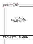
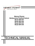
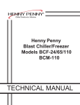
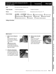
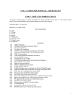
Henny Penny
Heated Holding Cabinet
Model HHC-901
Model HHC-904
TECHNICAL MANUAL
Model HHC-901/904
TABLE OF CONTENTS
Section
Section 1
Page
TROUBLESHOOTING .......................................................................................................
1-1. Introduction ..................................................................................................................
1-2. Safety ..........................................................................................................................
1-3. Test Instrument ............................................................................................................
1-4. Troubleshooting ............................................................................................................
1-5. Error Codes .................................................................................................................
Wiring Diagrams ..........................................................................................................
1-1
1-1
1-1
1-2
1-2
1-5
1-6
Section 2. PARTS INFORMATION .....................................................................................................
2-1. Introduction ..................................................................................................................
2-2. Genuine Parts ..............................................................................................................
2-3. When Ordering Parts ..................................................................................................
2-4. Prices ...........................................................................................................................
2-5. Delivery .......................................................................................................................
2-6. Warranty ......................................................................................................................
2-7. Recommended Spare Parts for Distributors ...............................................................
2-1
2-1
2-1
2-1
2-1
2-1
2-1
2-1
FM06-043
Revised 12-10-09
1209
i
Model HHC-901/904
SECTION 1. TROUBLESHOOTING
1-1. INTRODUCTION
This section provides troubleshooting information in the form of an
easy to read table.
If a problem occurs during the first operation of a new cabinet.
1-2. SAFETY
Where information is of particular importance or is safety related,
the words NOTICE, CAUTION, or WARNING are used. Their
usage is described below.
SAFETY ALERT SYMBOL is used with DANGER,
WARNING, or CAUTION which indicates a personal injury
type hazard.
NOTICE is used to highlight especially important information.
CAUTION used without the safety alert symbol indicates
a potentially hazardous situation which, if not avoided, may
result in property damage.
CAUTION indicates a potentially hazardous situation
which, if not avoided, may result in minor or moderate
injury.
The word WARNING is used to alert you to a procedure,
that if not performed properly, might cause personal
injury.
1-1
1209
Model HHC-901/904
You may use two test instruments to check the electrical
components.
1-3. TEST INSTRUMENTS
1. A voltmeter
2. An ohmmeter.
When the manual refers to the circuit being closed, the ohmmeter
should read zero unless otherwise noted. When the manual refers
to the circuit being open, the ohmmeter will read infinite resistance.
Do not use an ohmmeter to check solid state relays. Use a
voltmeter as decribed in the Troubleshooting Section.
1-4. TROUBLESHOOTING
PROBLEM
With power switch in
POWER position, unit
is completely
inoperative (no power)
To isolate a malfunction, proceed as follows:
1. Clearly define the problem (or symptom) and when it
occurs.
2.
Locate the problem in the troubleshooting table.
3.
Review all possible causes. Then, one-at-a-time work
through the list of corrections until the problem is solved.
CAUSE
• Open circuit
CORRECTION
• Check to see that unit is
plugged in
• Check breaker or fuse at
supply box
• Check voltage at wall
receptacle
• Check POWER switch;
replace if defective
• Check internal component connectors,
and the cord and plug, for loose
connections
1209
• Transformer defective
• Check input and output voltage;
replace if defective
• Control board defective
• Check for 12 volt input from
transformer; if control board shows
12 volts, replace control board
1-2
Model HHC-901/904
1-4. TROUBLESHOOTING (Continued)
PROBLEM
CAUSE
CORRECTION
OPERATION
A.Product not
holding
temperature
• Doors are left open
• Keep doors closed except to
load and unload product
• Temperature set too low
• Increase temperature per instructions in
Operator’s Manual
• Gasket torn or worn
• Replace gasket per
• Heater not working
• Check heater; replace Heater if needed
• Blower not working
• Check blower; replace Blower if needed
• Product held too long
• Hold product only for recommended
time
• Low or improper voltage
• Using meter, compare receptacle voltage
to data plate voltage
B.Cabinet
steaming product
becoming
soggy
• Too much humidity inside the cabinet
• Empty water from the water pan
• Holding product too long
• Hold product for recommended time
C.Product dry
• No water in pan
• Remove pan and put in approximately 1"
of hot water
HEATING SYSTEM
A.Unit will
not heat
1-3
• Faulty control
• Change control PCB if needed
• Faulty high limit
• Check high limit and replace if needed
• Faulty heater
• Check heater and replace if needed
• Faulty wiring
• Check wiring for loose connections
or broken wires and repair as
necessary
1209
Model HHC-901/904
1-4. TROUBLESHOOTING (Continued)
PROBLEM
CAUSE
CORRECTION
HEATING SYSTEM (Continued)
B.Unit will not
heat to
desired
temperature
C.Unit
overheating
1209
• Faulty blower
• Check blower and replace if needed
• Display not indicating
true temperature
• Check probe calibration and
change calibration or offset
if necessary
• One of heaters defective
• Check heater and replace if needed
• Doors being left open too much
• Only open doors as necessary
• Gaskets torn or worn
• Replace gasket
• Defective high limit on one of heaters
• Check high limit and replace if needed
• Faulty control
• Replace control PCB if needed
• Faulty blower
• Check blowers and replace if needed
1-4
Model HHC-901/904
1-5. ERROR CODES
DISPLAY
1-5
CAUSE
PANEL BOARD CORRECTION
“E-4”
Control board
overheating
Turn switch to OFF position, then turn switch back to
ON; if display shows “E-4”, the control board is
getting too hot; make sure unit is not overheating; if
control board is not overheating and “E-4” persists,
replace control board
“E-6”
Faulty temperature
probe
Turn switch to OFF position, then turn switch back to
ON; if “E-6” still shows, have temperature probe
checked
“E-41”
Memory scrambled
Turn switch to OFF position, then turn switch back
to ON; if “E-41” still shows, have the controls
intitialized; if display still shows “E-41”, replace
control board
“E-5”
Unit over-heating;
faulty relay or
control board
If control board doesn’t cut power to relay when the
LED is green, then replace control board; but if
control board does cut power to relay when the
LED is green, but unit continues to heat, check relay
“E-50”
RAM failure
Turn switch to OFF position, then back to
ON; if “E-50” reappears, replace control board
“E-51”
NOVRAM failure
Turn switch to OFF position, then back to
ON; if “E-51” reappears, replace control board
“E-53”
EPROM failure
Turn switch to OFF position, then back to
ON; if “E-53” reappears, replace control
board
1209
Model HHC-901/904
WIRING DIAGRAMS
CDT CONTROLS - 120V
1209
1-6
Model HHC-901/904
WIRING DIAGRAMS
SIMPLE CONTROLS - 120V
1-7
1209
Model HHC-901/904
LIMITED WARRANTY FOR HENNY PENNY EQUIPMENT
Subject to the following conditions, Henny Penny Corporation makes the following limited warranties to the original
purchaser only for Henny Penny appliances and replacement parts:
NEW EQUIPMENT: Any part of a new appliance, except baskets, lamps, and fuses, which proves to be defective in
material or workmanship within two (2) years from date of original installation, will be repaired or replaced without
charge F.O.B. factory, Eaton, Ohio, or F.O.B. authorized distributor. Baskets will be repaired or replaced for ninety (90)
days from date of original installation. Lamps and fuses are not covered under this Limited Warranty. To validate this
warranty, the registration card for the appliance must be mailed to Henny Penny within ten (10) days after installation.
FILTER SYSTEM: Failure of any parts within a fryer filter system caused by the use of the non-OEM filters or
other unapproved filters is not covered under this Limited Warranty.
REPLACEMENT PARTS: Any appliance replacement part, except lamps and fuses, which proves to be defective in
material or workmanship within ninety (90) days from date of original installation will be repaired or replaced without
charge F.O.B. factory, Eaton, Ohio, or F.O.B. authorized distributor.
The warranty for new equipment covers the repair or replacement of the defective part and includes labor charges and
maximum mileage charges of 200 miles round trip for a period of one (1) year from the date of original installation.
The warranty for replacement parts covers only the repair or replacement of the defective part and does not include any
labor charges for the removal and installation of any parts, travel, or other expenses incidental to the repair or replacement of
a part.
EXTENDED FRYPOT WARRANTY: Henny Penny will replace any frypot that fails due to manufacturing or workmanship
issues for a period of up to seven (7) years from date of manufacture. This warranty shall not cover any frypot that fails due to
any misuse or abuse, such as heating of the frypot without shortening.
0 TO 3 YEARS:
During this time, any frypot that fails due to manufacturing or workmanship issues will
be replaced at no charge for parts, labor, or freight. Henny Penny will either install a new frypot at no cost or
provide a new or reconditioned replacement fryer at no cost.
3 TO 7 YEARS:
During this time, any frypot that fails due to manufacturing or workmanship issues will
be replaced at no charge for the frypot only. Any freight charges and labor costs to install the new frypot as
well as the cost of any other parts replaced, such as insulation, thermal sensors, high limits, fittings, and
hardware, will be the responsibility of the owner.
Any claim must be presented to either Henny Penny or the distributor from whom the appliance was purchased. No
allowance will be granted for repairs made by anyone else without Henny Penny’s written consent. If damage occurs during
shipping, notify the sender at once so that a claim may be filed.
THE ABOVE LIMITED WARRANTY SETS FORTH THE SOLE REMEDY AGAINST HENNY PENNY FOR ANY BREACH
OF WARRANTY OR OTHER TERM. BUYER AGREES THAT NO OTHER REMEDY (INCLUDING CLAIMS FOR ANY INCIDENTAL OR CONSEQUENTIAL DAMAGES) SHALL BE AVAILABLE.
The above limited warranty does not apply (a) to damage resulting from accident, alteration, misuse, or abuse; (b) if the
equipment’s serial number is removed or defaced; or (c) for lamps and fuses. THE ABOVE LIMITED WARRANTY IS EXPRESSLY IN LIEU OF ALL OTHER WARRANTIES, EXPRESS OR IMPLIED, INCLUDING MERCHANTABILITY AND FITNESS, AND ALL OTHER WARRANTIES ARE EXCLUDED. HENNY PENNY NEITHER ASSUMES NOR AUTHORIZES ANY
PERSON TO ASSUME FOR IT ANY OTHER OBLIGATION OR LIABILITY.
Revised 01/01/07
1209
1-8
Model HHC-901/904
SECTION 2. PARTS INFORMATION
2-1. INTRODUCTION
This section lists the replaceable parts of the Henny Penny
HHC-901 & HHC-904 units.
2-2. GENUINE PARTS
Use only genuine Henny Penny parts in your cabinet. Using
a part of lesser quality or substitute design may result in
damage to the unit, or personal injury.
2-3. WHEN ORDERING PARTS
Once the parts that you want to order have been found in the
parts list, write down the following information:
Example:
Item Number
Part Number
Description
8
27149
STOP - DOOR
From data plate, list the following information:
Example:
Product Number
Serial Number
Voltage
HHC901.0
AW001IE
120 Volt
2-4. PRICES
Your distributor has a price list and will be glad to inform
you of the cost of your parts order.
2-5. DELIVERY
Commonly replaced items are stocked by your local
distributor and will be sent out when your order is received.
Other parts will be ordered, by your distributor, from Henny
Penny Corporation.
2-6. WARRANTY
All replacement parts (except lamps and fuses) are warranted
for 90 days against manufacturing defects and workmanship.
If damage occurs during shipping, notify the carrier at once
so that a claim may be properly filed. Refer to warranty in
the front of the manual for other rights and limitations.
2-7. RECOMMENDED
SPARE PARTS FOR
DISTRIBUTORS
Recommended replacement parts, stocked by your distributor, are
indicated with √ in the parts lists. Please use care when ordering
recommended parts, because all voltages and variations are
marked. Distributors should order parts based upon common
voltages and equipment sold in their territory.
2-1
1209
Model HHC-901/904
1
2
10
3
7
4
8
6
5
9
11
1209
2-2
Item No.
√
√
√
√
√
√
√
√
√
√
2-3
1
2
2
3*
3*
3
3
3
3
4
4
4*
5
5
6
7
8
9
9
9*
9*
10
11
11
12*
Part No.
67472
79906
81963
77741
83742
81927
79997
81921
77742
77789-001
77789-004
77789-002
77789-003
77789-005
14272
14271
27149
81258
26120
27154
27155
80002
81310
83818
67794
Description
ASSY-POWER CORD 120/20A STR
DECAL-REAR CONT 13CDT 901
DECAL-REAR CONTROL 6CDT 904
ASSY-DOOR RH SS 2B HC901/904
ASSY-DOOR LH SS 2B HC901/904
ASSY-DOOR FLIP LH HC904
ASSY-DOOR FLIP RH HC904
ASSY-DOOR FLIP LH HC901
ASSY-DOOR FLIP RH HC901
PANEL-FLIP DOOR 7.610 HGT MIDDLE - 901
PANEL-FLIP DOOR 11.875 HGT TOP - 904
PANEL-FLIP DOOR 8.062 HGT TOP- 901
PANEL-FLIP DOOR 7.485 HGT BOT - 901
PANEL-FLIP DOOR 11.875 HGT BOT - 904
KIT - LATCH
KIT - HINGE
STOP – DOOR
ASSY-LEG 4 INCH
26120 FOOT – ADJUSTABLE
CASTER - 5 IN. - LOCKING
CASTER - 5 IN.
SEAL-DOOR FLIP HC901/904
DISPLAY - HC90X REAR 13 CDT
DISPLAY - HC90X REAR 6 CDT
ASSY-FLIP SHELF
Quantity
1
1
1
AR
AR
AR
AR
AR
AR
AR
AR
AR
AR
AR
1/DOOR
2/DOOR
AR
4
4
4
4
1/DOOR
1
1
1
1209
1
2
7
3
4
6
5
Item No.
√
√
√
√
√
√
√
1
1
1*
2
3
4
5
5
6
7
Part No.
79500
81960
77755
72277
29523
ME70-001
83758
83759
40645
30978
Description
DECAL- CONTROL PANEL 13CDT 901
DECAL- CONTROL PANEL 6CDT 904
DECAL - CONTROL PANEL - SIMPLE
SWITCH - POWER - SPLASH PROOF
ASSEMBLY - RTD PROBE
BUZZER - PIEZO
CONTROL - 90X - 13 CDT SINGLE BOARD
CONTROL - 90X - 6 CDT SINGLE BOARD
RELAY - 25A - SOLID STATE
TRANSFORMER - 120VP-12VS-20VA
Quantity
1
1
1
1
1
1
1
1
1
1
*not shown
1209
2-4
1
2
3
Item No.
√ 1
√ 2
√ 3
4*
Part No.
63363
51278
18201
63360
Description
Quantity
BLOWER - MOTOR - 120V
HEATER - COIL - 750W - 120V
SENSOR - HIGHT LIMIT - 335 DEG
FAN BLADE
1
1
1
1
*not shown
2-5
1209
1
2
3
Item No.
1
1
1
2
3
1209
Part No.
77774
77776
80044
77768
71478
70381
25646
25685
LW02-005
NS03-030
Description
Quantity
ASSY - AIR DUCT - LOWER - 901
ASSY - AIR DUCT - UPPER - 901
ASSY - AIR DUCT - 904
GASKET - DOOR - 901/904
WATER BOX ASSEMBLY
WATER BOX & STUD ASSY
WIPER
PULL
LOCKWASHER -INTERNAL #10
NUT - ACORN #10-32
2
2
2
1/DOOR
1
1
1
1
2
2
2-6