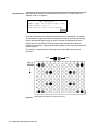
1
Thermal Cycler Temperature Verification System For GeneAmp® PCR Systems 2400, 9600, 9700 User’s Manual © Copyright 2001, Applied Biosystems. All rights reserved. For Research Use Only. Not for use in diagnostic procedures. ABI PRISM and the ABI PRISM design, AmpErase, Applied Biosystems, Aquapore, AmpliCover, Anitron, Biobytes, Brownlee, FastPhoramidite, GeneScan, Genotyper, HLP, INHERIT, Masterpiece, MicroAmp, MicroCoat, MPLC, NEWGUARD, ONESTEP, OPC, PCR-MATE, Phosphalink, POLYPORE, Precipitette, ProBlott, PROCISE, ProFocus, ProSort, ProSpin, SeqEd, Sequence Navigator, SPHERI5, SPHERI10, StockMarks, Stretch, Synergy, SynthAssist, TaqMan and VeloSep are registered trademarks of Applera Corporation or its subsidiaries in the U.S. and certain other countries. ABI, AmpFlSTR, AutoAssembler, BaseSprinter, CATALYST, GeneAssist, LV40, MatchMaker, PDQ, Primer Express and ProSorb are trademarks of Applera Corporation or its subsidiaries in the U.S. and certain other countries. AmpliTaq, EnviroAmp, and GeneAmp are registered trademarks, and AmpliTaq Gold is a trademark, of Roche Molecular Systems, Inc. All other trademarks are the sole property of their respective owners. Contents 1 Temperature Verification System Overview . . . . . . . . . . . . . . . . . 1-1 Introduction . . . . . . . . . . . . . . . . . . . . . . . . . . . . . . . . . . . . . . . . . . . . . . . . . . . . . . . . . . . . . . . . 1-1 Using the Digital Thermometer . . . . . . . . . . . . . . . . . . . . . . . . . . . . . . . . . . . . . . . . . . . . . . . . . 1-2 Getting the Temperature Verification System Recalibrated . . . . . . . . . . . . . . . . . . . . . . . . . . . . 1-6 Technical Support . . . . . . . . . . . . . . . . . . . . . . . . . . . . . . . . . . . . . . . . . . . . . . . . . . . . . . . . . . . . 1-9 2 Temperature Verification Tests for the 2400 . . . . . . . . . . . . . . . . 2-1 Temperature Verification Tests . . . . . . . . . . . . . . . . . . . . . . . . . . . . . . . . . . . . . . . . . . . . . . . . . . 2-1 Preparation of the RTD Probe Assembly . . . . . . . . . . . . . . . . . . . . . . . . . . . . . . . . . . . . . . . . . . 2-2 Temperature Calibration Verification Test . . . . . . . . . . . . . . . . . . . . . . . . . . . . . . . . . . . . . . . . . 2-4 Temperature Non-Uniformity Test . . . . . . . . . . . . . . . . . . . . . . . . . . . . . . . . . . . . . . . . . . . . . . . 2-9 3 Temperature Verification Tests for the 9600 . . . . . . . . . . . . . . . . 3-1 Temperature Verification Tests . . . . . . . . . . . . . . . . . . . . . . . . . . . . . . . . . . . . . . . . . . . . . . . . . . 3-1 Test Results. . . . . . . . . . . . . . . . . . . . . . . . . . . . . . . . . . . . . . . . . . . . . . . . . . . . . . . . . . . . . . . . . 3-8 The Temperature Uniformity Test . . . . . . . . . . . . . . . . . . . . . . . . . . . . . . . . . . . . . . . . . . . . . . 3-10 4 Temperature Verification Tests for the 9700 . . . . . . . . . . . . . . . . 4-1 Temperature Verification Tests . . . . . . . . . . . . . . . . . . . . . . . . . . . . . . . . . . . . . . . . . . . . . . . . . . 4-1 The RTD Probe Assembly . . . . . . . . . . . . . . . . . . . . . . . . . . . . . . . . . . . . . . . . . . . . . . . . . . . . . 4-2 The Calibration Verification Test . . . . . . . . . . . . . . . . . . . . . . . . . . . . . . . . . . . . . . . . . . . . . . . . 4-3 The Temperature Non-Uniformity Test . . . . . . . . . . . . . . . . . . . . . . . . . . . . . . . . . . . . . . . . . . . 4-8 iii Temperature Verification System Overview 1 1 Introduction Tests Performed Use the Temperature Verification System to perform the following tests on your GeneAmp PCR Systems: ♦ Temperature Calibration Verification Test ♦ Temperature Uniformity Test Parts Included Note Carefully unpack the kit and check the parts included against the following list. If any part is damaged or missing, contact the shipping carrier and Applied Biosystems immediately. ♦ Digital Thermometer with 9V battery installed ♦ RTD Probe Assembly ♦ Cotton swabs (P/N 401–0066) ♦ Light Mineral Oil (P/N 186–2302) ♦ Probe Trays: – 2400 (P/N N8031076) – 9600 (P/N N801–3837) – 9700 (P/N N8050305) Your RTD probe and digital thermometer have been calibrated together at the IMPORTANT factory. Therefore, do not use the probe or digital thermometer with any other probe or digital thermometer; they are not interchangeable. Temperature Verification System Overview 1-1 Using the Digital Thermometer Overview The handheld digital thermometer (Figure 1) is used with a platinum resistance temperature device (RTD) probe to verify that your thermal cycler is still within calibration tolerance. It is also used to test the uniformity of your instrument's sample block. The digital thermometer has a temperature range of -10 to 110 °C and is accurate to within +/-0.3 °C. Do not try to recalibrate or perform any service on the digital thermometer. IMPORTANT The only user-serviceable component in the unit is the battery. Instructions Observe the following when using the digital thermometer: ♦ Make sure the RTD probe is connected to the input connector located at the top of the digital thermometer. ♦ To turn on the digital thermometer, move the on/off range switch to the 200 position. IMPORTANT Do not use the 630 range. ♦ The temperature measured by the RTD probe appears on the digital thermometer display in degrees Celsius. ♦ When you complete the test, move the ON–OFF/RANGE switch to the OFF position. 1-2 Temperature Verification System Overview LO BAT ˚C 630 200 OFF 42 V MAX GR1092 100Ω PLATINUM RTD α = 0.00385 Figure 1 Front view of digital thermometer Temperature Verification System Overview 1-3 Replacing the The digital thermometer is powered by a 9V battery, which has been installed at the Battery factory. If the battery is low, the “LO BAT" indicator will appear on the display. Install a new battery immediately if the “LO BAT" indicator appears. To replace the battery: Step Action 1 Remove the three 7/16-in. long screws securing the back cover of the digital thermometer (Figure 2). 2 Install the 9 V battery as shown in Figure 2. Make sure the battery terminals are contacting the battery clips. 3 Replace the back cover and secure it with the three screws removed in step 1. + – GR1093 Figure 2 Digital thermometer shown with back cover removed 1-4 Temperature Verification System Overview Temperature Display The sample temperature display on the instrument will be different than the display on Differences the digital thermometer during heating or cooling transitions. This is because the digital thermometer measures block temperature while the thermal cycler measures sample temperature. The instrument sample temperature display is a function of the tube type and the reaction volume. Using the Probe We recommend that you use the RTD probe and digital thermometer only for the While Running temperature calibration verification test and the temperature uniformity test, which are Programs described in these instructions on page 1-2. If you use the RTD probe and digital thermometer while running programs other than those used in the two tests, be aware that the accuracy of the RTD probe will decrease due to the effect of the heated sample block cover. The heated cover normally operates at 105 °C. The effect of the heated cover on the RTD probe decreases as the temperature of the sample block approaches 99.9 °C. Temperature Verification System Overview 1-5 Getting the Temperature Verification System Recalibrated Overview IMPORTANT Do not try to recalibrate or perform any service on the digital thermometer. The only user-serviceable component in the unit is the battery. We recommend that your Temperature Verification System be recalibrated once a year. In the United States If you are in the United States or Canada, get your Temperature Verification System and Canada serviced by calling the Applied Biosystems Service Repair Center at (800) 831-6844. The Service Repair Center will give you a Return Authorization Number and an address to which you can send your Temperature Verification System. Outside the United If you are outside the United States, call your local Applied Biosystems Sales/Service States and Canada office. See page 1-10 for a listing of Sales offices, and their telephone and Fax numbers. When shipping your Temperature Verification System, ship the meter and IMPORTANT probe in the black case provided, and enclose a Decontamination Certificate. Decontaminating Decontaminate the temperature probe by gently swabbing the probe cone with a The Temperature cotton swab, using a 20% Clorox/80% water mixture. Observe the following Probe precautions when decontaminating your probe: ♦ Do not submerge the probe in Clorox. ♦ Do not disassemble the the probe assembly. ♦ Do not separate the cones. 1-6 Temperature Verification System Overview CERTIFICATE OF DECONTAMINATION Return Authorization: 1. This document must be completed in full, signed by the customer/operator of all Applied Biosystems equipment, and handled as follows: ♦ Attach to all Applied Biosystems products prior to returning to either a Applied Biosystems manufacturing facility, Field Office, or Service Repair Center for the purpose of repair, refurbishing, trade in, or replacement. ♦ Provide to all Applied Biosystems Representatives before they perform service on any Applied Biosystems equipment which has been located within a biological or radioactive materials laboratory. Instrument/model/type: ____________________________________________________ Instrument serial number: ____________________________________________________ Reason for return/service: ____________________________________________________ RMA or RAN number: ____________________________________________________ Decontamination Information and Procedure: 1. Has this product been exposed to any infectious agents assigned to biosafety levels 2, 3, or 4 ? ____________________________________________________ If so, please indicate agent and biosafety hazard class: ____________________________________________________ 2. Has this product been exposed to toxic, carcinogenic, or radioactive substances? ____________________________________________________ If so, please indicate types and quantities used: ____________________________________________________ 3. Indicate how the equipment was cleaned or disinfected by checking one or more of the decontamination procedures described below: Contact with infectious agents: ♦ The equipment was thoroughly decontaminated by spraying it or wiping it down with a 1:10 dilution of Clorox brand bleach, or equivalent, with water. ♦ The disinfectant remained on the unit for a minimum of 10 minutes before flushing with water. Temperature Verification System Overview 1-7 Contact with radioactive material: ♦ The equipment was thoroughly decontaminated by spraying it or wiping it down with a commercially available decontaminate (i.e., Radiacwash) or equivalent. ♦ The instrument must be surveyed with a Geiger meter and swipe tested with a scintillation counter. Results must be attached to this form. Chemical contamination: ♦ All chemical bottles have been removed from the instrument. ♦ The equipment was thoroughly decontaminated by rinsing areas associated with chemicals with a solvent such as alcohol or water. Chemical contamination to valve blocks: The valve block was flushed and dried with appropriate gas (argon, helium, or nitrogen). In the event that a valve block cannot be flushed properly, label it as a HAZARDOUS WASTE SOLID and dispose of it in accordance with all local, state, federal and environmental health regulation and laws. Other: Please describe how equipment was cleaned or disinfected. Attach additional paper, if necessary. ___________________________________________________________________ ___________________________________________________________________ ___________________________________________________________________ By accepting authorization to return this product, I assume all responsibility and liability for biological, chemical, and radiological decontamination and cleaning. I understand that Applied Biosystems has no obligation to repair or service any product unless adequate information is provided to ensure the safety of all personnel handling the exposed product. Print Name:_________________________________Title:_________________________ Company/Institution: ____________________ Phone Number:_________________ Signature: ____________________________Date: ______________ Fax Number___________________ 1-8 Temperature Verification System Overview Technical Support Contacting You can contact Applied Biosystems for technical support by telephone or fax, by Technical Support e-mail, or through the Internet. You can order Applied Biosystems user documents, MSDSs, certificates of analysis, and other related documents 24 hours a day. In addition, you can download documents in PDF format from the Applied Biosystems Web site (please see the section “To Obtain Documents on Demand” following the telephone information below). To Contact Technical Contact technical support by e-mail for help in the following product areas: Support by E-Mail Product Area E-mail address Genetic Analysis (DNA Sequencing) [email protected] Sequence Detection Systems and PCR [email protected] Protein Sequencing, Peptide and DNA Synthesis [email protected] Biochromatography, PerSeptive DNA, PNA and Peptide Synthesis systems, CytoFluor®, FMAT™, Voyager™, and Mariner™ Mass Spectrometers [email protected] LC/MS (Applied Biosystems/MDS Sciex) [email protected] or [email protected] Chemiluminescence (Tropix) [email protected] Hours for Telephone In the United States and Canada, technical support is available at the following times: Technical Support Product Hours Chemiluminescence 8:30 a.m. to 5:30 p.m. Eastern Time Framingham support 8:00 a.m. to 6:00 p.m. Eastern Time All Other Products 5:30 a.m. to 5:00 p.m. Pacific Time To Contact Technical In North America Support by To contact Applied Biosystems Technical Support, use the telephone or fax numbers Telephone or Fax given below. (To open a service call for other support needs, or in case of an emergency, dial 1-800-831-6844 and press 1.) Product or Product Area Telephone Dial... Fax Dial... ABI PRISM® 3700 DNA Analyzer 1-800-831-6844, then press 8 1-650-638-5981 DNA Synthesis 1-800-831-6844, then press 21 1-650-638-5981 Fluorescent DNA Sequencing 1-800-831-6844, then press 22 1-650-638-5981 Fluorescent Fragment Analysis (includes GeneScan® applications) 1-800-831-6844, then press 23 1-650-638-5981 Temperature Verification System Overview 1-9 Product or Product Area Telephone Dial... Fax Dial... Integrated Thermal Cyclers (ABI PRISM ® 877 and Catalyst 800 instruments) 1-800-831-6844, then press 24 1-650-638-5981 ABI PRISM ® 3100 Genetic Analyzer 1-800-831-6844, then press 26 1-650-638-5981 BioInformatics (includes BioLIMS, BioMerge™, and SQL GT™ applications) 1-800-831-6844, then press 25 1-505-982-7690 Peptide Synthesis (433 and 43X Systems) 1-800-831-6844, then press 31 1-650-638-5981 Protein Sequencing (Procise Protein Sequencing Systems) 1-800-831-6844, then press 32 1-650-638-5981 PCR and Sequence Detection 1-800-762-4001, then press 1 for PCR, 2 for the 7700 or 5700, 6 for the 6700 or dial 1-800-831-6844, then press 5 1-240-453-4613 Voyager MALDI-TOF Biospectrometry and Mariner ESI-TOF Mass Spectrometry Workstations 1-800-899-5858, then press 13 1-508-383-7855 Biochromatography (BioCAD Workstations and Poros Perfusion Chromatography Products) 1-800-899-5858, then press 14 1-508-383-7855 Expedite Nucleic acid Synthesis Systems 1-800-899-5858, then press 15 1-508-383-7855 Peptide Synthesis (Pioneer and 9050 Plus Peptide Synthesizers) 1-800-899-5858, then press 15 1-508-383-7855 PNA Custom and Synthesis 1-800-899-5858, then press 15 1-508-383-7855 FMAT 8100 HTS System and Cytofluor 4000 Fluorescence Plate Reader 1-800-899-5858, then press 16 1-508-383-7855 Chemiluminescence (Tropix) 1-800-542-2369 (U.S. 1-781-275-8581 only), or 1-781-271-0045 Applied Biosystems/MDS Sciex 1-800-952-4716 1-650-638-6223 Telephone Dial... Fax Dial... Outside North America Region Africa and the Middle East Africa (English Speaking) and West Asia (Fairlands, South Africa) 27 11 478 0411 27 11 478 0349 South Africa (Johannesburg) 27 11 478 0411 27 11 478 0349 Middle Eastern Countries and North Africa (Monza, Italia) 39 (0)39 8389 481 39 (0)39 8389 493 1-10 Temperature Verification System Overview Telephone Dial... Region Fax Dial... Eastern Asia, China, Oceania Australia (Scoresby, Victoria) 61 3 9730 8600 61 3 9730 8799 China (Beijing) 86 10 64106608 86 10 64106617 Hong Kong 852 2756 6928 852 2756 6968 Korea (Seoul) 82 2 593 6470/6471 82 2 593 6472 Malaysia (Petaling Jaya) 60 3 758 8268 60 3 754 9043 Singapore 65 896 2168 65 896 2147 Taiwan (Taipei Hsien) 886 2 22358 2838 886 2 2358 2839 Thailand (Bangkok) 66 2 719 6405 66 2 319 9788 Europe Austria (Wien) 43 (0)1 867 35 75 0 43 (0)1 867 35 75 11 Belgium 32 (0)2 712 5555 32 (0)2 712 5516 Czech Republic and Slovakia (Praha) 420 2 61 222 164 420 2 61 222 168 Denmark (Naerum) 45 45 58 60 00 45 45 58 60 01 Finland (Espoo) 358 (0)9 251 24 250 358 (0)9 251 24 243 France (Paris) 33 (0)1 69 59 85 85 33 (0)1 69 59 85 00 Germany (Weiterstadt) 49 (0) 6150 101 0 49 (0) 6150 101 101 Hungary (Budapest) 36 (0)1 270 8398 36 (0)1 270 8288 Italy (Milano) 39 (0)39 83891 39 (0)39 838 9492 Norway (Oslo) 47 23 12 06 05 47 23 12 05 75 Poland, Lithuania, Latvia, and Estonia (Warszawa) 48 (22) 866 40 10 48 (22) 866 40 20 Portugal (Lisboa) 351 (0)22 605 33 14 351 (0)22 605 33 15 Russia (Moskva) 7 095 935 8888 7 095 564 8787 South East Europe (Zagreb, Croatia) 385 1 34 91 927 385 1 34 91 840 Spain (Tres Cantos) 34 (0)91 806 1210 34 (0)91 806 1206 Sweden (Stockholm) 46 (0)8 619 4400 46 (0)8 619 4401 Switzerland (Rotkreuz) 41 (0)41 799 7777 41 (0)41 790 0676 The Netherlands (Nieuwerkerk a/d IJssel) 31 (0)180 331400 31 (0)180 331409 United Kingdom (Warrington, Cheshire) 44 (0)1925 825650 44 (0)1925 282502 All other countries not listed (Warrington, UK) 44 (0)1925 282481 44 (0)1925 282509 Japan Japan (Hacchobori, Chuo-Ku, Tokyo) 81 3 5566 6230 81 3 5566 6507 Latin America Del.A. Obregon, Mexico 305-670-4350 305-670-4349 Temperature Verification System Overview 1-11 To Reach Technical We strongly encourage you to visit our Web site for answers to frequently asked Support Through questions and for more information about our products. You can also order technical the Internet documents or an index of available documents and have them faxed or e-mailed to you through our site. The Applied Biosystems Web site address is http://www.appliedbiosystems.com/techsupp To submit technical questions from North America or Europe: Step Action 1 Access the Applied Biosystems Technical Support Web site. 2 Under the Troubleshooting heading, click Support Request Forms, then select the relevant support region for the product area of interest. 3 Enter the requested information and your question in the displayed form, then click Ask Us RIGHT NOW (blue button with yellow text). 4 Enter the required information in the next form (if you have not already done so), then click Ask Us RIGHT NOW. You will receive an e-mail reply to your question from one of our technical experts within 24 to 48 hours. To Obtain Free, 24-hour access to Applied Biosystems technical documents, including MSDSs, Documents on is available by fax or e-mail or by download from our Web site. Demand To order documents... Then... by index number a. Access the Applied Biosystems Technical Support Web site at http://www.appliedbiosystems.com/techsupp b. Click the Index link for the document type you want, then find the document you want and record the index number. c. Use the index number when requesting documents following the procedures below. by phone for fax delivery a. From the U.S. or Canada, call 1-800-487-6809, or from outside the U.S. and Canada, call 1-858-712-0317. b. Follow the voice instructions to order the documents you want. Note through the Internet for fax or e-mail delivery There is a limit of five documents per request. a. Access the Applied Biosystems Technical Support Web site at http://www.appliedbiosystems.com/techsupp b. Under Resource Libraries, click the type of document you want. c. Enter or select the requested information in the displayed form, then click Search. d. In the displayed search results, select a check box for the method of delivery for each document that matches your criteria, then click Deliver Selected Documents Now (or click the PDF icon for the document to download it immediately). e. Fill in the information form (if you have not previously done so), then click Deliver Selected Documents Now to submit your order. Note There is a limit of five documents per request for fax delivery but no limit on the number of documents you can order for e-mail delivery. 1-12 Temperature Verification System Overview Temperature Verification Tests for the 2400 2 2 Temperature Verification Tests Types of Tests ♦ ♦ Calibration Verification tests the sample block against temperature accuracy specifications. Temperature Non-Uniformity tests the temperature uniformity in the sample block. System Contents Equipment Required The Temperature Verification System is required to perform these tests. The Temperature Verification System should include the following: ♦ Digital thermometer with 9V battery installed ♦ RTD probe ♦ Cotton swabs ♦ Light mineral oil ♦ 2400 probe tray Refer to the instructions included with your Temperature Verification System IMPORTANT for a detailed description of digital thermometer operation. Temperature Verification Tests for the 2400 2-1 Preparing the RTD Probe Assembly for Tests Description The RTD Probe Assembly consists of two cones, one of which measures the temperature of the sample well. The wire is attached to the cone that does not measure the temperature of the sample well. This cone is a dummy probe. Probe in B4 Dummy Probe in B5 Probe Assembly Probe Tray Thread probe wires through notch. Figure 2-1 Notch (Always faces front) RTD Probe Assembly Preparation ! WARNING ! BURN HAZARD! The sample block is hot to the touch and can cause burns. To prepare the RTD Probe Assembly for the Calibration Verification Test: Step Action 1 If the System 2400 heated cover is in the forward position, lift the lever, then slide the cover back. 2 Using a cotton swab, coat wells B4 and B5 with mineral oil. 3 Place the probe tray on the sample block so that the notch faces the front of the instrument. 4 Place the Probe Assembly into wells B4 and B5 so that the dummy probe sits in B5. 5 Thread the probe wire through the notch in the probe tray. 6 Connect the probe to the digital thermometer. 7 Slide the heated cover forward and pull the lever down. 2-2 Temperature Verification Tests for the 2400 To prepare the RTD Probe Assembly for the Calibration Verification Test: Step 8 Action Turn on the digital thermometer by moving the ON-OFF/RANGE switch to the 200 position To prepare the RTD Probe Assembly for the Temperature Non-Uniformity Test Step Action 1 If the System 2400 heated cover is in the forward position, lift the lever, then slide the cover back. 2 Using a cotton swab, coat wells A2 and A3 with mineral oil. 3 Place the probe tray on the sample block so that the notch faces the front of the instrument. 4 Place the Probe Assembly into wells A2 and A3 so that the dummy probe sits in A3. 5 Thread the probe wire through the notch in the Probe tray (Figure 2-1). 6 Connect the probe to the digital thermometer. 7 Slide the heated cover forward and pull the lever down. 8 Turn on the digital thermometer by moving the ON-OFF/RANGE switch to the 200 position. Temperature Verification Tests for the 2400 2-3 Temperature Calibration Verification Test Overview The RTD probe and the digital thermometer are used to take temperature readings of one sample well at three different setpoint temperatures: ♦ 92 °C ♦ 56 °C ♦ 20 °C Description of the When the Calibration Verification Test begins, the block and heated cover each move Beginning Test toward the first setpoint of 92 °C. The block temperature will increase and the cover Functions temperature decrease. After the heated cover reaches 92 °C and the block reaches the temperature of the heated cover + 10 °C, the instrument pauses three minutes to stabilize the temperature. ! WARNING ! BURN HAZARD! The sample block is hot to the touch and can cause burns. The Stabilizing at Setpoint screen appears. This is the start of the 3 minute stabilization period. Figure 2-2 Stabilizing at Setpoint Screen When three minutes have elapsed, the Setpoint screen will be displayed (Figure 2-3). The digital thermometer reading of the sample well temperature is entered into the Enter Actual Temp field. This process is repeated at each of the three setpoints. Figure 2-3 Setpoint screen for entry of digital thermometer readings 2-4 Temperature Verification Tests for the 2400 Performing the Temperature To perform the first segment of the calibration test: Calibration Verification Test Step Action 1 From the Diagnostics screen, press F3-TmpVer. This displays the Temperature Verification screen. 2 Press F1-Temp. This displays the Calibration Setup screen. This screen instructs you to set up the RTD probe assembly. 3 After installing the probe assembly, slide the heated cover forward and pull the lever down. 4 Press F1-Run to initiate the Calibration Verification Test. This automatically verifies the temperature of the sample block, and displays the Setpoint Values screen. Note To exit the test at any time, press F5-Cancel Temperature Verification Tests for the 2400 2-5 To perform the first segment of the calibration test: (continued) Step Action 5 When the temperature stabilizes at 92 °C and the counter decrements to zero, read the digital thermometer. 6 Use the numeric keys to type the value displayed on the digital thermometer into the highlighted Enter actual block temperature field. 2-6 Temperature Verification Tests for the 2400 To perform the second segment of the calibration test: Step Action 1 Press Enter. This will initiate the second segment of the temperature calibration process. The heated cover and sample block now approach the second setpoint temperature, 56 °C. 2 When the temperature stabilizes at 56 °C and the counter decrements to zero, read the digital thermometer. 3 Use the numeric keys and type the value displayed on the digital thermometer in the highlighted Enter actual block temperature field. 4 Press Enter. This will initiate the third segment of the temperature calibration process. The heated cover and sample block will approach the third setpoint temperature, 20 °C. 5 When the temperature stabilizes at 20 °C and the counter decrements to zero, read the digital thermometer. 6 Use the numeric keys and type the value displayed on the digital thermometer in the highlighted Enter actual block temperature field. 7 Press Enter. This is the last temperature entry. The GeneAmp 2400 displays the digital thermometer measurements in the right hand column of the Calibration Verification screen. 8 Press F1-Accept to accept the calibration or F5-Cancel to cancel the calibration. 9 Turn off the digital thermometer, remove the probe assembly and clean the oil from the sample block. Temperature Verification Tests for the 2400 2-7 Calibration The digital thermometer reading at each setpoint must be +0.30 °C of the instrument Verification setpoint temperature. Specification Values that are out of specification cannot be saved by pressing FI-Accept. 2-8 Temperature Verification Tests for the 2400 Temperature Non-Uniformity Test Overview The Temperature Non-Uniformity test uses the RTD probe assembly and a digital thermometer to test the temperature uniformity of seven different wells (see the list below and Figure 2-4) in the sample block. ♦ A2 ♦ A7 ♦ B1 ♦ B4 ♦ B8 ♦ C2 ♦ C7 These wells are tested at two different setpoint temperatures: ♦ 94 °C ♦ 37 °C Schematic A schematic representation of the Temperature Non-Uniformity Test is shown below. Measure well A2 ~120 seconds into Setpoint #1 Measure well A7 ~120 seconds at Setpoint #1 Measure well A2 ~70 seconds at Setpoint #2 Measure well A7 ~70 seconds at Setpoint #2 94 Temp oC Move the probe to well A7 37 25 Cycle #1 0 Figure 2-4 2 Move the probe to well B1 Cycle #2 3 4.5 6 Time (minutes) The Temperature Non-Uniformity test Temperature Verification Tests for the 2400 2-9 Description of About 90 seconds after the test begins, the Stabilizing at Setpoint screen is displayed Beginning Test (Figure 2-5). Functions Figure 2-5 The Setpoint Screen The instrument pauses 30 seconds to allow the temperature to stabilize. A digital thermometer reading is taken and entered using the numeric keypad. About 40 seconds after the digital thermometer reading is entered, the heated cover and sample block approach the second setpoint value of 37 °C. Again, the instrument pauses 30 seconds to allow the temperature to stabilize. A digital thermometer reading is taken and entered using the numeric keypad. This process is repeated in seven different sample block wells. Figure 2-6 Location of wells used in Temperature Non-Uniformity test 2-10 Temperature Verification Tests for the 2400 Procedure To run the Temperature Non-Uniformity Test: Step Action 1 From the Diagnostics screen, press F3-TmpVer. This displays the Temperature Verification screen. 2 Press F2-TNU to display the TNU Setup screen. This screen instructs you to set up the RTD probe assembly. Both the probe and the dummy probe are moved to seven different Note locations in the block during the Temperature Non-Uniformity test. 3 After installing the probe assembly, slide the heated cover forward and pull the lever down. 4 Press F1-Run to initiate the Temperature Non-Uniformity Test. This displays the TNU Setpoint Values screen. Temperature Verification Tests for the 2400 2-11 To run the Temperature Non-Uniformity Test: Step Action 5 When the temperature stabilizes at 94 °C and the counter decrements to zero, read the digital thermometer. 6 Use the numeric keys to type the temperature displayed on the digital thermometer in the highlighted Enter actual block temperature field. 7 Press Enter. The sample block and heated cover now approach 37 °C. 8 Read the digital thermometer. 9 Use the numeric keys to type the temperature displayed on the digital thermometer in the highlighted Enter actual block temperature field. 10 Press Enter. 11 Slide the heated cover back and move the probe assembly to wells A7 and A6, with the dummy probe in A6, as indicated by the screen shown below. 12 Repeat steps 5 through 10 on wells A7, B1, B4, B8, C2, and C7. Make sure you place the measuring cone of the probe assembly into these wells and the dummy probe into adjacent wells. 2-12 Temperature Verification Tests for the 2400 To run the Temperature Non-Uniformity Test: Step Action 13 When the GeneAmp 2400 completes the Temperature Non-Uniformity Test, it displays the actual values gathered during testing. 14 Press F1-Accept or F5-Cancel. 15 Turn off the digital thermometer, remove the probe assembly from the sample block and clean the oil from the sample block. Temperature The maximum temperature measured in any well at the 94 °C setpoint minus the Non-Uniformity minimum temperature measured in any well at the 94 °C setpoint must be equal to or Specifications less than 1.0 °C. This can be expressed as: Max Temp 94 °C – Min Temp 94 °C < 1.0 °C The maximum temperature measured in any well at the 37 °C setpoint minus the minimum temperature measured in any well at the 37 °C setpoint must be equal to or less than 1.0 °C. This can be expressed as: Max Temp 37 °C – Min Temp 37 °C < 1.0 °C Temperature Verification Tests for the 2400 2-13 Temperature Verification Tests for the 9600 3 3 Temperature Verification Tests Types of Tests ♦ ♦ Calibration Verification tests the sample block against temperature accuracy specifications. Temperature Non-Uniformity tests the temperature uniformity in the sample block. System Contents Equipment Required The Temperature Verification System is required to perform these tests. The Temperature Verification System should includethe following: ♦ Digital thermometer with 9V battery installed ♦ RTD probe ♦ Cotton swabs ♦ Light mineral oil ♦ 2400 probe tray Refer to the instructions included with your Temperature Verification System IMPORTANT for a detailed description of digital thermometer operation. Temperature Verification Tests for the 9600 3-1 Preparation of the ! WARNING ! BURN HAZARD! The sample block is hot to the touch and can cause RTD Probe burns. Assembly To prepare the RTD Probe Assembly for the Calibration Verification Test: Step Action 1 If the the sample block heated cover is in the forward position, turn the knob completely counterclockwise, then slide the cover back. 2 Coat wells D1 and E1 with mineral oil using a cotton swab. The illustration below shows the location of the wells. 1 2 3 4 5 6 7 8 9 10 11 12 A B C D E F H 3 GR1088 G Place the probe tray on the sample block so that the probe tray notch faces the front of the instrument. The RTD probe assembly consists of two cones, one of which measures Note the temperature of the sample well. The wire is attached to the cone that does not measure the temperature of the sample well; this cone is a dummy probe. 3-2 Temperature Verification Tests for the 9600 To prepare the RTD Probe Assembly for the Calibration Verification Test: (continued) Step Action Place the probe assembly into wells D1 and E1 so that the dummy probe sits in D1. Carefully thread the probe wire through the notch in the probe tray. Make sure the probe is connected to the digital thermometer. 5 Slide the heated cover forward, then turn the cover knob clockwise until the white mark on the knob is aligned with the white mark on the cover. GR1170 4 Temperature Verification Tests for the 9600 3-3 The Temperature Calibration To perform the first phase of the calibration test: Verification Test Procedure Step Action 1 Turn on the digital thermometer by moving the ON–OFF/RANGE switch to the 200 position. 2 Turn on the GeneAmp PCR System 9600. The main menu appears: 3 Press the OPTION key three times to move the cursor to UTIL, then press ENTER. The utilities menu appears: 4 Press the OPTION key twice to move the cursor to DIAG, then press ENTER. The following display appears: 5 Run the Verify Calibration Diagnostic Test (Test #5) by pressing 5 then ENTER. To ensure maximum accuracy, the temperatures of the heated cover and Note the sample block are the same in this test. This prevents the heated cover from affecting the accuracy of the RTD probe. The temperature of the sample block and heated cover will go to 40 °C, and the following display will appear: Going to 40°C... Cvr= xxC Blk = xx.xC This display shows the current temperature of the block cover (Cvr= xxC) and sample block (Blk = xx.xC). When the temperature of the block cover is within ten degrees of the sample block temperature, the following display appears: Wait 3 minutes Time=MM:SS Blk=95.0C This display shows the current sample block temperature (“Blk=40.0C") and a clock, which counts up from zero in minutes and seconds (“Time=MM:SS"). When the clock reaches three minutes, the following display appears: Record Temperature Time=MM:SS Blk=95.0C 6 Measure the temperature of well E1 using the digital thermometer. Record this temperature as T(40). See Figure 5 on the next page. 3-4 Temperature Verification Tests for the 9600 To perform the first phase of the calibration test: (continued) 7 Press ENTER. The temperature of the sample block and heated cover will go to 95 °C, and the following display will appear: Going to 95°C... Cvr= xxC Blk = xx.xC This display shows the current temperature of the block cover (Cvr= xxC) and sample block (Blk = xx.xC). When the temperature of the block cover is within ten degrees of the sample block temperature, the following display appears: Wait 3 minutes Time=MM:SS Blk=95.0C This displays shows the current sample block temperature (“Blk=95.0C") and a clock, which counts up from zero in minutes and seconds (“Time=MM:SS"). When the clock reaches three minutes, the following display appears: Record Temperature Time=MM:SS Blk=95.0C 8 Measure the temperature of well E1 using the digital thermometer. Record this temperature as T(95). Temperature Verification Tests for the 9600 3-5 To perform the second phase of the calibration test: Step Action 1 Turn on the digital thermometer by moving the ON–OFF/RANGE switch to the 200 position. 2 Turn on the GeneAmp PCR System 9600. The main menu appears: 3 Press the OPTION key three times to move the cursor to UTIL, then press ENTER. The utilities menu appears: 4 Press the OPTION key twice to move the cursor to DIAG, then press ENTER. The following display appears: 5 Run the Verify Calibration Diagnostic Test (Test #5) by pressing 5 then ENTER. To ensure maximum accuracy, the temperatures of the heated cover and Note the sample block are the same in this test. This prevents the heated cover from affecting the accuracy of the RTD probe. The temperature of the sample block and heated cover will go to 40 °C, and the following display will appear: Going to 40°C... Cvr= xxC Blk = xx.xC This display shows the current temperature of the block cover (Cvr= xxC) and sample block (Blk = xx.xC). When the temperature of the block cover is within ten degrees of the sample block temperature, the following display appears: Wait 3 minutes Time=MM:SS Blk=95.0C This display shows the current sample block temperature (“Blk=40.0C") and a clock, which counts up from zero in minutes and seconds (“Time=MM:SS"). When the clock reaches three minutes, the following display appears: Record Temperature Time=MM:SS Blk=95.0C 6 Measure the temperature of well E1 using the digital thermometer. Record this temperature as T(40). See Figure 5 on the next page. 3-6 Temperature Verification Tests for the 9600 To perform the second phase of the calibration test: (continued) Press ENTER. 7 The temperature of the sample block and heated cover will go to 95 °C, and the following display will appear: Going to 95°C... Cvr= xxC Blk = xx.xC This display shows the current temperature of the block cover (Cvr= xxC) and sample block (Blk = xx.xC). When the temperature of the block cover is within ten degrees of the sample block temperature, the following display appears: Wait 3 minutes Time=MM:SS Blk=95.0C This displays shows the current sample block temperature (“Blk=95.0C") and a clock, which counts up from zero in minutes and seconds (“Time=MM:SS"). When the clock reaches three minutes, the following display appears: Record Temperature Time=MM:SS Blk=95.0C Measure the temperature of well E1 using the digital thermometer. Record this temperature as T(95). 8 Temperature Figure 3-1 illustrates temperatures during the Calibration Verifciation Test. Measurements 0 3 95 Clock starts 0 3 40 Temp oC Figure 3-1 Clock starts Time (in minutes) Temperature measurements in the temperature calibration verification test To exit the test at any time, press the STOP key. This will return you to the IMPORTANT “Review History File" display. Press 5 and ENTER to return to the Verify Calibration Diagnostic test. Temperature Verification Tests for the 9600 3-7 Calculating Test Results Calculating the Test Perform the following procedure to calculate the results of the test. You will need to Results refer to the calibration label in your Users Manual for the High and Low Offset values. If you have more than one GeneAmp PCR System 9600 in your laboratory, make sure Note that the serial number on the calibration label matches the serial number on the instrument you are testing. Calculating the Use the following formula to calculate the average block temperature at 95 °C = T(95) Average Block - High Offset hold: Temperature at the Block Average at 95 °C = T(95) - High Offset 95 °C Hold If the block average is more than 0.75 °C above or below 95 °C, your GeneAmp PCR System 9600 must be recalibrated. For example: If the measured temperature of well E1 was 95.2 °C, and the High Offset printed on your calibration label is -0.1, you would make the following calculation: Block Average at 95 °C = 95.2 - (-0.1) = 95.3 °C In this example, since 95.3 °C does not differ by +/-0.75 °C from your programmed target temperature, your instrument would not need to be recalibrated. The offset is the number of degrees Celsius that the temperature of well E1 differed Note from the average temperature of the block when the instrument was calibrated at the factory. Calculating the Use the following formula to calculate the average block temperature at the 40 °C Average Block hold: Temperature at the Block Average at 40 °C = T(40) - Low Offset 40 °C Hold If the block average is more than 0.75 °C above or below 40 °C, your GeneAmp PCR System 9600 must be recalibrated. For example: If the measured temperature of well E1 was 39.9 °C, and the Low Offset printed on your calibration label is +0.1, you would make the following calculation: Block Average at 40C = 39.9 - (+0.1) = 39.8 °C In this example, since 39.8 °C does not differ by more than +/-0.75 °C of your programmed target temperature, your instrument would not need to be recalibrated. 3-8 Temperature Verification Tests for the 9600 Completing the Calibration To complete the test: Verification Test Procedure Step Action 1 Remove the probe assembly from the sample block and move the digital thermometer ON–OFF/RANGE switch to the OFF position. 2 Clean the oil from wells D1 and E1 using cotton swabs. If your instrument needs to be recalibrated, contact an Applied Biosystems IMPORTANT Service Representative Temperature Verification Tests for the 9600 3-9 The Temperature Uniformity Test Preparation Note Use this procedure to test the temperature uniformity of the sample block in the GeneAmp PCR System 9600. Equipment Required ♦ Temperature Verification System See page 3-1 for items that are part of ths system. Preparation for the Temperature To set-up the thermal cycler for the TNU test: Uniformity Test Step Action 1 If the the sample block heated cover is in the forward position, turn the cover knob completely counterclockwise, then slide the cover back. 2 Coat all the wells in sample block rows A, C, E, and H with mineral oil using a cotton swab. 3 Place the probe tray on the sample block with the notch facing the front of the instrument. The RTD probe assembly consists of two cones, one of which measures Note the temperature of the sample well. The wire is attached to the cone that does not measure the temperature of the sample well; this cone is a dummy probe. 4 Place the probe assembly into wells A1 and A2 so that the dummy probe sits in A2. Carefully thread the probe wire through the notch in the probe tray. Make sure the probe is connected to the digital thermometer. 5 Slide the heated cover forward and turn the cover knob clockwise until the white mark on the knob and the white mark on the cover are aligned. 6 Turn on the digital thermometer by moving the ON–OFF/RANGE switch to the 200 position. 3-10 Temperature Verification Tests for the 9600 Performing the Temperature To perform the TNU test: Non-Uniformity Test 1 Turn on the GeneAmp PCR System 9600 and create a two–temperature CYCL program with the following parameters: ♦ Setpoint #1 Temperature = 95 °C ♦ Hold Time = 2:00 minutes ♦ Ramp Time = 0:00 minutes ♦ Setpoint #2 Temperature = 40 °C ♦ Hold Time = 2:00 minutes ♦ Ramp Time = 0:00 minutes ♦ Cycles = 99 Refer to your Users Manual for detailed instructions on how to set up and Note run a CYCL program. 2 On the third cycle, measure the temperature of well A1 90 seconds into Setpoint #1 (95 °C setpoint temperature) using the digital thermometer (see Figure 7). The time remaining clock on the run–time display will read “0:30" (30 seconds). Record this temperature. 3 Still on the third cycle, measure the temperature of well A1 90 seconds into Setpoint #2 (40 °C setpoint temperature) using the digital thermometer. The time remaining clock on the run–time display will read “0:30" (30 seconds). Record this temperature. 95 40 Temp oC Time 4 After you measure the second temperature of well A1, turn the cover knob completely counterclockwise, then slide the heated cover back. 5 Move the probe assembly to wells A4 and A5, placing the dummy probe in A5. 6 Slide the heated cover forward, then turn the cover knob clockwise until the white mark on the knob and the white mark on the cover are aligned. Temperature Verification Tests for the 9600 3-11 To perform the TNU test: (continued) 7 Repeat the measurements on wells A4, A8, A12, C1, C4, C8, C12, E1, E4, E8, E12, H1, H4, H8, and H12. Make sure you place the measuring cone of the probe assembly into these wells and the dummy probe into adjacent wells (see Figure 8). The temperature display on the digital thermometer may not match the Note temperature display on the System 9600. This is due to the effect of the heated sample block cover on the RTD probe. If you suspect any temperature calibration problems, perform the temperature calibration verification test described on pages 4 through 9 of these instructions. 1 2 3 4 5 6 7 8 9 10 11 12 A B C D E F H GR1089 G Post-Test and Clean-Up Performing TNU post-test procedures and clean-up: Procedures 1 After you have completed all measurements, remove the probe assembly from the sample block and turn off the digital thermometer. 2 Clean the oil from the sample block using cotton swabs. Test Results Calculate the test results as follows: ♦ For the 16 Setpoint #1 measurements (95 °C hold), subtract the lowest measured temperature from the highest measured temperature. ♦ For the 16 Setpoint #2 measurements (40 °C hold), subtract the lowest measured temperature from the highest measured temperature. – If either result is more than 1 °C, your instrument must be serviced by an Applied Biosystems Service Representative. 3-12 Temperature Verification Tests for the 9600 Temperature Verification Tests for the 9700 4 4 Temperature Verification Tests Types of Tests ♦ ♦ Calibration Verification tests the sample block against temperature accuracy specifications. Temperature Non-Uniformity tests the temperature uniformity in the sample block. System Contents Equipment Required The Temperature Verification System is required to perform these tests. The Temperature Verification System should include the following: ♦ Digital thermometer with 9V battery installed ♦ RTD probe ♦ Cotton swabs ♦ Light mineral oil ♦ 9700 probe tray Refer to the instructions included with your Temperature Verification System IMPORTANT for a detailed description of digital thermometer operation. Temperature Verification Tests for the 9700 4-1 The RTD Probe Assembly Schematic This schematic shows the probe tray from the top view. Note the locations of the probe and dummy, and also the notch. Dummy Probe in B6 Probe in A6 Notch (always faces front) The Tray Assembly The 9700 temperature verification system is equipped with a tray assembly that ensures accurate measurement of temperature during the calibration verification and TNU procedures. The tray consists of a 96 well plate with caps. There are nine locations where no caps are present. One location is for the calibration verification test and the other eight locations are for TNU testing. IMPORTANT 4-2 Temperature Verification Tests for the 9700 The 9700 tray must be used for accurate calibration and TNU measurements Performing The Calibration Verification Test Overview The RTD probe (P/N N8051210) and the digital thermometer (included in Temperature Verification Kit, P/N N8010435) are used to take temperature readings of one sample well at two different setpoint temperatures: A properly calibrated 9700 probe and meter must be used in determining IMPORTANT calibration verification. The 9600 probe (now obsolete) is not compatible with the 9700, and will give inaccurate temperature readings. The 9700 Temperature Verification System probe is compatible with all 0.2 ml GeneAmp PCR thermal cycler models (2400 and 9600.) ♦ 85 °C ♦ 45 °C Temperature Verification Tests for the 9700 4-3 Preparation To prepare the RTD Probe assembly: Step Action 1 If the System 9700 heated cover is in the forward position, lift the lever, then slide the cover back. 2 Using a cotton swab, coat wells A6 and B6 with mineral oil. 3 Place the probe assembly into wells A6 and B6 so that the dummy probe sits in B6. 4 Place the probe tray over the probe assembly with the notch in the tray facing the front of the instrument. 5 Thread the probe wire through the notch and carefully seat the probe tray over the probe and wire being sure not to crimp the wire in any wells. 6 Connect the probe to the digital thermometer. 7 Slide the heated cover forward and pull the lever down. 8 Turn on the digital thermometer by moving the ON-Off Range switch to the 200 position. Description of When the Calibration Verification Test begins, the block and heated cover each move Beginning Test toward the first setpoint of 85 °C. (The block temperature will increase and the cover Functions temperature decrease.) After the heated cover reaches 85 °C and the block reaches the temperature of the heated cover + 10 °C, the instrument pauses three minutes to stabilize the temperature. ! WARNING ! BURN HAZARD! The sample block is hot to the touch and can cause burns. The Stabilizing at Setpoint screen will be displayed. 4-4 Temperature Verification Tests for the 9700 Calibration Verification Cover temp = 85°C Block temp = 85.1°C Setpoint is 85°C Cover must be within 10°C of setpoint Cancel F1 F2 F3 F4 F5 When three minutes have elapsed, the Setpoint screen will be displayed. The digital thermometer reading of the sample well temperature is entered into the Enter Actual Temp field. This process is repeated at each of the two setpoints. Calibration Verification Block temp = xx.x °C Cover temp = XXX °C Enter actual block temperature XXX Cancel F1 F2 F3 F4 F5 Temperature Verification Tests for the 9700 4-5 Procedure To run the Calibration Verification Test: Step 1 Action From the Diagnostics screen, press TmpVer. This displays the Temperature Verification screen. Temperature Verification Temp - Calibration Verification TNU - Temperature Non-Uniformity Temp F1 2 TNU F2 Exit F3 F4 F5 Press Temp. This displays the Calibration Verification Setup screen. Calibration Verification Block temp = 25°C Place Probe in well A6, dummy in well B6 Press Run Run Cancel F1 Note F2 F3 F4 F5 This screen instructs you to set up the RTD probe assembly. 3 After installing the probe assembly, slide the heated cover forward and pull the lever down. 4 Press Run to initiate the Calibration Verification Test. This automatically verifies the temperature of the sample block, and displays the Setpoint Values screen. Calibration Verification Hot Block temp = 85.0°C Cover temp = 93 °C Stabilizing at setpoint... 1:37 Cancel F1 Note 4-6 Temperature Verification Tests for the 9700 F2 F3 F4 To exit the test at any time, press Cancel F5 To run the Calibration Verification Test: (continued) Step 5 Action When the temperature stabilizes at 85 °C and the counter decrements to zero, read the digital thermometer. Calibration Verification Block temp = 85°C Cover temp = 85°C Enter actual block temperature 00.0 Run F1 Cancel F2 F3 F4 F5 6 Use the numeric keys to type the value displayed on the digital thermometer into the highlighted Enter actual block temperature field. 7 Press Enter. This will initiate the second segment of the temperature verification process. The heated cover and sample block now approach the second setpoint temperature, 45 °C. Calibration Verification Block temp = 85°C Cover temp = 85°C Enter actual block temperature Run F1 00.0 Cancel F2 F3 F4 F5 8 When the temperature stabilizes at 45 °C and the counter decrements to zero, read the digital thermometer. 9 Use the numeric keys and type the value displayed on the digital thermometer in the highlighted Enter actual block temperature field. 10 Press Enter. This is the last temperature entry. The GeneAmp 9700 displays the digital thermometer measurements in the right hand column of the Calibration Verification screen. Calibration Verification Actual temperature at 85°C Actual temperature at 40°C Run F1 11 XX.X XX.X Cancel F2 F3 F4 F5 Press Accept to accept the verification values or Cancel to reject the values. Temperature Verification Tests for the 9700 4-7 Post-Test and Clean-Up Performing TNU post-test procedures and clean-up: Procedures 1 After you have completed all measurements, remove the probe assembly from the sample block and turn off the digital thermometer. 2 Clean the oil from the sample block using cotton swabs. Calibration The calibration verification procedure is fully automated. After entering the calibration Verification verification values, the instrument will display a pass or fail result. Specification 4-8 Temperature Verification Tests for the 9700 The Temperature Non-Uniformity Test Overview The temperature Non-Uniformity test uses the RTD probe assembly and a digital thermometer to test the temperature uniformity of eight different wells in the sample block. Perform this test after the instrument has been off for at least two hours. The IMPORTANT first pass of the TNU test will be performed with the heated cover at 37 °C. If the heated cover is hot when the test is started it will take a considerable amount of time for the heated cover to cool off and the test to start. The first eight TNU measurements will be made at 37 °C with the heated cover at or near 37 °C. After completion of the 37° measurements the heated cover will reach and maintain a setpoint of 105°C. Once the setpoint is reached, the instrument will instruct you to measure TNU for the eight wells at 94 °C. The TNU procedure outlined here can only be performed on instruments with IMPORTANT firmware version 1.63 or greater. If an instrument has an older version of firmware, then the 9700 must be upgraded for the TNU procedure to work properly (to upgrade the firmware on a 9700 see page 3-18 of the User’s Manual or 2-13 of the Service Manual.) Probe Dummy A1 A2 A12 A11 C4 C3 C9 C10 F4 F3 F9 F10 H1 H2 H12 H11 Temperature Verification Tests for the 9700 4-9 Setpoint Screen After starting the TNU test, the heated cover will heat to 37 °C and the block will stabilize at the 37 °C setpoint. TNU Performance Sample temp = 25.9°C Cover temp = 31°C Cover Setpoint is 35°C Cover must be within 1°C of Setpoint Cancel F1 F2 F3 F4 F5 Once the heated cover has stabilized and the block has reached the 37 °C setpoint, the instrument will request placement of the probe in wells A1 and A2. After starting the test the block will begin cycling up to 94°C and then immediately back to the setpoint for the measurement. The instrument pauses 30 seconds to allow the temperature to stabilize. A digital thermometer reading is taken and entered using the numeric keypad. This process is repeated for the remaining seven sample block wells shown in Figure 4-1: probe Figure 4-1 dummy 9700 Sample Block Wells for TNU Measurement 4-10 Temperature Verification Tests for the 9700 Procedure To run the Temperature Non-Uniformity Test (TNU): Step 1 Action From the Diagnostics screen, press TmpVer. This displays the Temperature Verification screen. Temperature Verification Temp - Calibration Verification TNU - Temperature Non-Uniformity 2 Temp TNU F1 F2 Exit F3 F4 F5 Press TNU to display the TNU Setup screen TNU Performance Sample temp = 25.0 °C Cover temp = 37 °C Place probe in well A1, dummy in well A2 Press Run Run Cancel F1 F2 F3 F4 F5 This screen instructs you to set up the RTD probe assembly. For a detailed procedure, see page 4-4. Both the probe and the dummy probe are moved to 8 different locations in Note the block during the Temperature Non-Uniformity test. 3 After installing the probe assembly, slide the heated cover forward and pull the lever down. 4 Press Run to initiate the Temperature Non-Uniformity Test. This displays the TNU Setpoint Values screen. TNU Performance Sample temp = 25.0°C Cover temp = 37°C Setpoint is 37°C Cover must be within 1.0°C of setpoint Cancel F1 F2 F3 F4 F5 Temperature Verification Tests for the 9700 4-11 To run the Temperature Non-Uniformity Test (TNU): (continued) Step 5 Action When the temperature stabilizes at 37 °C and the counter decrements to zero, read the digital thermometer. TNU Performance Sample temp = 37°C Cover temp = 37°C Enter actual block temperature 00.0 Run F1 Cancel F2 F3 F4 F5 6 Use the numeric keys to type the temperature displayed on the digital thermometer in the highlighted Enter actual block temperature field. 7 Press Enter. Place the probe in well A12. Press Run. The sample block will now approach 94 °C and return to the 37 °C setpoint. TNU Performance Sample temp = 37.0°C Cover temp = 38°C Place probe in well A12,dummy in well A11 Press Run Run F1 Cancel F2 F3 F4 F5 8 After the instrument counts down 30 seconds, read the digital thermometer. 9 Use the numeric keys to type the temperature displayed on the digital thermometer in the highlighted Enter actual block temperature field. Press Enter. 10 Repeat steps 5 through 10 on wells C4, C9,F4, F9, H1, and H12. Make sure you place the measuring cone of the probe assembly into these wells and the dummy probe into adjacent wells as shown in Figure 4-1 on page 4-10. When measuring wells in row H leave a loop of wire over the sample block Note before securing the tray over the probe assembly. 11 After all eight wells have been measured at 37°C the heated cover will warm up to 105°C and the test will repeat measuring TNU at 94°C 12 After the heated cover reaches 105°C you will be instructed to move the probe to well A1. Repeat steps 5 through 10 for the 94°C setpoint for all eight wells. Before being instructed to move the probe to another well the sample Note block will cool to 37°C. 13 When the GeneAmp 9700 completes the temperature Non-Uniformity test, it displays the actual values gathered during testing. 14 Press Accept or Cancel. 15 Turn off the digital thermometer, remove the probe and tray assembly from the sample block and clean the oil from the sample block. 4-12 Temperature Verification Tests for the 9700 Temperature The maximum temperature measured in any well at the 94 °C setpoint minus the Non-Uniformity minimum temperature measured in any well at the 94 °C setpoint must be equal to or Specifications less than 1.0 °C. This can be expressed as: Max Temp94 °C – Min Temp94 °C < 1.0 °C The maximum temperature measured in any well at the 37 °C setpoint minus the minimum temperature measured in any well at the 37 °C setpoint must be equal to or less than 1.0 °C. This can be expressed as: Max Temp37 °C – Min Temp37 °C < 1.0 °C Temperature Verification Tests for the 9700 4-13 Headquarters 850 Lincoln Centre Drive Foster City, CA 94404 USA Phone: +1 650.638.5800 Toll Free: +1 800.345.5224 Fax: +1 650.638.5884 Worldwide Sales Offices Applied Biosystems vast distribution and service network, composed of highly trained support and applications personnel, reaches into 150 countries on six continents. For international office locations, please call our local office or refer to our web site at www.appliedbiosystems.com. www.appliedbiosystems.com Applera Corporation is committed to providing the world’s leading technology and information for life scientists. Applera Corporation consists of the Applied Biosystems and Celera Genomics businesses. Printed in the USA, 09/2001 Part Number 4303200 Rev. B an Applera business