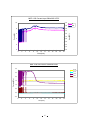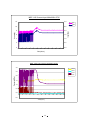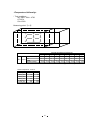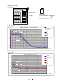
1
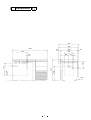
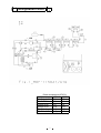
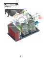
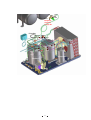
Service Manual
FILE No.
Ultra-Low Temperature Freezer
MDF-1156
MDF-1156ATN
SANYO Electric Co., Ltd.
Biomedical Business Unit
RoHS
This product does not contain any hazardous substances prohibited by the RoHS Directive.
(You will find ‘RSF’ mark near the rating plate on the RoHS compliant product.)
WARNING
* You are requested to use RoHS compliant parts for maintenance or repair.
* You are requested to use lead-free solder.
Effective models
This service manual is effective following models.
Model name
MDF-1156
Product code
823 188 54
MDF-1156ATN
823 188 83
823 188 84
Voltage and Frequency
230/240V
50Hz
220V
230/240V
60Hz
50Hz
Contents
㩷
Page
-----------------------------------------------------
1
---------------------------------------------------
2
-----------------------------------------------------
5
----------------------------------------------
6
-------------------------------------------
7
------------------------------------------------
8
-------------------------------------------
10
-----------------------------------------
11
--------------------------------------
12
Wiring diagram
-----------------------------------------
13
Circuit diagram
-----------------------------------------
14
Connections on PCB
-----------------------------------------
15
Control specifications
-----------------------------------------
16
Parts layout
---------------------------------------------------
23
Test data
---------------------------------------------------
26
----------------------------------------------
32
Features
specifications
Dimensions
Cooling unit parts
Refrigeration circuit
Welding points
Components on PCB
Electric specifications
Specifications of sensor
Instruction manual
㩷
Features
䂓㩷 Cooling performance
This chest type freezer has 128L for the capacity and the internal temperature maintains
-152㷄 or lower.
䂓㩷 New microprocessor temperature control has been used.
* Selectable warning system for high temperature alarm (15℃ or 10℃)
* Setting value (SV) can be kept by power failure alarm, remote alarm contact and
non-volatile memory.
* Alarm ring-back system installed.
䂓㩷 Environmental friendly
* HCFC free refrigerant R-407D is used in H stage side and HFC mixed refrigerant
in L stage side.
* CP urethane foaming for insulation (HCFC free)
䂓㩷 Optional component
* Aluminum container: MDF-49SC
1
Specifications
㩷
ŶStructural specifications
Item
MDF-1156
Name
MDF-1156AT
Ultra-Low Temperature Freezer
External dimensions
W1400 × D800 × H945 (mm)
Internal dimensions
W500 × D450 × H572 (mm)
Effective capacity
128 L
Exterior
Painted steel
Interior
Aluminum plate
Door
Painted steel
Insulation
Rigid polyurethane foamed-in place
Cooling circuit
Cooling performance
MDF-1156ATN
Secondary cooling circuit
Center of the chamber; -152㷄(AT;30㷄, no load䋩
Compressor
Hermetic type, 1100 x 2
Evaporator
Tube on sheet type
Condenser
Fin and tube type (high stage side)
Shell and tube type (low stage side)
Refrigerant
H stage side; R-407D
L stage side; HFC mixed refrigerant
Refrigerating oil
Ze-NIUS32SA
Power supply
Local voltage
Battery
For power failure alarm; Nickel-cadmium battery, 6VDC, 270mAh
For back-up system; Lead storage battery, 6VDC, 4Ah
Weight
Accessories
265 kg
272 kg
272 kg
1 set of key, 1 scraper, 2 rubber caps, 1 inner lid
1 connect tube for back-up system
6 recording chart rolls, 2 recording pens (cartridge)
Option
Aluminum container䋨MDF-49SC䋩
㩷
㩷
㩷
㩷
㩷
㩷
㩷
㩷
㩷
㩷
㩷
2
ŶControl specifications
Item
Cooling performance
MDF-1156
MDF-1156AT
MDF-1156ATN
Center of the chamber; -152㷄䋨AT30㷄, No load䋩
Temp. controller
Micro-processor control system
Setting range; -125㷄䌾-155㷄䋨Unit;1㷄䋩
Non-volatile memory
Temp. sensor
Pt.100ȍ
Temp. display
Digital (LED) display
Setting range: +15㷄 or +10㷄 (Initial: +15㷄)
ALARM lamp blinks and intermittent buzzer tone with 15min. delay
High temp.
Remote alarm contact: Normal Open, Rating: DC30V, 2A
Temperature alarm turns on during power failure.
(Not linked with buzzer)
Alarm resume function䋨OFF:0, 10䌾60: minute increment䋩
Alarm
Filter
Power failure
Remote alarm
Filter check lamp blinks and intermittent buzzer tone
ALARM lamp blinks and intermittent buzzer tone
Remote alarm contact turns over.
3P remote alarm terminal: DC30V, 2A, NC-COM, NO-COM
Temperature alarm turns on during power failure.
Lamp: ALARM䇮FILTER䇮BACKUP
Display: LED
Buzzer key: BUZZER
Control panel
Alarm test key: ALARM TEST
To switch SV and PV: SET
To shift the digit: 䋾
To change the digit: ȁ
Entry set key: ENT
Battery switch
Switches
Remote alarm contact ON/OFF switch
Back-up test switch
Back-up ON/OFF switch
In the event of any failure among temp. sensor, filter sensor and
Self diagnosis function
cascade sensor;
zError code and PV are alternately displayed.
zRemote alarm contact turns over and intermittent buzzer emit.
Battery switch
Toggle switch (250VAC, 4A)
When the temperature in cascade sensor is -24 㷄 or lower,
Compressor protection
compressor (L) turns on.
When is -10㷄 or higher, compressor (L) turns off.
Overload relay and compressor (H) are controlled.
3
㩷
ŶPerformance specifications
Cooling performance
Center of the chamber: -152㷄䋨AT30㷄, no load䋩
Temp. control range
-130㷄䌾-152㷄
Rated power consumption
220VAC, 50Hz
220VAC, 60Hz
230VAC, 50Hz
240VAC, 50Hz
1550W
1700W
1550W
1600W
Alarm duration
Noise level
9 hours
61 dB (A) (background noise; 20dB)
Maximum pressure
2844 kPa
Usable conditions
AT:5㷄䌾30㷄, less than 80䋦RH
Note: Specifications will be subject to change without notice.
㩷
4
Dimensions
958
905
1400
53
800
500
52
450
30
15
667
667
945
572
240
400
105
5
Cooling unit parts
MDF-1156/1156ATN㩷 㩷 㩷 㩷 㩷 㩷 㩷 㩷 㩷 㩷 㩷 㩷 㩷 㩷 㩷 㩷 㩷 㩷 㩷 㩷 㩷 㩷 㩷 㩷 㩷 㩷 㩷 㩷 㩷 㩷 㩷 㩷 㩷 㩷 㩷 㩷 㩷 㩷 㩷 㩷 㩷 㩷 㩷 㩷 Unit (mm)
Specifications
Parts name
H stage side
L stage side
220V/60Hz
220V/50Hz
230-240V/50Hz
220V/60Hz
220V/50Hz
230-240V/50Hz
Compressor
KS370J1NS-4A
KS370J1NS-4A1
Type KS370J1NS-7A KS370J1NS-4A KS370J1NS-4A1 KS370J1NS-7A
Rated voltage
Single
220/230V,
60Hz
Single,
220V, 60Hz
Single
230/240V,
50Hz
Single
220/230V,
60Hz
Single,
220V, 60Hz
Refrigerant oil
Cooling method
Condenser
Type
Ze-NIUS32SA charged q’ty 850cc
Partially forcible and oil cooler
Condenser
Pre-condenser
Frame pipe
Evaporator
Type
Capillary tube
12 lines 4columns, (P) 6.35, Fin 88pcs
-----
W 350(2 lines)
ij6.35
---------
Resistance
PSI・kg/cm
Fin and tube
56psi
1300
ij2.4
ij1.2
Length(mm)
Outer Diameter(mm)
Inner Diameter(mm)
Refrigerant
Dryer
Condensing fan
Condensing fan
motor
Type
Oil separator
Type
Ze-NIUS32SA charged q’ty 850cc
Partially forcible and oil cooler
(Cascade condenser)
Shell tube
ij6.35 x (T) 0.7
Shell tank, ij80
2
R-407D
Tube on sheet
(upper)
(middle)
(lower)
2
2
2
9.9 kg/cm
Charged q’ty: 470±5g
Oil additive: n-pentane 50cc(30g)
4AXH-9 Charged q’ty: 18g
ABS, 4 blades, ij230 x H85
11.0 kg/cm
1.9 kg/cm
8000
3000
500
1.8
1.8
2.0
1.8
2
MU-N711A(HFC mixed refrigerant)
Charged q’ty: 638g
4AXH-6
Charged q’ty: 58g
---------
SPK-0S02S3
6
3.7 kg/cm
(EX)
3000
FL2-021R5MP (for compressor cooling)
SE4-E11L5P Output: 10W
-----
Single
230/240V, 50Hz
Ze-NIUS32SA、500 ㏄
Refrigeration circuit
Reach temperature(AT30㷄)
50Hz
60Hz
㽲H EVA OUT
-32
-32
㽳HEAT EX1
-50
-52
㽴HEAT EX2
-70
-76
㽵HEAT EX3
-113
-117
㽶L EVA IN
-154
-157
㽷L EVA OUT
-148
-154
䋪Reference only
7
Welding points
㩷 䇼Unit Base Ass’y䇽
䌌䌂䌂
䌅䌘䌇
Ex tank L
䌌䌂䌃
䌅䌘䌆㩷
䌅䌘䌄
䌅䌘䌂
䌅䌘䌏
䌅䌘䌁
䌅䌘䌃
䌈䌆䌏
䌈䌆䌉㩷
䌌䌄䌄
䌔䋸㩷
䌅䌘䌅㩷
䌔䋴㩷
䌔䋹㩷
䌔䋷㩷
䌔䋶㩷
䌌䌃䌃㩷
Refrigerant
Charged in
L stage side
䌔䋱㩷
䌔䋵㩷
䌐䋲㩷
䌔䋲㩷
䌔䋳㩷
䌏䌉㩷
䌌䌄䌃㩷
䌏䌒㩷
䌏䌏㩷
Pressure SW
䌌䌄䌅㩷
䌐䋱㩷
䌈䌓䌆㩷
Condenser Ass’y
䌈䌓䌅㩷
Compressor L
䌈䌄䌇
䌌䌄䌂 䌍䌉㩷
䌌䌏䌁
䌈䌄䌃
䌌䌏䌂
䌌䌏䌉㩷
䌌䌄䌁
䌌䌏䌏
䌍䌏㩷
䌈䌄䌄
䌈䌄䌈
8
Compressor H
䌈䌏䌁㩷
䌈䌄䌂㩷䌈䌏䌂㩷
䌈䌓䌄 䌈䌄䌁㩷
䌈䌏䌉㩷
䌈䌏䌏㩷
䌈䌓䌃㩷
䌈䌄䌉㩷
䌈䌃䌆 䌈䌃䌄
䌈䌃䌃㩷
Refrigerant
charged in
H stage side
䌈䌃䌅
EX capillary
䌅䌘䌉㩷
䌓䌔䋳
䌓䌔䋲
䌓䌔䋱
䌈䌃䌁㩷
䌌䌄䌃㩷
䌈䌓䌇㩷
䌈䌃䌂㩷
䌌䌃䌂
䌌䌓䌃
䌈䌓䌁
䌌䌄䌅㩷
䌌䌓䌁 䌌䌓䌂
䌌䌃䌁
䌈䌓䌂
䌈䌃䌁㩷
Oil separator
Capillary H
䌈䌄䌉㩷
䌈䌄䌏㩷
䌈䌃䌏
9
Components on PCB
10
Electric specifications
MDF-1156/1156ATN
Compressor (H), (L)
Type
Code
Rated voltage
Winding resistance C-S(Aux)
C-R(Main)
ST relay (H), (L)
Type
Pick-up voltage
Drop-out voltage
Parts code
Overload relay (H), (L)
Type
Action to the temp. (no current)
Action to the current (AT25C)
Operation time
Parts code
Starting capacitor (H), (L)
Rating
Running capacitor (H), (L)
Rating
Condensing fan motor (F)
Type
Rating
Condensing fan motor (R)
Type
Rating
Cap.tube heater
Rating
Resistance䋨25㷄)
Parts code
Temp. control relay (H), (L)
Type
Contact capacity
Parts code
Pressure switch
Type
Rating
Breaker switch
Type
Rating
Power transformer
Type
Rating
Parts code
Battery switch
Type
Rating
Battery
Type
Rating
Temp. sensor
Type
A.T. sensor
Type
Rating
Cascade sensor
Type
Rating
Filter sensor
Type
Rating
Remote switch
Type
Rating
Solenoid valve
Type
(1156ATN only)
Rating
Back up switch
Type
(1156ATN only)
Rating
Test switch
Type
(1156ATN only)
Rating
11
220VAC, 60Hz
220VAC, 50Hz
230/240VAC, 50Hz
KS370J1NS-7A
7FB-0-M101-001-06
220V, 60Hz
1.64㱅
3.35ȍ
AMVL-300A
215~247V (60Hz)
69~132V (60Hz)
626 100 1503
MST16AG135/69
ON:135+/-5㷄 OFF:69+/-11㷄
29.5A
6~16sec
624 226 3173
250VAC, 160MF
400VAC, 25MF
FL2-C021R5MP
220-240VAC
SE4-E11L5P
220-240VAC
100V, 15.7W
638㱅
624 030 2492
G4F-11123T
20A, 12VDC
624 173 2397
SNS-C135Q002
OFF:2.75 ON:0.78
BAM215171
250V, 15A
ATR-C50
200-240V
624 173 2397
SLE6A2-5
250VAC, 4A
5N-270AA
6V, 270MAH
PT-100㱅
502AT
5K㱅, 25㷄
502AT
5K㱅, 25㷄
502AT
5K㱅, 25㷄
HLS112D
250VAC, 6A
8263205LT
24VDC, ORF:5.6
HLS208N
125V, 5A
8R1021-Z
125V, 3A
KS370J1NS-4A
7FB-0-M101-001-04
220/230V, 50Hz
2.53㱅
4.8ȍ
AMVL-300A
185~217V (50Hz)
60~120V (50Hz)
626 100 1503
MST16AJ135/69
ON:135+/-5㷄 OFF:69+/-11㷄
22.5A
6~16sec
624 226 3166
250VAC, 100MF
400VAC, 25MF
FL2-C021R5MP
220-240VAC
SE4-E11L5P
220-240VAC
100V, 15.7W
638㱅
624 030 2492
G4F-11123T
20A, 12VDC
624 173 2397
SNS-C135Q002
OFF:2.75 ON:0.78
BAM215171
250V, 15A
ATR-C50
200-240V
624 173 2397
SLE6A2-5
250VAC, 4A
5N-270AA
6V, 270MAH
PT-100㱅
502AT
5K㱅, 25㷄
502AT
5K㱅, 25㷄
502AT
5K㱅, 25㷄
HLS112D
250VAC, 6A
8263205LT
24VDC, ORF:5.6
HLS208N
125V, 5A
8R1021-Z
125V, 3A
KS370J1NS-4A1
7FB-0-M101-001-05
230/240V, 50Hz
2.53㱅
4.8ȍ
AMVL-300A
185~217V (50Hz)
60~120V (50Hz)
626 100 1503
MST16AJ135/69
ON:135+/-5㷄 OFF:69+/-11㷄
22.5A
6~16sec
624 226 3166
250VAC, 100MF
400VAC, 25MF
FL2-C021R5MP
220-240VAC
SE4-E11L5P
220-240VAC
100V, 15.7W
638㱅
624 030 2492
G4F-11123T
20A, 12VDC
624 173 2397
SNS-C135Q002
OFF:2.75 ON:0.78
BAM215171
250V, 15A
ATR-C50
200-240V
624 173 2397
SLE6A2-5
250VAC, 4A
5N-270AA
6V, 270MAH
PT-100㱅
502AT
5K㱅, 25㷄
502AT
5K㱅, 25㷄
502AT
5K㱅, 25㷄
HLS112D
250VAC, 6A
8263205LT
24VDC, ORF:5.6
HLS208N
125V, 5A
8R1021-Z
125V, 3A
Specifications of sensor
1. Following shows the temperature of temp. sensor (502AT) and its resistance value.
㷄
kȍ
㷄
kȍ
㷄
kȍ
㷄
kȍ
䋭50
154.5
䋭36
71.80
䋭22
35.65
0
13.29
䋭49
145.9
䋭35
68.15
䋭21
33.99
5
10.80
䋭48
137.8
䋭34
64.71
䋭20
32.43
10
8.84
䋭47
130.2
䋭33
61.48
䋭19
30.92
15
7.20
䋭46
123.1
䋭32
58.43
䋭18
29.50
20
6.01
䋭45
116.5
䋭31
55.55
䋭17
28.14
25
5.00
䋭44
110.2
䋭30
52.84
䋭16
26.87
30
4.17
䋭43
104.4
䋭29
50.23
䋭15
25.65
35
3.50
䋭42
98.87
䋭28
47.77
䋭14
24.51
40
2.96
䋭41
93.70
䋭27
45.45
䋭13
23.42
45
2.51
䋭40
88.85
䋭26
43.26
䋭12
22.39
50
2.13
䋭39
84.18
䋭25
41.19
䋭11
21.41
55
1.82
䋭38
79.80
䋭24
39.24
䋭10
20.48
60
1.56
䋭37
75.67
䋭23
37.39
䋭5
16.43
65
1.35
㩷
㩷
2. Following shows the temperature of temp. sensor (Pt100ȍ- NEW JIS) and its resistance
value.
㷄
ȍ
㷄
ȍ
㷄
ȍ
㷄
ȍ
䋭170
31.32
䋭100
60.25
-30
88.22
40
115.54
䋭160
35.79
䋭90
64.30
-20
92.16
50
119.40
䋭150
39.82
䋭80
68.33
-10
96.09
60
123.24
䋭140
43.87
䋭70
72.33
0
100.00
70
127.07
䋭130
48.00
䋭60
76.33
10
103.90
80
130.89
䋭120
52.11
䋭50
80.31
20
107.80
90
134.70
䋭110
56.19
䋭40
84.27
30
116.70
100
138.50
㩷
12
Wiring diagram
13
Circuit diagram
14
Connection on PCB
The following shows the connections of connectors on the control PCB.
Connector
Connects to
Usage
Voltage
#1-#2: 10.3VAC
To supply the power to PCB.
#3: GND
#4-#5: 18.5VAC
To supply the power during #1: 6VDC
#2: GND
power failure.
CN1
Power transformer
CN2
#1-#2: Battery
CN3
#1-#3: Temp. sensor
To detect internal temperature.
CN4
#1-#2: Cascade sensor
To
detect
cascade.
CN5
#1-#2: Filter sensor
To detect temperature in
condenser outlet pipe.
CN6
Remote switch
To output remote alarm
CN7
Display PCB
To connect to each LEDs.
CN8
#1-#2: Temp. control relay
To control internal temperature
CN9
#1: Cap. tube heater
#2: Power supply line
To supply the power to cap tube
heater.
CN10
#1: Temp. recorder
#3: Solenoid valve
CN11
Unused
CN12
Unused
CN13
Control PCB
temperature
To connect to each switches.
15
in
#1-#2: 12VDC
Control specification
1.
Key and Switch
BUZZER
:
In alarm condition, buzzer stops sounding with this key pressed.
Remote alarm output and alarm message would not be off.
ALARM
:
With this key pressed to activate alarm test mode to be forcibly step into
alarm condition (ALARM lamp blinks and intermittent buzzer sounds).
PV/SV
:
Press this key once to activate set mode (2nd digit in LED blinks), press the
key again to revert to current internal temperature (PV) display.
During set mode, shift between the 1st digit and the 2nd digit. In PV display,
press the key over 5 seconds to display filter sensor temperature for 3
seconds. (digit of decimal point is not displayed)
In PV display, press the key for 5 times in 5 seconds to turn capillary heater
on during the usual operation set time.
During set mode, count the blinking digit up. In PV display, press the key
over 5 seconds to enter the function mode. (“F00” is displayed)
In PV display, press the key for 5 times in 5 seconds to display the value of
decimal point for 3 seconds. (Ex. -80.3㷄 㸢 displays as 803)
ENTER
:
During set mode, press the key to store the displayed temperature as set
value (SV). In PV display, press the key for 5 times in 5 seconds to display
cascade sensor temperature for 3 seconds. (digit of decimal point is not
displayed)
2.
Temperature control
Setting range
: -125㷄䌾-155㷄
Display range
: -170㷄䌾+50㷄
Setting procedure : Press PV/SV key and set the required value with
key and
key.
Press ENTER key to memorize the set value.
Out of setting range : If you input the value out of setting range to press ENTER key, the input
value would not be entered with continuous buzzer beeps for 1 second.
Note) if you press PV/SV key instead of ENTER key, set value would not
be stored and automatically revert to PV display.
3.
High temperature alarm
Setting range
: Selectable 15㷄 or 10㷄 in F01 (High temp. alarm)
Setting procedure : Keep pressing
key over 5 seconds to enter function mode (F00).
Press again to count the value up. “F01” displayed to input the value of
high temperature alarm. (the 1st digit blinks)
(Ex. If you want to set at 10㷄 (initial 15㷄), change the value and press
ENTER key to store the value in non-volatile memory.
4.
Function mode
Setting range
Display range
: 00~31
: 00~39
00, 02, 04, 05, 08, 12~14, 18, 19, 23, 26~30 and 32~39 are not used.
Setting procedure :
In PV display, keep pressing
key over 5 seconds to enter function
mode (F00 is displayed). Change the blinking 1st digit to desired function
code with
key and
key. Press ENTER key to be function code
available.
If you input above unused function code and press ENTER key,
automatically revert to PV display.
16
Out of setting range :
5.
6.
7.
Warning function
High temp. alarm
:
Filter blockage
:
Other function
Cascade control
:
Auto return
:
If you input the value out of setting range and press ENTER key, the
input value would not be entered and automatically revert to PV display.
(applied function code: 32~39)
Note) If you press PV/SV key with any function mode (except F03, F09,
F10 and F15) displayed, the displayed value is ignored and automatically
reverts to PV display.
When PV is reached at SV+SVH (high temp. alarm SV) +1 or higher,
ALARM lamp and LED display blinks, intermittent buzzer beeps with
approx. 12 minutes of delay and remote alarm output turns on.
When PV is reached at SV+ SVH or lower, ALARM lamp and LED display
go off, buzzer stops beeping and remote alarm output turns off.
If you press BUZZER key, the buzzer stops beeping instead remote
alarm output does not turn off.
You can set SVH at selectable 15㷄 or 10㷄 in F01.
When the filter sensor temperature is reached at 45㷄 or higher, FILTER
lamp is lit. When the filter sensor temperature is reached at 41㷄 or
lower, FILTER lamp goes off.
Compressor (L) is allowed to turn on until the cascade sensor
temperature is reached at -24㷄 or lower during pull-down.
Compressor (L) is allowed to turn off until the cascade sensor
temperature is reached at -10㷄 or higher during pull-up.
If there is not any key operation for 90 seconds in SV set mode and
function code set mode, automatically reverts to PV mode.
Note) Auto return is not worked in F09 and F10.
Function mode
F00
Automatically revert to PV display
F01
SVH (high temp. alarm SV) setting
F02
Automatically revert to PV display
F03
Battery accumulation time display
F04~F05 Automatically revert to PV display
F06
Service code input (code: 384)
F07
Temperature Zero Adjustment
F08
Automatically revert to PV display
F09
(Factory test mode ………… Unused)
F10
(Factory test mode ………… Unused)
F11
(Cascade temperature Zero Adjustment ……… Unused)
F12~F14 Automatically revert to PV display
F15
AT sensor temperature display
F16
(Timer speed-up mode ……… Unused)
F17
Model code setting ……… Unused)
F18~F19 Automatically revert to PV display
F20
Capillary heater is forcibly turned off
F21
Communication ID setting
F22
Communication mode setting
F23
Automatically revert to PV display
F24
PV display (decimal point is displayed)
F25
Ring-back time setting, buzzer setting
F26~F30 Automatically revert to PV display
F31
Buzzer setting during filter alarm
F32~F39 Automatically revert to PV display
17
Setting procedure:
(1) In PV display, keep pressing
key over 5seconds to display “F00”.
(2) Input your desired function code with
key and
key.
(3) Press ENTER key to be function mode available.
Note) You should input service code in F06 prior to use F07, F15, F20, F21,
F22, F24 and F31.
To cancel service code, input “000” in F06 or turn the power off.
F00:
<Purpose> Simply passing through if entered by mistake.
<Operation> Press ENTER key in “F00” displayed to revert to PV display..
F01:
<Purpose> SVH (high temp. alarm SV) setting
<Operation> Input F01 and press ENTER key to display “001” (initial value).
Set selectable “000” or “001” with
key. Press ENTER key to
store the value and revert to PV display.
F02:
<Purpose> Simply passing through if entered by mistake.
<Operation> Press ENTER key in “F02” displayed to revert to PV display.
F03:
<Purpose> Battery accumulation time is displayed.
<Operation> Input F03 and press PV/SV key to display F03 and battery
accumulation time (XXX) alternately.
<Cancel> Press PV/SV key to revert to PV display.
F04~F05
<Purpose> Simply passing through if entered by mistake.
<Operation> Press ENTER key in “F04~F05” displayed to revert to PV display.
F06:
<Purpose> Dividing F-code for customer used from service
<Operation> Input F06 and press ENTER key to display “000” (initial value).
Set to “384” with
key and
key.
Press ENTER key to store the value and revert to PV display.
<Cancel> Input F06 and press ENTER key to display “384”.
Change to “000” with
key and
key. Press ENTER key to
store the value and revert to PV display.
Turn the power off then on to revert to “000”. (not stored in
non-volatile memory)
Note) “384” is storied in non-volatile memory during battery back-up.
(battery SW is ON)
F07:
<Purpose> To match controlled temperature of temp. sensor with 1/2H temp.
<Operation> Input F07 and press ENTER key to display “000” (initial value).
Change to the desired value (-99~099) with
key and
key.
Press ENTER key to store the value and revert to PV display.
Input service code in F06 prior to use this mode.
F08:
<Purpose> Simply passing through if entered by mistake.
<Operation> Press ENTER key in F08 displayed to revert to PV display.
F12~14:
F15:
F18~F19
<Purpose> Simply passing through if entered by mistake.
<Operation> Press ENTER key in F12~15 displayed to revert to PV display.
<Purpose> AT sensor temperature is displayed.
<Operation> Input F15 and press PV/SV key to display F15 and the current AT
sensor temperature (XXX) alternately.
Input service code in F06 prior to use this mode.
<Cancel> Press PV/SV key to revert to PV display.
<Purpose> Simply passing through if entered by mistake.
<Operation> Press ENTER key in F18~19 displayed to revert to PV display.
18
F20:
<Purpose> Capillary heater is forcibly turned off.
<Operation> In F20 displayed, press ENTER key to display “000”. (initial value)
Change the value to “001” with
key and press ENTER key to turn
capillary heater off continuously. Revert to PV display.
Input service code in F06 prior to use this mode.
F21:
<Purpose> Serial communication ID is set.
<Operation> Input F21 and press ENTER key to display “000” (initial value).
Change to your desired value in 001~255 with
key and
key.
Press ENTER key to store the value and revert to PV display.
Input service code in F06 prior to use this mode.
F22:
<Purpose> Serial communication mode is set.
<Operation> Input F21 and press ENTER key to display “000” (initial value).
Change to following alternative value with
key and
key.
Press ENTER key to store the value and revert to PV display.
Input service code in F06 prior to use this mode.
Control mode (the 3rd digit):
Baud rate (the 2nd digit):
0 (Local) … initial value
1 (Remote) … SV unchangeable
0 … 2400bps
1… 4800bps
2… 9600bps
F23:
<Purpose> Simply passing through if entered by mistake.
<Operation> Press ENTER key in F23 displayed to revert to PV display.
F24:
<Purpose> PV is displayed in 3 digits (digit of decimal point is displayed)
<Operation> In F24 displayed, press ENTER key to display “000” (initial value)
Change the value to “001” with
key and press ENTER key.
Ex.) -85.1㷄 㸢 851
Service code should be input in F06 prior to use this mode.
F25:
<Purpose> Alarm ring-back setting
<Operation> Input F25 and press ENTER key to display “130” (initial value).
Change the value with
key and
key.
Press ENTER key to store the value and revert to PV display.
The setting to turn both buzzer
press BUZZER key;
000: ring-back OFF
010: ring-back after 10min. later
020: ring-back after 20min. later
030: ring-back after 30min. later
and remote alarm relay off if you
040: ring-back after 40min. later
050: ring-back after 50min. later
060: ring-back after 60min. later
The setting to solely turn buzzer off if you press BUZZER key;
100: ring-back OFF
140: ring-back after 40min. later
110: ring-back after 10min. later 150: ring-back after 50min. later
120: ring-back after 20min. later 160: ring-back after 60min. later
130: ring-back after 30min. later (initial value)
F26~30:
F31:
<Purpose> Simply passing through if entered by mistake.
<Operation> Press ENTER key in F26~F30 displayed to revert to PV display.
<Purpose> Buzzer setting during filter alarm
<Operation> In F31 displayed, press ENTER key to display “000” (initial value).
Change to “001” with
key and press ENTER key to beep buzzer
during filter alarm. Service code should be input in F06 prior to use
this mode.
19
F32~39:
<Purpose> Simply passing through if entered by mistake.
<Operation> Press ENTER key in F32~F39 displayed to revert to PV display.
8.
Differential point (where the compressor is allowed to turn on and off )
ON:
SV +0.5㷄
OFF: SV -0.5㷄
9.
Temperature adjustment between temp. sensor and 1/2H
Adjustment (offset) is done by the software installed in the unit.
Unacceptable for manual change.
Offset value: +/- 0.0㷄
10.
Remote alarm
(1) High temp. alarm (RLY 1)
In normal condition:
Remote alarm contact is N.O. N.C.
㸣
㸣
In alarm condition:
Remote alarm contact is N.C. N.O.
(2) Power failure alarm (RLY 3)
In normal condition:
Remote alarm contact is N.O. N.C.
㸣
㸣
In power failure:
Remote alarm contact is N.C. N.O.
11.
Sensor failure
(1) Temp. sensor
Open circuit: E01 and 50㷄 are displayed alternately, the buzzer beeps intermittently
and remote alarm contact outputs.
The compressor is allowed to turn on.
Press BUZZER key to stop the buzzer beeping.
Short circuit: E02 and -170 㷄 are displayed alternately, the buzzer beeps
intermittently and remote alarm contact outputs.
The compressor is allowed to turn on.
Press BUZZER key to stop the buzzer beeping.
(2) Cascade sensor
Open circuit: E03 and PV are displayed alternately, the buzzer beeps intermittently
and remote alarm contact outputs.
At the time temperature in cascade sensor is detected at -24C or lower
(resistance value is 㺙㱅) that causes the compressor (L) is not forcibly
turned off. Press BUZZER key to stop the buzzer beeping.
Short circuit: E04 and PV are displayed alternately, the buzzer beeps intermittently
and remote alarm contact outputs.
Press BUZZER key to stop the buzzer beeping.
At the time temperature in cascade sensor is detected at -10C or higher
(resistance value is 0㱅) that causes the compressor (L) is forcibly turned
off.
(3) Filter sensor
Open circuit: E05 and PV are displayed alternately, the buzzer beeps intermittently
and remote alarm contact outputs.
Press BUZZER key to stop the buzzer beeping.
Short circuit: E06 and PV are displayed alternately, the buzzer beeps intermittently
and remote alarm contact outputs.
Press BUZZER key to stop the buzzer beeping.
20
(4) Error code priority
No.1:
No.2:
No.3:
No.4:
No.5:
Temp. sensor failure (E01 or E02)
Cascade sensor failure (E03 or E04)
Filter sensor failure (E05 or E06)
AT sensor failure (E07 or E08)
Condenser abnormal high temperature (E10)
(5) Temperature to judge failure
PT sensor:
50.0㷄 or higher with E01 displayed (open circuit)
-170㷄 or lower with E02 displayed (short circuit)
Cascade sensor: -64㷄 or lower with E03 displayed (open circuit)
70㷄 or higher with E04 displayed (short circuit)
Filter sensor:
-50㷄 or lower with E07 displayed (open circuit)
70㷄 or higher with E08 displayed (short circuit)
AT sensor:
60㷄 or higher with E10 displayed
E10 cancel: F sensor temp. </= AT sensor+10㷄
12.
Capillary heater turning on period
Cycle:
Every 12 hours
Turning-on time: 12 minutes
Timing:
Capillary heater should be turned on with regardless of the condition
of compressor (L). At the time compressor (L) should be OFF.
13.
When the power is supplied (without battery)
Compressor (H): Turns on with regardless of PV.
When the temperature in filter sensor is reached 60㷄 or higher,
compressor (H) is forcibly turned off.
Compressor (L): In PV䋾SV+0.5㷄 (when the cascade sensor temperature is -24㷄 or
lower), compressor (L) turns on with 2minutes (initial value) of delay
after the power was supplied.
Setting data:
The setting data initialized in F17 is retrieved in non-volatile memory.
14.
Lamp and buzzer
(1) Control PCB
DP1: Green lamp
Goes off: Compressor (L) turns off. (normal condition)
Lit
: Compressor (L) turns on.
DP2: Red lamp
Goes off: Cap. tube heater turns off. (normal condition)
Lit
: Cap. tube heater turns on.
DP3: Yellow lamp
Lit
: Compressor (H) turns on. (normal condition)
Goes off: Compressor (H) turns off.
(2) Display PCB
DP102: Red lamp
Goes off: Not in alarm condition (normal condition)
Blinks : High temp. alarm (without delay), or sensor failure, or power
failure
DP101: Red lamp
Goes off: Not in filter alarm
Lit
: In filter alarm
21
DP103: Green lamp
Goes off: Back-up switch OFF (normal condition)
Lit
: Back-up switch ON
(3) Buzzer
High temp. alarm:
Sensor failure:
Power failure:
Key quick:
Out of input range:
Intermittent tone with 12minutes of delay
Intermittent tone when EXX (XX=01~08) is displayed
Intermittent tone
Short tone if key quick is available
1 second continuous tone
22
Parts layout
Catch the picks to pull the panel out of
䋼Back of the display panel䋾
Display PCB
Control PCB
MDF-1156AT
䋼Under the control panel䋾
Open the side panel to replace Control PCB.
䊐䉞䊦䉺䉶䊮䉰
㪝㫀㫃㫋㪼㫉
MTR-155H
䇭
㪘㪻㫁㫌㫊㫋㫄㪼㫅㫋㩷㫊㪺㫉㪼㫎㩷㪽㫆㫉㩷㫋㪿㪼㩷㫇㪼㫅
㶎 Turn the screw to the direction of arrow
Control panel
Lock for control panel
to set the temperature lower and arrow
to set the temperature higher.
23
Battery for back-up
Solenoid valve
Service valve (H)
䋼Right side view䋾
Pressure switch
Compressor (H)
Compressor (L)
<Behind compressor (L)>
Oil separator
24
䋼Lower area - Back䋾
Remote alarm
To sensor (PT100ȍ)
Condensing fan motor R
To Temp. recorder
Remote alarm
12P terminal
䋼Electric BOX䋾
3P terminal
Temp. control
relay L
Temp. control
relay H
Starting relay L
Starting relay H
Starting capacitor L
Runninng capacitor L
Running capacitor H
Starting capacitor H
䋼Main PCB䋾
Power
transformer
Sensor (PT100ȍ)
Battery
25
Test data
㪥㫆㫋㪼㪀 㪝㫆㫃㫃㫆㫎㫀㫅㪾㩷㪻㪸㫋㪸㩷㪸㫉㪼㩷㫋㪿㪼㩷㫉㪼㪽㪼㫉㪼㫅㪺㪼㩷㫆㫅㫃㫐㪅
MDF-1156 H/L Temperature in pull doun (50Hz230V AT30)
60
H EVA OUT
40
HEAT Ex1
20
HEAT Ex2
0
HEAT Ex3
Temperature(㷄䋩
-20
L EVA IN
-40
L EVA OUT
-60
1/2h Air
-80
AT
-100
-120
-140
-160
㪇
㪉
㪋
㪍
㪏 㪈㪇 㪈㪉 㪈㪋 㪈㪍 㪈㪏 㪉㪇 㪉㪉 㪉㪋
Time(hour)
MDF-1156 Temperature in pull up (AT30)
㪇
㪄㪉㪇
Temperature(㷄䋩
㪄㪋㪇
㪄㪍㪇
㪄㪏㪇
1/2h Air
㪄㪈㪇㪇
㪄㪈㪉㪇
㪄㪈㪋㪇
㪄㪈㪍㪇
㪇
㪈
㪉
㪊
㪋
㪌
Time(hour)
26
㪍
㪎
㪏
㪐
MDF-1156 Current-Input 50Hz230V AT35
2.0
10
A
Kw
1.8
8
1.6
6
1.2
1.0
4
0.8
Input(KW)
Current(A)
1.4
0.6
2
0.4
0.2
0
0.0
0
2
4
6
8
10
12
14
16
18
20
22
24
Time(hour)
MDF-1156 Unit Pressure 50Hz230V AT35
3.0
H Pd
H Ps
2.5
L Pd
L Ps
Pressure(MPa)
2.0
1.5
1.0
0.5
0.0
-0.5
㪇
㪉
㪋
㪍
㪏
㪈㪇
㪈㪉
㪈㪋
Time(hour)
27
㪈㪍
㪈㪏
㪉㪇
㪉㪉
㪉㪋
12
3.0
10
2.5
8
2.0
6
1.5
4
1.0
2
0.5
0
A
Kw
Input(Kw)
Current(A)
MDF-1156 Current-Input 60Hz220V AT35
0.0
0
2
4
6
8
10
12
14
16
18
20
22
24
Time(hour)
MDF-1156 Unit Pressure 60Hz220V AT35
3.0
H Pd
H Ps
2.5
L Pd
Pressure(MPa)
L Ps
2.0
1.5
1.0
0.5
0.0
0
2
4
6
8
10
12
14
-0.5
Time(hour)
28
16
18
20
22
24
<Temperature Uniformity>
* Test conditions:
ĭ1, 50Hz䇭230䌖䇭AT30
AT=30㷄
SV=-150㷄
Measuring point: 㽲䌾㽺
㽲
㽵
㽸
㽳
㽶
㽹
㽴
㽷
㽺
Internal temperature (reference)
SV
MAX
MIN
-150㷄
AVRG
Variation (±3deg)
①
②
③
④
-147.3 -148.6 -149.0 -146.0
-150.2 -150.9 -151.3 -149.8
-148.8 -149.7 -150.1 -148.3
±1.4
±1.2
±1.2
±1.9
⑤(*) ⑥
⑦
⑧
⑨
-148.7 -148.8 -146.8 -148.2 -148.6
-150.9 -151.2 -149.8 -150.5 -151.1
-149.8 -150.0 -148.4 -149.3 -149.8
±1.1
±1.2
±1.5
±1.2
±1.3
(*) … 1/2H temperature
Reach temperature - AT30㷄
50Hz230V 60Hz220V
H EVA_out
-32
-32
HEAT_Ex1
-50
-52
HEAT_Ex2
-70
-76
HEAT_Ex3
-113
-117
L EVA_in
-154
-157
L EVA_out
-148
-154
29
<Sample load test>
1. Load layout
Sensor BOX
Conditions:
Load: 500ml water x 20bottles
(10L)
Water temp: approx. 30㷄
2" BOX
2. SV: -155㷄
1/2H
ᐶౝ㪈㪆㪉㪿
Sample load test㵘㵘䋨Load: 10L water䋩
Temp.䋨㷄䋩
Temp.sensor
᷷⺞䍜䍻䍙
㪋㪇
Ԛ
㪉㪇
1/2H
H
EVA
䌈䍒䍨䍼䍏䍑䍢
ԙ
㽲
ԛ
㪇
㽳
H EVA
Ԙ
㽴
㪄㪉㪇
㽵
㪄㪋㪇
㪄㪍㪇
Temp.sensor
㪄㪏㪇
㪄㪈㪇㪇
㪄㪈㪉㪇
㪄㪈㪋㪇
㪄㪈㪍㪇
㪇
㪍
㪈㪉
㪈㪏
㪉㪋
㪊㪇
㪊㪍
㪋㪉
㪋㪏
Time䋨䌨䋩
3. SV:-150㷄
㪫㪼㫄㫇㪅䋨㷄䋩
Sample load test㵘SV-150㷄
㪄㪈㪊㪇
ᐶౝ㪈㪆㪉㪟
1/2H
᷷⺞䍜䍻䍙
Temp.sensor
㪄㪈㪊㪌
㽲
㪄㪈㪋㪇
Temp.sensor
㪄㪈㪋㪌
1/2H
㽳
㽴
Ԛ
㪄㪈㪌㪇
㪄㪈㪌㪌
Ԙ
ԙ
㪄㪈㪍㪇
㪇
㪈
㪉
㪊
㪋
㪌
30
㪍
㪎
㪏
㪫㫀㫄㪼䋨㪿䋩
㪋㪅㩷SV:-130㷄
Temp.䋨㷄䋩
ᐶౝ㪈㪆㪉㪟
1/2H
Sample load test㵘SV-130㷄
㪄㪈㪉㪇
Temp.sensor
᷷⺞䍜䍻䍙
Temp.sensor
㽲
㪄㪈㪉㪌
㽳
㽴
㪄㪈㪊㪇
Ԛ
㪄㪈㪊㪌
1/2H
㪄㪈㪋㪇
ԙ
Ԙ
㪄㪈㪋㪌
㪄㪈㪌㪇
㪇
㪈
㪉
5. Temperatures in each SV
㪧㫆㫀㫅㫋㩷㽲 㪧㫆㫀㫅㫋㩷㽳
SV-155㷄 -154.3
-154.9
SV-150㷄 -151.9
-152.6
SV-130㷄 -132.0
-132.3
㪊
㪧㫆㫀㫅㫋㩷㽴
-153.3
-150.8
-131.0
㪋
㪌
㪧㫆㫀㫅㫋㩷㽵
-152.7
-150.2
-130.5
6. Condition: No load
Time needs to reach -150㷄
Lowest reach temp(㷄)
㵘㵘
1/2H
㵘㵘㵘㵘㵘㵘㵘㵘㵘
50cm above the bot
㵘㵘㵘㵘㵘㵘㵘㵘㵘㵘㵘㵘
50cm under the
Display
Temp. characteristics
㵘㵘㵘㵘㵘SV-150㷄
SV-130㷄
Running current (A)
Temp. changes during defrost
Time needs to defrost
31
㪍
1/2Air
-154.5
-152.2
-132.0
㪎
㪏
Time䋨䌨䋩
Unit(㷄)
Operaion ratio(%)
100
89
67
7hours 50min
-154.3
-154.6
-141
-153
-151.0
-131.5
5.3/5.5A
-152㵘㸢㵘-137
Approx. 15min