1
Climate Control Simplex
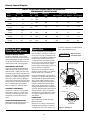
TABLE 1: AS-XXX SERIES POWEREX SIMPLEX AIR COMPRESSORS
PERFORMANCE SPECIFICATIONS
Base
Model
Actual Hp
1Ø
3Ø
Motor Rating
Hp
RPM
AS-105
.54
—
AS-005
—
.54
—
AS-107
.73
—
AS-007
—
.73
AS-110
1.07
—
—
AS-010
—
1.07
1.07
AS-015
—
1.54
AS-020
—
2.0
AS-030
—
AS-050
—
AS-075
—
AS-100
—
Compressor
RPM
1725
Compressor Capacity ACFM*
100% Runtime 50% Runtime 33% Runtime
800
1.8
0.9
0.6
1725
1040
2.5
1.25
0.83
1725
625
3.8
1.9
1.25
1.54
1750
955
6.4
3.2
2.11
2.0
1750
800
8.6
4.3
2.84
3.1
3.1
1745
775
12.0
6.0
4.0
5.6
5.6
1745
690
22.0
11.0
7.33
8.2
8.2
1745
795
28.5
14.3
10.3
10.3
1750
685
43.0
21.5
.54
—
.73
Mounted and
Connected Options
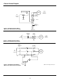
MAGNETIC MOTOR STARTER
An optional magnetic motor starter
which has been selected and wired for
the intended input voltage is available
for all units. All starters are furnished
with properly sized overload heaters.
REFRIGERATED AIR DRYER
A factory mounted Model Hankinson
HPR 5-10 Series refrigerated air dryer
with automatic condensate drain trap
assembly, bypass valve is available as an
option on all 1/2 through 3 Hp Powerex
Simplex air compressors. Piping for air
dryer is done at the factory. Wiring to
power source must be done in the field
using integral cord and plug which fits
into a standard 120 volt receptacle.
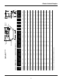
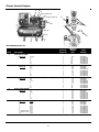
Refer to Table 2 for ordering details.
AUTOMATIC TANK DRAIN
Powerex air compressors are ordered
with either a manual or electric type
automatic tank drain. This unit is furnished with a manual drain attachment.
VIBRATION DAMPENING PADS
Waffle type design vibration pads are
provided as standard equipment.
1720
9.44
14.2
to release trapped air. Use Mobil Rarus
427® or Mobil DTE heavy oils.
Operation
Factory calibrated snap-acting DPST
pressure electric switches provide automatic cut-in and cut-out. Overpressure
protection is provided by an ASME safety relief valve. Receiver tanks have a
condensate drain valve with an extension for easy access. All mounting bases
are slotted for V-belt tension adjustment to aid in maintaining proper compressor and motor alignment.
! WARNING
Dispose of oil in
accordance with
state or local codes.
Remove cap and use
funnel to add oil.
All units are run through the factory
break-in and are tested for air delivery,
leakage and power consumption.
Units are shipped with a proper fill of
compressor oil in the crankcase and are
furnished with an intake filter/silencer
with a replaceable cartridge. This filter/silencer combination is designed to
remove contaminates in the inlet air
and provide quieter operation. The 5
through 10 Hp models are complimented by this design utilizing dual element
filtration which consists of a pleated
element and a foam element for filtration against larger particles from the
atmosphere.
Oil drain
cap
Oil gauge
Round (red)
Full
LUBRICATION
Check lubricating oil level at gauge.
Refill if necessary.
Change oil according to maintenance
schedule. Before draining oil, remove
oil supply cap and loosen oil drain cap
2
Low
OIL GAUGE
Figure 2 - Lubrication