1
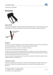
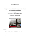
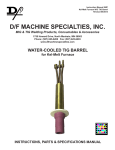
Modular
MULTIPLE
DISC BRAKE
(SAE D size)
Service Manual
This document is intended to provide general information about MICO Products. MICO, Inc. has attempted to present accurate information about MICO Products in its catalogs, brochures,
and other printed materials. MICO, Inc. is not responsible for errors, inaccuracies, or inconsistencies that may exist in any catalog brochure or other printed materials or any damages arising
from or related to reliance on information in them. Materials and specifications for MICO Products set forth in catalogs, brochures, and other printed materials are subject to change without
notice or obligation. Refer to www.mico.com for the most recent versions of our literature. If you have any questions concerning MICO Products, please contact MICO, Inc. All MICO Products
and service are sold and provided subject to the MICO Warranty at www.mico.com in effect on the date of sale or supply.
MICO is a trademark and registered trademark of MICO, Inc. MICO is registered in the U.S. Patent and Trademark Office as well as in Australia, Canada, Indonesia, Japan, Peoples Republic of China, South Korea, and the European Community.
MICO, Incorporated
Innovative Braking and Controls Worldwide
Form No. 81-550-005
1911 Lee Boulevard / North Mankato, MN U.S.A. 56003-2507
Tel: +1 507 625 6426 Fax: +1 507 625 3212
1990-01-01
www.mico.com
TYPICAL BRAKE
FIGURE 1
MICO, Inc.
(2)
Form No. 81-550-005
1990-01-01
PRINCIPLES OF OPERATION
These brakes are spring-set,
hydraulically released, multi-disc
brakes. They are used primarily for
holding loads, vehicles, conveyors,
etc. in place when the hydraulic
drive system is shut down or fails.
Although the brakes are rated at
3000 PSI, they only require from
100 PSI to 390 PSI to make them
function normally. The exact pressure required for operation is
dependent upon the number of
springs used to generate the torque
necessary to hold the designed
load. Thus, a brake with a full compliment of springs, will generate the
highest level of torque and require
approximately 390 PSI to fully
release the brake and provide
adequate running clearance for the
individual discs. A brake with 1/2 of
the full spring compliment will have
1/2 as much torque and will require
only 200 PSI to fully release the
brake. Consult catalog to choose
the torque which best suits your
design parameters.
It is very important to remember
that any pressure on the brake’s
release piston will directly effect the
level of torque.
Two application examples:
1. The brake has a release pressure of 200 PSI. The actuation
pressure is provided by a
charge pump. During certain
phases of the machines operation, the charge pump pressure
dips from 200 PSI to 100 PSI.
At 200 PSI, the brake runs free
(zero torque) but at 100 PSI
the brake will generate slightly
less than half of its rated
torque. The brake will drag failure may occur. In this case,
a brake should be selected
which has a lower release
pressure.
2. A brake has a release pressure
of 200 PSI. The system is set
up to hold a load when a variable pump is shifted into neutral. Everything is running fine
until the filter clogs, causing a
build-up of back pressure in the
return line to the tank. At a
pressure of 60 PSI, the brake
will lose 25% of its holding
torque; thus the load may slip.
The situation can be corrected
by replacing the filter or adding
an extra margin of safety to
your required brake torque in
the initial design.
These brakes are designed to give
thousands of trouble-free hours of
service when set up correctly in the
hydraulic circuit.
DESCRIPTION OF MODEL NUMBERS
OPTIONS
(Available separately
or in combination)
D - Double Bearing
S - Speed Sensor
Z - Oil Cooled*
OUTPUT FACE
D - SAE D-Mount
4-Bolt
OUTPUT SPLINE
13 - 13T 8/16
21 - 21T 16/32
17 - 17T 12/24
INPUT FACE
D - SAE D-Mount
C - SAE C-Mount
R - Closed Face
E - SAE E-Mount
INPUT SPLINE
13 - 13T 8/16
21 - 21T 16/32
17 - 17T 12/24
14 - 14T 12/24
00 - Used with R
Input Face only
TORQUE
*NOTE:
Form No. 81-550-005
1990-01-01
On oil cooled models
(Z - option) actual
torque is 67% of value
shown on torque code
chart.
(3)
1PSI = 0.06895 bar
Initial
Full
Code Torque Release Release
(lb�In) Pressure Pressure
(PSI)
(PSI)
20
20,000
250
390
16
16,000
200
300
13
13,000
160
250
12
12,000
150
240
10
10,000
130
190
90
9000
120
180
80
8000
100
150
55
5500
80
120
MICO, Inc.
DISASSEMBLY
1. Remove four socket head assembly bolts (21). A suitable
holding fixture is useful to keep
brake in position.
2. Tap female end of spline shaft
assembly (7) and spring plate
(13) with soft mallet to separate
cover. If sections will not separate, use a screwdriver to carefully pry sections apart.
3. Remove case gasket (6) from
cover plate (5).
4. Remove retaining ring (1) from
spline shaft assembly (7).
5. Remove spline shaft assembly
(7) from cover plate (5) by tapping male end of spline shaft
assembly with soft mallet.
6. Remove retaining ring (2) from
cover plate (5) and press out
oil seal (4) and bearing (3) if required.
7. Remove four socket head
shoulder bolts (9). A suitable
holding fixture is useful to hold
brake in position.
Do not remove shoulder bolts
without pressurization of brake
(approx. 400 PSI) or damage
may result.
8. Remove primary disc (10), six
thin rotor discs (11), two thick
rotor discs (22) and seven
stator discs (12).
9. Release the pressure to brake
before removing four socket
head cap screws (8).
10. Remove spring plate (13).
11. Remove case gasket (6) from
spring plate (13).
12. Before removing springs (14),
not pattern and color for reassembly purposes.
13. Remove piston (15) by carefully exerting hydraulic pressure to the release port in the
pressure plate (20).
14. Remove outside and inside
o-rings (17 & 19) and outside
and inside back-up rings (16 &
18) from piston (15).
Care must be taken so as not to
scratch or mar piston.
MICO, Inc.
ASSEMBLY
LUBRICATE ALL RUBBER COMPONENTS FROM REPAIR KIT
WITH CLEAN TYPE FLUID USED
IN TYPE SYSTEM.
1. Clean all parts thoroughly before assembling.
2. Press oil seal (4) into cover
plate bore (5) until it is flush
with bearing shoulder.
DRY DESIGN BRAKE; oil
seal (4) must be installed
with open side facing pilot
end of cover (5).
LIQUID COOLED BRAKE;
oil seal (4) must be in
stalled with closed side
facing pilot end of cover
(5).
3. Press bearing (3) into position
until it bottoms out on oil seal
borestep.
4. Install retaining ring (2) into
cover plate (5).
5. Press spline shaft assembly (7)
into bearing (3) until shaft bottoms on shaft shoulder. Bearings inner race must be
supported during this operation.
6. Install back-up rings (16 & 18)
on piston (15) toward spring
pockets.
7. Install o-rings (17 & 19) on
piston (15). Be sure o-rings are
flat and all twists removed.
to hold brake in position.
12. Install stator discs (12) and
rotor discs (11 & 22). Begin
with a thick rotor disc (22) and
alternate with stator discs (12)
and thin rotor discs (11). Complete with thick rotor disc (22).
13. Install primary disc (10).
14. Align discs and partially screw
in four socket head shoulder
bolts (9). SEE NOTE BELOW.
Inspect for free movement of
stack. Pressurize brake release
port (approx. 400 PSI) to release discs. Torque shoulder
bolts to 15 ft·lb and release
pressure. A suitable holding fixture is useful to hold brake in
position.
15. Install cover plate (5) using four
socket head assembly bolts
(21). SEE NOT BLOW. Torque
cap screws to 55 ft·lb.
NOTE
Bolts should have one or two drops
of Henkel Omnifit #1550 or Loctite
#609 applied to threads.
Care must be taken so as not to
scratch or mar piston.
8. Lubricate piston (15) with clean
type fluid used in the system.
Carefully press piston into
pressure plate (20). Be sure
piston is aligned correctly at all
times and that there are no
extrusions. Press piston until it
bottoms on pressure plate (20).
9. Install same number of springs
(14) according to pattern and
color as were removed during
disassembly. Different colored
springs must be alternated.
10. Affix self-adhesive case gaskets (6) to cover plate (5) and
spring plate (13).
11. Place unit on a press. Using a
fixture, depress and install four
socket head cap screws (8).
SEE NOTE BELOW. Torque
cap screws to 55 ft·lb. A
suitable holding fixture is useful
(4)
Form No. 81-550-005
1990-01-01
FOR REPAIR KIT INFORMATION REFER TO PAGE 7.
FIGURE 2
ITEM
1
2
3
4
5
6
7
8
9
10
DESCRIPTION
ITEM
11
12
13
14
15
16
17
18
19
20
21
22
RETAINING RING
RETAINING RING
BEARING
OIL SEAL
COVER PLATE
CASE GASKETS
SPLINE SHAFT ASSEMBLY
SOCKET HEAD CAP SCREWS
(ASSEMBLY BOLTS)
SOCKET HEAD SHOULDER BOLTS
(TENSION PINS)
PRIMARY DISC
Form No. 81-550-005
1990-01-01
(5)
DESCRIPTION
ROTOR DISCS
STATOR DISCS
SPRING PLATE
SPRINGS
PISTON
BACK-UP RING
O-RING
BACK-UP RING
O-RING
PRESSURE PLATE
SOCKET HEAD ASSEMBLY BOLTS
ROTOR DISC (THICK)
MICO, Inc.
BLEEDING
1. Install brake in system and
connect pressure lines.
2. Bleed pressure release section
of brake by pressurizing side
inlet port and allowing air to
escape from top port. Pressure
should not exceed 100 PSI
during bleeding.
3. Apply sufficient pressure to
release brake and check for
proper operation in system.
SERVICE DIAGNOSIS
PROBLEM
Brake slips
Brake drags or
runs hot
Brake will not
release
MICO, Inc.
CAUSE
EXPLANATION
ACTION
A. Excessive pressure in
hydraulic system
If there is back pressure in the actuation line of the brake, holding torque
will be reduced.
Check filters, hose size,
restrictions in other
hydraulic components.
B. Oil in brake if designed
for dry use
Wet linings generate 67% of the dry
torque rating. If the brake has oil in it,
check the type of oil hydraulic or gear
box.
1. Gearbox oil
2. Hydraulic oil
Replace oil seal in brake
Check motor seal
Check piston seals
Note: Internal components will need to be
inspected, cleaned and
replaced as required.
C. Disc plates worn
The thickness of the disc stack sets
the torque level. A thin stack reduces
torque.
Check disc thickness
D. Springs broken or have
taken a permanent set
Broken or set springs can cause reduced torque - a rare occurrence.
Check release pressure
(See spring replacement)
A. Low actuation pressure
The brake should be pressurized to
minimum of 20 PSI over the full release pressure under normal operating conditions. Lower pressures will
cause the brake to drag thus generating heat.
Place pressure gauge in
bleed port & check
pressure with system on
B. Bearing failure
If the bearing should fail, a large
amount of drag can be generated.
Replace bearing
C. Oil in brake
Excess fill of oil in sump condition
thru wet brakes can cause the unit to
run hot. Also excessive rpm in sump
condition.
Drain oil and refill as
specified for brakes or
Switch to flow thru
cooling.
A. Stuck or clogged valve
Brakes are designed to come on
when system pressure drops below
stated release pressure. If pressure
cannot get to brake, the brake will not
release.
Place pressure gauge
in bleed port - check
for adequate pressure Replace defective line or
component
B. Bad o-rings
If release piston will not hold pressure, brake will not release.
Replace o-rings
C. Discs frozen
These brakes are designed for only
limited dynamic braking. A severe
emergency stop or prolonged reduced
release pressure operation my result
in this type of damage.
Replace disc stack
(6)
Form No. 81-550-005
1990-01-01
REPAIR KITS
Form No. 81-550-005
NUMBER
DESCRIPTION
12-504-116
O-ring and Back-up
Ring Kit
Case Gaskets (6)
Oil Seal (4)
Back-up Rings (16 & 18)
O-rings (17 & 19)
Loctite
12-501-118
Lining Kit
Case Gaskets (6)
Primary Disc (10)
Stator Discs (12)
Rotor Discs (11 & 22)
Loctite
12-501-122
Bearing Kit
Case Gaskets (6)
Bearing (3)
Oil Seal (4)
Loctite
12-501-128
Spring Kit
Case Gaskets (6)
Springs (14)
Loctite
1990-01-01
(7)
INCLUDES
MICO, Inc.