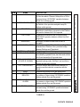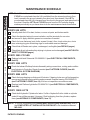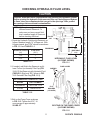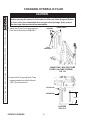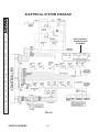
1
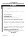
MAINTENANCE MANUAL
FOR
WHEELCHAIR LIFT
MODEL NO. WL7
DOT-Public Use Lift
PATENTS PENDING
© MAXON Lift Corp. 2005
MP-04-03
REV. C
SEPTEMBER 2005
PATENTS PENDING
11921 Slauson Ave.
Santa Fe Springs, CA. 90670
LIFT CORP.
CUSTOMER SERVICE:
TELEPHONE (562) 464-0099 TOLL FREE (800) 227-4116
FAX: (888) 771-7713
NOTE: For latest version of all Manuals (and replacements), download the
Manuals from Maxon’s website at www.maxonlift.com.
WARRANTY/ RMA POLICY & PROCEDURE
LIFT WARRANTY
Type of Warranty:
Full Parts and Labor
Term of Warranty:
6 years from ship date or 6,000 lifts
This warranty shall not apply unless the product is installed, operated and maintained in accordance with MAXON Lift’s specifications as set forth
in MAXON Lift’s Installation, Operation and Maintenance manuals. This warranty does not cover normal maintenance or adjustments, damage or
malfunction caused by improper handling, installation, abuse, misuse, negligence, or carelessness of operation. In addition, this warranty does
not cover equipment that has had unauthorized modifications or alterations made to the product.
MAXON agrees to replace any components which are found to be defective during the first 6 years of service, or 6,000 cycles whichever occurs
first, and will reimburse for labor based on MAXON’s Mobility Warranty Flat Rate Schedule.
All warranty repairs must be performed by an authorized MAXON Mobility warranty facility. For any repairs that may exceed $500, including
parts and labor, MAXON’s Technical Service Department must be notified and an “Authorization Number” obtained.
All claims for warranty must be received within 30 Days of the repair date, and include the following information:
1. Wheelchair Lift Model Number and Serial Number
2. Number of “LIFTS” displayed on the Lift Controller
3. End User information, name and phone number
4. Detailed Description of Problem
5. Corrective Action Taken, and Date of Repair
6. Parts used for Repair, Including MAXON Part Number(s)
7. MAXON R.M.A. # and/or Authorization # if applicable (see below)
8. Person contacted at MAXON, if applicable
9. Claim must show detailed information I.e. Labor rate and hours of work performed
Warranty claims can also be placed on-line at www.maxonlift.com. On-line claims will be given priority processing.
All claims for warranty will be denied if paperwork has not been received or claim submitted via Maxon website for processing by MAXON’s
Warranty Department within 30 days of repair date.
All components may be subject to return for inspection, prior to the claim being processed. MAXON products may not be returned without prior
written approval from MAXON’s Technical Service Department. Returns must be accompanied by a copy of the original invoice and are subject
to a credit deduction to cover handling charges and any necessary reconditioning costs. Unauthorized returns will be refused and become
the responsibility of the returnee.
Any goods being returned to MAXON Lift must be pre-approved for return, and have the R.M.A. number written on the outside of the package in
plain view, and returned freight prepaid. All returns are subject to a 15% handling charge if not accompanied by a detailed packing list.
Defective Parts requested for return must be returned within 30 days of the claim date for consideration to:
MAXON Lift Corp.
16205 Distribution Way, Cerritos, CA 90703
Attn: RMA#__
MAXON’s warranty policy does not include the reimbursement for travel time, towing, vehicle rental, service calls, oil, batteries or loss of income
due to downtime. Fabrication or use of non Maxon parts, which are available from MAXON, is also not covered.
MAXON Mobility’s Flat Rate Labor Schedule takes into consideration the time required for diagnosis of a problem.
All Lifts returned are subject to inspection and a 15% restocking fee. Any returned Lifts or components that have been installed or not returned
in new condition will be subject to an additional reworking charge which will be based upon the labor and material cost required to return the Lift or
component to new condition.
PURCHASE PART WARRANTY
Term of Warranty: 1 Year from Date of Purchase.
Type of Warranty: Part replacement only
MAXON will guarantee all returned genuine MAXON replacement parts upon receipt and inspection of parts and original invoice.
All warranty replacements parts will be sent out via ground freight. If a Rush Shipment is requested all freight charges will be billed to the
requesting party.
TABLE OF CONTENTS
SAFETY SUMMARY ............................................................................................................ 6
LIFT COMPONENTS & TERMINOLOGY ............................................................................... 8
MAINTENANCE SCHEDULE ........................................................................................... 10
CHECKING HYDRAULIC FLUID LEVEL............................................................................. 11
CHANGING HYDRAULIC FLUID ......................................................................................... 12
ADJUSTMENTS ................................................................................................................ 14
MAT SWITCH ADJUSTMENT ............................................................................................. 14
PLATFORM TILT ADJUSTMENT ........................................................................................ 16
OUTBOARD ROLLSTOP SWITCH ADJUSTMENT ............................................................. 17
GROUND SWITCH ADJUSTMENT ..................................................................................... 18
STOW SWITCH ADJUSTMENT .......................................................................................... 20
STAR (*) SWITCH ADJUSTMENT ....................................................................................... 22
FOLD SWITCH ADJUSTMENT ........................................................................................... 24
FLOOR SWITCH ADJUSTMENT ........................................................................................ 28
PRESSURE SWITCH ADJUSTMENT (IF EQUIPPED) ....................................................... 30
PARTS BREAKDOWN ...................................................................................................... 35
MAIN ASSEMBLY-1 ............................................................................................................ 35
MAIN ASSEMBLY-2 ............................................................................................................ 36
LH PLATFORM CLOSER ARM ........................................................................................... 38
MAIN ASSEMBLY-3 ............................................................................................................ 40
MAIN ASSEMBLY-4 ............................................................................................................ 42
PATENTS PENDING
PLATFORM ASSEMBLY .................................................................................................... 44
HYDRAULIC COMPONENTS ............................................................................................. 48
12 VDC POWER UNIT ........................................................................................................ 50
ELECTRICAL COMPONENTS ........................................................................................... 52
DECALS AND DECAL PLACEMENT ................................................................................ 54
ANTI-SLIP & SAFETY STRIPING ........................................................................................ 57
SYSTEM DIAGRAMS ........................................................................................................ 59
HYDRAULIC SYSTEM DIAGRAM ....................................................................................... 59
ELECTRICAL SYSTEM DIAGRAM ..................................................................................... 60
PATENTS PENDING
SAFETY SUMMARY
Comply with the following WARNINGS and safety precautions while maintaining the Wheelchair Lift. See Operator’s Manual MP-04-02 for operating safety requirements.
11921 Slauson Ave. Santa Fe Springs, CA. 90670 (800) 227-4116 FAX (888) 771-7713
1.
Read and understand the instructions in this Maintenance Manual before performing
maintenance on the Lift.
2.
Before operating the Lift, read and understand the operating instructions contained in
Operator’s Manual MP-04-02.
3.
Comply with all WARNING and instruction decals attached to the Lift.
4.
Consider the safety and location of bystanders and location of nearby objects when operating the Lift. Stand to one side of platform while operating the Lift.
5.
Do not allow untrained persons to operate the Lift.
6.
Do not stand under, or allow obstructions under the Platform when lowering the Lift. Be
sure your feet are clear of the Lift.
7.
Keep fingers, hands, arms, legs, and feet clear of moving Lift parts (and platform
edges) when operating this unit.
8.
Disconnect vehicle battery power when repairing or servicing Lift.
9.
Wear appropriate safety equipment, such as protective eyeglasses, faceshield and clothing
while performing maintenance on the Lift and handling the vehicle battery. Debris from
cutting and drilling, and contact with battery acid, may injure eyes and exposed skin.
10.
Be careful working by a vehicle battery. Make sure the work area is well ventilated and there
are no flames or sparks near the battery. Never lay objects on the battery that can short the
terminals together. If battery acid gets in your eyes, immediately seek first aid. If acid gets
on your skin, immediately wash it off with soap and water.
11.
If an emergency situation arises (vehicle or Lift) while operating the Lift, release the hand
control switch and the Lift will stop.
12.
A correctly installed Lift operates smoothly and reasonably quiet. The only noticeable noise,
during Lift operation, is from the Pump Unit while the Platform is raised and folded. Listen
for scraping, grating and binding noises and correct the problem before continuing to
operate the Lift.
13.
Keep decals clean and legible. If decals are defaced or missing, replace them. Free replacement decals are available from Maxon Customer Service .
14. Use only Maxon Authorized Parts for replacement parts. Order replacement parts from:
MAXON LIFT CORP. - Customer Service
11921 Slauson Ave., Santa Fe Springs, CA 90670
Phone: (800) 227-4116
Email: [email protected]
Provide the Lift model and serial number information with your order.
PATENTS PENDING
6
7
11921 Slauson Ave. Santa Fe Springs, CA. 90670 (800) 227-4116 FAX (888) 771-7713
THIS PAGE INTENTIONALLY LEFT BLANK
PATENTS PENDING
LIFT COMPONENTS & TERMINOLOGY
12
INBOARD
8
RIGHT
5
13
11921 Slauson Ave. Santa Fe Springs, CA. 90670 (800) 227-4116 FAX (888) 771-7713
12
8
9
3
10
14
6
2
11
1
7
LEFT
3
14
4
LIFT COMPONENTS (SEE TABLE 9-1)
FIG. 8-1
PATENTS PENDING
8
OUTBOARD
NAME
THRESHHOLD PLATE
2.
OUTBOARD ROLLSTOP
3.
SEAT BELT
4.
PLATFORM
5.
HANDRAILS
6.
INBOARD ROLLSTOP
7.
8.
ELECTRICAL ACTUATOR
HYDRAULIC CYLINDER
9.
HYDRAULIC POWER UNIT
(COVER IS SHOWN)
10.
LIFT CONTROLLER
11.
12.
BASE
THRESHHOLD WARNING
BEACON
13.
THRESHHOLD WARNING
ALARM
14.
PLATFORM LIGHTS
DESCRIPTION
Component that bridges the entry way, through the
Lift, into the vehicle. Detects if that portion of Lift is
occupied during "UP/DOWN" operation between
vehicle floor and the ground.
Barrier to prevent the Wheelchair from rolling off of
the Platform. Also provides entry/exit ramp for
Platform on the ground.
Belt that acts as an additional barrier to keep the
Wheelchair or ambulatory occupant on the Platform.
Belt must be fastened for Lift to operate.
Contains the Wheelchair and Occupant during
"UP/DOWN" operation between vehicle floor and
the ground.
(Left/Right) Provides a hand hold for the Lift
Occupant.
Barrier to prevent the Wheelchair from rolling off
inboard side of Platform. Also, provides bridge
between Platform and Threshhold.
Raises/lowers Inboard Rollstop.
(Left/Right) Telescoping steel tube and rod,
pressurized by hydraulic fluid, that folds and unfolds
the Lift and moves the Lift up and down.
Contains motorized hydraulic pump, manually
operated backup pump, fluid lines, and controls to
operate the hydraulic cylinders.
Electronic device that controls and monitors Lift
operation and the interlock connection with the
vehicle.
Structure that secures Lift to the vehicle floor.
Flashing red light indicates Threshhold is occupied
by a person or object during "UP/DOWN" operation
between vehicle floor and the ground.
Audible alarm sounds when Threshhold is occupied
by a person or object during "UP/ DOWN" operation
between vehicle floor and the ground.
Illuminates the Platform when ready to load at floor
level and during "UP/DOWN" operation between
vehicle floor and the ground.
TABLE 9-1
9
PATENTS PENDING
11921 Slauson Ave. Santa Fe Springs, CA. 90670 (800) 227-4116 FAX (888) 771-7713
ITEM
1.
MAINTENANCE SCHEDULE
NOTE: The Lift Controller counts the number of cycles & lifts over the lifetime of the Lift. One
CYCLE is counted each time the Lift is unfolded from the stowed position to floor
level, lowered to the ground, raised to floor level, and then stowed. One LIFT is
counted each time the Lift is lowered from floor level to the ground, and raised back to
floor level. Read the LIFTS and CYCLES counts from the Lift Controller display
window periodically so you know when to do the maintenance checks listed below.
EVERY 500 LIFTS
11921 Slauson Ave. Santa Fe Springs, CA. 90670 (800) 227-4116 FAX (888) 771-7713
Visually check the Lift for bent, broken, or worn out parts, and broken welds.
Check the electrical wiring for worn insulation, and the terminals for corrosion
and secure fit. Apply dielectric grease to connections if needed.
Check for loose fasteners (nuts, bolts, screws & rivets). Also, check cotter pins, clevis
pins, retaining ring pins & retaining rings for noticeable wear and damage.
Check that all Decals are in place, undamaged, and legible (see DECALS pages).
Check that all anti-slip and safety striping is in place and undamaged (see ANTI-SLIP &
SAFETY STRIPING pages).
EVERY 2500 CYCLES
Replace both latch Solenoids P/N 266955-01 (see ELECTRICAL COMPONENTS,
Item 23).
EVERY 3000 LIFTS
Check the Inboard Rollstop Actuator Assembly wiring connections, routing, and condition
from Actuator to Controller. Repair if needed (see PLATFORM CLOSER, Item 4 &
ELECTRICAL SYSTEM DIAGRAM).
EVERY 5000 LIFTS
Check the large bearing on slider-end of Actuator. If bearing looks worn at first inspection,
remove and reinstall bearing with the ends reversed. Replace bearing P/N 266545-03
(see PLATFORM CLOSER, Item 14), if follow-on inspections reveal more wear.
Replace both Platform light bulbs P/N 906475-01 (see ELECTRICAL COMPONENTS,
Item 8A).
EVERY 10000 LIFTS
Check both Hydraulic Cylinders for leaks. If a film of hydraulic fluid is visible on cylinder
seals Lift can still be operated. However, if fluid is dripping from the cylinders, replace
them (see HYDRAULIC COMPONENTS, Item 13).
NOTE: To confirm compliance with Federal Motor Vehicle Safety Standard 403, refer to
the COMPLETED LIFT INSTALLATION CHECKLIST in the Installation Manual
MP-04-01.
PATENTS PENDING
10
CHECKING HYDRAULIC FLUID LEVEL
Keep dirt, water and other contaminants from entering the hydraulic system.
Before opening the hydraulic fluid reservoir filler cap, drain plug and hydraulic lines, clean up contaminants that can get in the openings. Also, protect
the openings from accidental contamination.
NOTE: WL7 may be equipped with 1 of 2
different sizes of Reservoir. To
make sure you have correct fluid
level, measure length of Reservoir
before checking fluid level.
FILLER
CAP
1. Check the Hydraulic Fluid level in Reservoir as
follows. Measure length “L” of Reservoir. With
Liftgate stowed, level “FL” should be as shown
in FIG. 11-1 and TABLE 11-1.
“L”
RESERVOIR
RESERVOIR LENGTH
("L")
FLUID LEVEL
("FL")
7-1/2"
1"
9-1/2"
3"
“FL”
(SEE TABLE
11-1)
HYDRAULIC FLUID LEVEL
(LH PUMP SHOWN)
FIG. 11-1
TABLE 11-1
2. If needed, add fluid to the Reservoir as follows. Pull out (no threads) Filler Cap (FIG.
11-1). Fill the Reservoir with Hydraulic Fluid
(TABLE 11-2) to level “FL” shown in FIG.
11-1. Reinstall Filler Cap (FIG. 11-1).
PUMP COVER
SCREWS
R ECOMMEN D ED H YD R AU LIC FLU ID
B R AN D
PAR T N U MB ER
ROSEMEAD
THS FLUID 17111
EXXON
UNIVIS HVI 26
FLAT
WASHERS
(3 PLACES)
TABLE 11-2
3. Bolt on the Pump Cover as shown
in FIG. 11-2. Tighten the 5/16”-18
cover screws to approximately
20 LBS.-FT.
BOLTING ON THE PUMP COVER
(LH PUMP SHOWN)
FIG. 11-2
11
PATENTS PENDING
11921 Slauson Ave. Santa Fe Springs, CA. 90670 (800) 227-4116 FAX (888) 771-7713
CAUTION CAUTION
CHANGING HYDRAULIC FLUID
CAUTION
Keep dirt, water and other contaminants from entering the hydraulic system.
Before opening the hydraulic fluid reservoir filler cap, drain plug and hydraulic lines, clean up contaminants that can get in the openings. Also, protect
the openings from accidental contamination.
PUMP COVER
11921 Slauson Ave. Santa Fe Springs, CA. 90670 (800) 227-4116 FAX (888) 771-7713
1. Unbolt the Pump Cover and remove it
from the Lift as shown in FIG. 12-1.
SCREWS
FLAT
WASHERS
UNBOLTING / BOLTING PUMP
COVER (LH PUMP SHOWN)
FIG. 12-1
2. Lower the Lift to ground level. Then
measure and record the fluid level
(“FL1”) in the reservoir.
FILLER CAP
RESERVOIR
“FL1”
LH PUMP
FIG. 12-2
PATENTS PENDING
12
4. Bolt the Reservoir on the Pump.
(FIG. 13-1). Reconnect tubes to
barb fittings on the Reservoir.
TUBE
BARBED
FITTINGS
5. Pull out (no threads) Filler Cap (FIG. 12-2).
Fill the Reservoir with Hydraulic Fluid
(TABLE 13-1) to level (“FL1”) you measured in step 2. Reinstall Filler Cap (FIG.
12-2)
TUBE
RESERVOIR
R ECOMMEN D ED H YD R AU LIC FLU ID
B R AN D
PAR T N U MB ER
ROSEMEAD
THS FLUID 17111
EXXON
UNIVIS HVI 26
PUMP
BOLTS
(4 PLACES)
UNBOLTING / BOLTING RESERVOIR
(LH PUMP SHOWN)
FIG. 13-1
TABLE 13-1
NOTE: WL7 may be equipped with 1 of 2
different sizes of Reservoir. To
make sure you have correct fluid
level, measure length of Reservoir
before checking fluid level.
6. Stow the Lift. Check the Hydraulic Fluid level
in Reservoir as follows. Measure length “L”
of Reservoir. With Liftgate stowed, level
“FL” should be as shown in FIG. 13-2 and
FILLER
TABLE 13-2.
CAP
RESERVOIR LENGTH
("L")
FLUID LEVEL
("FL")
7-1/2"
1"
9-1/2"
3"
“L”
RESERVOIR
TABLE 13-2
7. Bolt on the Pump Cover as shown in
FIG. 12-1. Torque the 5/16”-18 cover
screws to approximately 20 LBS.-FT.
“FL”
(SEE TABLE
13-1)
HYDRAULIC FLUID LEVEL
(LH PUMP SHOWN)
FIG. 13-2
13
PATENTS PENDING
11921 Slauson Ave. Santa Fe Springs, CA. 90670 (800) 227-4116 FAX (888) 771-7713
3. Disconnect the 2 tubes from barbed
fittings on the Reservoir (FIG. 13-1).
Unbolt the Reservoir from Pump.
Remove the Reservoir and pour the
used hydraulic fluid into a drain pan.
ADJUSTMENTS
MAT SWITCH ADJUSTMENT
ILLUMINATED
POWER SWITCH
1. Make sure power switch (FIG. 14-1A)
is turned on and illuminated. Lower Lift
to the ground (FIG. 14-1A).
11921 Slauson Ave. Santa Fe Springs, CA. 90670 (800) 227-4116 FAX (888) 771-7713
1/4”
LIFT AT GROUND LEVEL
FIG. 14-1A
HEIGHT MEASUREMENT
(RH SIDE SHOWN)
FIG. 14-1B
2. Measure the height of the Threshhold
Plate as shown in (FIG. 14-1B). If
the height is not 1/4”, do step 3. If the
height is already 1/4”, skip step 3,
and go on to step 4.
ADJUSTMENT
SCREW
LIFT THRESHHOLD
3. Set edge of the Threshhold Plate to
(REAR VIEW SHOWN)
to 1/4” height by turning the adjustFIG. 14-2A
ment screw on the RH Side of
Threshhold plate (FIG. 14-2B). Turn
adjustment screw counter-clockwise
(FIG. 14-3) to raise Threshhold
Plate or clockwise to lower. Repeat
for LH Side of Threshhold Plate.
Alternately measure height (see
HEIGHT ADJUSTMENT SCREW
step 2) and turn the adjustment
(RH SIDE SHOWN)
screw on RH Side and LH Side
FIG. 14-2B
until the entire edge of Threshhold
plate is at the 1/4” height.
CCW - RAISE
CW - LOWER
HEIGHT ADJUSTMENT SCREWS
FIG. 14-3
PATENTS PENDING
14
THRESHOLD
WARNING BEACON
ADJUSTMENT
SCREW
THRESHHOLD
PLATE
BASE
PLATE
ADJUSTING SWITCH
FIG. 15-1B
RH SIDE OF LIFT
FIG. 15-1A
CW UNTIL ALARM &
BEACONS TURN ON
5. Step on Threshhold Plate. Warning
Alarm and Beacons should activate.
If the Warning Alarm and Beacons
do not activate, turn Adjustment
Screw (FIG. 15-1B) clockwise (FIG.
15-2) a little. Repeat until Warning
Alarm and Beacons activate when
you step on Threshhold Plate and
turn off when you step off Threshhold
Plate.
1 TURN CCWALARM & BEACONS
TURN OFF
MAT SWITCH ADJUSTMENT SCREWS
FIG. 15-2
15
PATENTS PENDING
11921 Slauson Ave. Santa Fe Springs, CA. 90670 (800) 227-4116 FAX (888) 771-7713
4. Turn the MAT switch adjustment
screw (FIG. 15-1B) clockwise
(FIG. 15-2) until Threshold Warning Alarm and Beacons are activated (FIG. 15-1A). Then turn
adjustment screw counter-clockwise (FIG. 15-2) approximately 1
turn. Warning Alarm and Beacons
should turn off.
PLATFORM TILT ADJUSTMENT
NOTE: The platform tilt adjustment is important for operation of the Outboard Rollstop and
for keeping Platform level when it reaches the ground. Vehicle floor height, Lift
installation angle, and stiffness of the Vehicle suspension may change the angle of
Platform on the ground.
11921 Slauson Ave. Santa Fe Springs, CA. 90670 (800) 227-4116 FAX (888) 771-7713
NOTE: For the following procedure, ground level
is where the Outboard Rollstop is first fully
opened for crossing.
1. Make sure power switch (FIG. 16-1) is
turned on and illuminated. Lower platform
to ground level (FIG. 16-1).
ILLUMINATED
POWER SWITCH
GROUND
LEVEL
PLATFORM
1/2”
MAX.
PLATFORM LOWERED TO GROUND LEVEL
FIG. 16-1
2. Measure the distance between the inboard
edge of Platform and the ground. Distance
should be no more than 1/2” (FIG. 16-1).
ADJUSTMENT
SCREW
INBOARD
ROLLSTOP
(REF)
PLATFORM
PLATFORM TILT ADJUSTMENT SCREW
(RH SIDE OF PLATFORM SHOWN)
FIG. 16-2
3. To ensure proper leveling, turn PLATFORM
TILT adjustment screws (FIG. 16-2) an
equal amount, on both sides of Platform.
Turn adjustment screws clockwise (FIG.
16-3) to tilt the Platform up or counterclockwise to tilt Platform down.
CW PLATFORM TILT UP
CCW PLATFORM TILT DOWN
PLATFORM TILT ADJUSTMENT SCREWS
FIG. 16-3
PATENTS PENDING
16
ILLUMINATED
POWER SWITCH
1. Make sure power switch (FIG. 17-1) is
turned on and illuminated. Unfold the Lift
(FIG. 17-1).
LIFT AT FLOOR LEVEL
FIG. 17-1
OUTBOARD
ROLLSTOP
2. Loosen hex nut (FIG. 17-2) on OUTBOARD ROLLSTOP adjustment screw.
Turn OUTBOARD ROLLSTOP adjustment screw counter-clockwise (FIG.
17-3) until the screw breaks contact
with switch actuator and Controller
reading is OUTBD SW (FIG. 17-4).
ADJUSTMENT
SET SCREW
HEX NUT
OUTBOARD ROLLSTOP
FIG. 17-2
CCW UNTIL CONTROLLER
READING IS “OUTBD SW”
CW UNTIL CONTROLLER
READING IS NOT “OUTBD SW”
OUTBOARD ROLLSTOP SWITCH
ADJUSTMENT SCREW
FIG. 17-3
3. Make sure Outboard Rollstop is all the way
up as shown in FIG. 17-2. Then turn OUTBOARD ROLLSTOP adjustment screw
clockwise (FIG. 17-3) until switch closes (it
clicks) and the Controller reading OUTBD
SW is turned off. Tighten hex nut (FIG. 172)
OUTBD SW
CONTROLLER READING OUTBOARD SWITCH ACTIVATED
FIG. 17-4
17
PATENTS PENDING
11921 Slauson Ave. Santa Fe Springs, CA. 90670 (800) 227-4116 FAX (888) 771-7713
OUTBOARD ROLLSTOP SWITCH ADJUSTMENT
GROUND SWITCH ADJUSTMENT
1. Make sure power switch (FIG. 18-1) is
illuminated and turned on. Lower Lift to
the ground (FIG. 18-1).
ILLUMINATED
POWER SWITCH
11921 Slauson Ave. Santa Fe Springs, CA. 90670 (800) 227-4116 FAX (888) 771-7713
LIFT AT GROUND LEVEL
FIG. 18-1
CONTROLLER
NOTE: When using the Manual Pump, first make
sure the notches are lined up vertically on
tip of the Manual Backup Handle. Then
make sure Handle is fully engaged with
Manual Pump before you start pumping
with the Handle. See the Operation
Manual for more information on operating
the Manual Pump.
2. Use the Manual Pump (FIG. 18-2) to raise
the Lift so the top surface of the Platform is
3” above ground (FIG. 18-3). Controller
(FIG. 18-2) reading should be UP
(FIG. 18-3), but could read GROUND
(FIG. 19-2) if switch requires adjustment.
MANUAL PUMP
BACKUP PUMP
HANDLE
LIFT WITH LH PUMP
(LH TOWER SHOWN)
FIG. 18-2
UP
CONTROLLER READING PLATFORM RAISED 3”
ABOVE GROUND
FIG. 18-3
PATENTS PENDING
18
3”
ADJUSTMENT
SCREW
PLATFORM 3” ABOVE GROUND
FIG. 19-1
CCW UNTIL CONTROLLER
READS “GROUND”
CW UNTIL CONTROLLER
READS “UP”
GROUND SWITCH ADJUSTMENT SCREW
FIG. 19-2
4. Raise the lift to Vehicle Floor level
(FIG. 19-4). Then lower the Lift to
the ground (FIG. 18-1). Controller
should display GROUND (FIG. 193) .
GROUND
CONTROLLER READING PLATFORM AT GROUND LEVEL
FIG. 19-3
5. Use the Manual Pump (FIG. 18-2)
to raise the Lift so the top surface
of Platform is 3” above ground
(FIG. 19-1). Controller (FIG. 18-2)
should display UP (FIG. 18-3).
LIFT AT FLOOR LEVEL
FIG. 19-4
19
PATENTS PENDING
11921 Slauson Ave. Santa Fe Springs, CA. 90670 (800) 227-4116 FAX (888) 771-7713
3. Turn the GROUND switch adjustment
screw (FIG. 19-1) counter-clockwise (FIG.
19-2) until switch “clicks” and Controller
displays GROUND (FIG. 19-3). Next turn
GROUND switch adjustment screw clockwise (FIG. 19-3) until switch “clicks” and
Controller displays UP (FIG. 18-3).
STOW SWITCH ADJUSTMENT
1. Make sure power switch (FIG. 20-1) is
turned on and illuminated. Stow the Lift
(FIG. 20-1).
ILLUMINATED
POWER SWITCH
11921 Slauson Ave. Santa Fe Springs, CA. 90670 (800) 227-4116 FAX (888) 771-7713
STOWED LIFT
(PUMP ON LH SIDE )
FIG. 20-1
2. Open the pressure release valve (FIG.
20-2) counter-clockwise with the
Backup Pump Handle. As the Lift
starts to unfold and rests against the
latches (FIG. 20-3), close the pressure release valve (FIG. 20-2)
clockwise).
PRESSURE
RELEASE VALVE
BACKUP PUMP
HANDLE
LIFT WITH LH PUMP
(LH TOWER SHOWN)
FIG. 20-2
LIFT RESTING ON
LATCHES
FIG. 20-3
PATENTS PENDING
20
3. Remove cover from top of tower
(FIG. 21-1A).
ADJUSTMENT
SCREW
JAM NUT
LIFT TO
REMOVE
4. Loosen jam nut (FIG. 21-1B)
on the STOW switch adjust COVER
ment screw. Then turn adjustment screw 1/2 turn clockLIFT WITH LH PUMP
wise (FIG. 21-2).
(LH TOWER SHOWN)
FIG. 21-1A
STOW SWITCH ADJUSTMENT
FIG. 21-1B
5. Repeat step 1 to stow the Lift and
check the Platform in the stowed
position.
CW - 1/2 TURN
STOW SWITCH
ADJUSTMENT SCREW
FIG. 21-2
6. When adjustment is complete, tighten
jam nut (FIG. 21-1B) on the STOW
switch adjustment screw.
7. Reinstall cover on tower (FIG. 21-1A).
21
PATENTS PENDING
11921 Slauson Ave. Santa Fe Springs, CA. 90670 (800) 227-4116 FAX (888) 771-7713
NOTE: The STOW switch adjustment screw is always on the same side of the Lift as
the Pump Cover.
STAR (*) SWITCH ADJUSTMENT
1. Make sure power switch (FIG. 22-1) is
turned on and illuminated. Stow the Lift
(FIG. 22-1).
ILLUMINATED
POWER SWITCH
11921 Slauson Ave. Santa Fe Springs, CA. 90670 (800) 227-4116 FAX (888) 771-7713
STOWED LIFT
(PUMP ON LH SIDE )
FIG. 22-1
PRESSURE
RELEASE VALVE
BACKUP PUMP
HANDLE
2. Open the pressure release valve (FIG.
22-2) counter-clockwise with the
Backup Pump Handle. As the Lift
starts to unfold and rests against the
latches (FIG. 22-3), close the pressure release valve (FIG. 22-2)
clockwise).
LIFT WITH LH PUMP
(LH TOWER SHOWN)
FIG. 22-2
LIFT RESTING ON
LATCHES
FIG. 22-3
PATENTS PENDING
22
ADJUSTMENT
SCREW
3. Remove cover from top of tower
(FIG. 23-1A).
JAM NUT
LIFT TO
REMOVE
4. Loosen jam nut (FIG. 23-1B).
Turn the STAR (*) switch adjustment screw until Lift Controller
displays STOWED *
COVER
(FIG. 23-2).
LIFT WITH LH PUMP
(RH TOWER SHOWN)
FIG. 23-1A
STAR (*) SWITCH ADJUSTMENT
FIG. 23-1B
5. Next turn the STAR (*) switch
adjustment screw (FIG. 23-3)
another 1/2 turn clockwise. Then
tighten jam nut (FIG. 23-1B).
STOWED*
CONTROLLER READING PLATFORM STOWED & STAR
SWITCH ACTIVATED
FIG. 23-2
6. Repeat step 2. Lift Controller should
display STOWED * (FIG. 23-2) when
Lift is stowed and when Lift is resting
on the latches.
CW - 1/2 TURN
STAR (*) SWITCH
ADJUSTMENT SCREW
FIG. 23-3
7. Reinstall cover on tower (FIG. 23-1A).
23
PATENTS PENDING
11921 Slauson Ave. Santa Fe Springs, CA. 90670 (800) 227-4116 FAX (888) 771-7713
NOTE: The STAR (*) adjustment screw is always on the opposite side of the Lift from
the Pump Cover.
FOLD SWITCH ADJUSTMENT
NOTE: The FOLD switch adjustment screw is always on the same side of the Lift as the
Pump Cover.
ILLUMINATED
POWER SWITCH
11921 Slauson Ave. Santa Fe Springs, CA. 90670 (800) 227-4116 FAX (888) 771-7713
1. Make sure power switch (FIG. 24-1)
is turned on and illuminated. Make
sure Controller is reading FLOOR
(FIG. 24-2) before going to the next
step.
LIFT AT FLOOR LEVEL
FIG. 24-1
FLOOR
CONTROLLER READING PLATFORM AT FLOOR LEVEL
FIG. 24-2
NOTE: Watch the Controller readings
as the Platform starts folding.
FOLD
2. Push FOLD on the Hand Control (FIG.
24-3). Controller reading should be
FOLD. (dot) as shown in FIG. 24-4.
UNFOLD
UP
DOWN
HAND CONTROL
FIG. 24-3
FOLD.
CONTROLLER READING PLATFORM STARTS MOVING TO FOLD
FIG. 24-4
PATENTS PENDING
24
UNFOLD.
CONTROLLER READING PLATFORM STOPPED BEFORE FOLDING
FIG. 25-1
NOTE: When using the Manual Pump, first make
sure the notches are lined up vertically on
tip of the Manual Backup Handle. Then
make sure Handle is fully engaged with
Manual Pump before you start pumping
with the Handle. See the Operation
Manual for more information on operating
the Manual Pump.
MANUAL PUMP
BACKUP PUMP
HANDLE
4. Use the Backup Pump (FIG. 25-2) to
move the roller on the Platform Closer
Arm to approximately 1/4” from the
bottom of the Lower Arm (FIG. 25-3).
LIFT WITH LH PUMP
(LH TOWER SHOWN)
FIG. 25-2
ROLLER
1/4”
LOWER ARM
PLATFORM
CLOSER ARM
LIFT WITH LH PUMP
(RH TOWER SHOWN)
FIG. 25-3
25
PATENTS PENDING
11921 Slauson Ave. Santa Fe Springs, CA. 90670 (800) 227-4116 FAX (888) 771-7713
3. As soon as the Platform starts moving, release FOLD switch. Controller
reading should change to UNFOLD.
(dot) as shown in FIG. 25-1.
FOLD SWITCH ADJUSTMENT - Continued
5. Remove cover from top of tower
(FIG. 26-1A).
ADJUSTMENT
SCREW
HEX NUT
LIFT TO
REMOVE
11921 Slauson Ave. Santa Fe Springs, CA. 90670 (800) 227-4116 FAX (888) 771-7713
COVER
6. Loosen hex nut (FIG. 26-1B)
and cap screw. Turn adjustment screw clockwise or
counter-clockwise as required (FIG. 26-2) until
Controller reads FOLD
(FIG. 26-3).
LIFT WITH LH PUMP
(LH TOWER SHOWN)
FIG. 26-1A
CAP
SCREW
FOLD SWITCH ADJUSTMENT
FIG. 26-1B
CW LIFT STARTS FOLDING WITH
ROLLER FARTHER FROM ARM
CCW LIFT STARTS FOLDING WITH
ROLLER CLOSER TO ARM
FOLD SWITCH ADJUSTMENT SCREW
FIG. 26-2
FOLD
CONTROLLER READING PLATFORM FOLDING
FIG. 26-3
PATENTS PENDING
26
UNFOLD
UP
DOWN
HAND CONTROL
FIG. 27-1
NOTE: Watch the Controller readings
as the Platform starts folding.
8. Push FOLD on the Hand Control (FIG.
27-1). Controller reading should be
FOLD. (dot) as shown in FIG. 27-2.
FOLD.
CONTROLLER READING PLATFORM STARTS MOVING TO FOLD
FIG. 27-2
LOWER ARM
ROLLER
9. Before the roller on the Platform
Closer Arm touches the lower Parallel
Arm (FIG. 27-3), Controller reading
should change to FOLD (FIG. 27-4).
PLATFORM
CLOSER ARM
LIFT WITH LH PUMP
(RH TOWER SHOWN)
FIG. 27-3
10. If adjustment is complete, tighten hex
nut (FIG.26-1B) and cap screw. If
required, repeat this procedure
starting from step 1.
FOLD
CONTROLLER READING PLATFORM FOLDING
FIG. 27-4
11. Reinstall cover on tower (FIG. 26-1A).
27
PATENTS PENDING
11921 Slauson Ave. Santa Fe Springs, CA. 90670 (800) 227-4116 FAX (888) 771-7713
FOLD
7. Position the Lift at floor level as in step 1.
FLOOR SWITCH ADJUSTMENT
NOTE: The Platform FLOOR switch adjustment screw is always on the opposite side of
the Lift from the Pump Cover.
1. Make sure power switch (FIG. 28-1) is
turned on and illuminated. Stow the Lift
(FIG. 28-1).
ILLUMINATED
POWER SWITCH
11921 Slauson Ave. Santa Fe Springs, CA. 90670 (800) 227-4116 FAX (888) 771-7713
STOWED LIFT
(PUMP ON LH SIDE )
FIG. 28-1
2. Use hand control (FIG. 28-2) to
UNFOLD Lift to vehicle floor level.
Then lower the Lift DOWN to ground
level.
FOLD
UNFOLD
UP
DOWN
3. Use hand control (FIG. 28-2) to raise
Lift UP to vehicle floor level.
HAND CONTROL
FIG. 28-2
INBOARD
ROLLSTOP
4. The edge of the Inboard Rollstop
should line up with the edge of the
Base Plate as shown in FIG. 28-3.
+1/4”/-0”
BASE PLATE
INBOARD ROLLSTOP LINED
UP WITH BASE PLATE
FIG. 28-3
PATENTS PENDING
28
6. Loosen hex nut and cap screw
(FIG. 29-1B). Turn adjustment
screw clockwise to decrease
the overlap and counter-clockwise to increase the overlap
(FIG. 29-2). Repeat steps 1 - 3
to check alignment of the edges
of the Inboard Rollstop and
Base Plate (FIG. 15-3).
ADJUSTMENT
SCREW
CAP SCREW
HEX NUT
LIFT TO
REMOVE
COVER
LIFT WITH LH PUMP
(RH TOWER SHOWN)
FIG. 29-1A
FLOOR SWITCH ADJUSTMENT
FIG. 29-1B
CW ROLLSTOP OVERLAPS LESS
OF THE BASE PLATE
CCW ROLLSTOP OVERLAPS MORE
OF THE BASE PLATE
FLOOR SWITCH ADJUSTMENT SCREW
FIG. 29-2
7. When adjustment is complete, tighten
hex nut (FIG. 29-1B) and cap screw.
8. Reinstall cover on tower (FIG. 29-1A).
29
PATENTS PENDING
11921 Slauson Ave. Santa Fe Springs, CA. 90670 (800) 227-4116 FAX (888) 771-7713
5. Remove cover from top of tower
(FIG. 29-1A).
PRESSURE SWITCH ADJUSTMENT (IF EQUIPPED)
NOTE: Before doing this procedure, make sure vehicle battery is fully charged.
An undercharged battery can make Lift operate incorrectly.
1. Make sure power switch (FIG. 30-1) is
turned on and illuminated. UNFOLD
Platform and then lower it DOWN to
the ground (FIG. 30-1).
PLATFORM AT
“FOLD” (STOWED)
POSITION
ILLUMINATED
POWER SWITCH
11921 Slauson Ave. Santa Fe Springs, CA. 90670 (800) 227-4116 FAX (888) 771-7713
PLATFORM AT
GROUND LEVEL
FOLDING & UNFOLDING PLATFORM
FIG. 30-1
INBOARD
ROLLSTOP
2. Raise the Platform until it comes to a
full stop at vehicle floor level, and the
Inboard Rollstop and Base Plate are
aligned (FIG. 30-2). Controller reading should be FLOOR (FIG. 30-3).
BASE PLATE
+1/4 /-0”
PLATFORM AT FLOOR LEVEL
INBOARD ROLLSTOP LINED
UP WITH BASE PLATE
FIG. 30-2
FLOOR
CONTROLLER READING PLATFORM AT FLOOR LEVEL
FIG. 30-3
PATENTS PENDING
30
LOAD
50 LBS.
PLATFORM AT
FLOOR LEVEL
INBOARD
ROLLSTOP
PLATFORM WITH 50 LB. LOAD
FIG. 31-1
4. If the Platform starts folding with the 50 pound
load, stop folding Platform. Then UNFOLD
Platform to vehicle floor level as shown in FIG.
30-1. Controller reading should be FLOOR
(FIG. 30-3) .
OCCUPIED
CONTROLLER READING OCCUPIED PLATFORM AT FLOOR LEVEL
FIG. 31-2
SCREWS
5. Remove Pump Cover (FIG. 31-3).
PUMP COVER
FLAT
WASHERS
(3 PLACES)
BOLTING/ UNBOLTING THE PUMP COVER
(LH PUMP SHOWN)
FIG. 31-3
31
PATENTS PENDING
11921 Slauson Ave. Santa Fe Springs, CA. 90670 (800) 227-4116 FAX (888) 771-7713
3. Place a 50 pound load nearest the Inboard
Rollstop and centered on the Platform (FIG.
31-1). Try to FOLD the Platform using Hand
Control. Platform should not fold and Controller
reading should be OCCUPIED (FIG. 31-2).
PRESSURE SWITCH ADJUSTMENT (IF EQUIPPED) - Continued
FLAT TIP
SCREWDRIVER
11921 Slauson Ave. Santa Fe Springs, CA. 90670 (800) 227-4116 FAX (888) 771-7713
6. Turn the Pressure Switch set screw (FIG. 321B) counter-clockwise a little at a time. Try to
FOLD platform using Hand Control. Release
FOLD Switch if platform starts to fold. Then,
UNFOLD platform to vehicle floor level (FIG.
32-2). Repeat this step until platform will not
fold with the 50 pound load and Controller
reading is OCCUPIED (FIG. 32-3).
SET SCREW
PRESSURE
SWITCH
ADJUSTING
PRESSURE SWITCH
FIG. 32-1B
INBOARD
ROLLSTOP
LIFT VIEWED FROM INSIDE VEHICLE
(POWER UNIT ON LH SIDE)
FIG. 32-1A
BASE PLATE
+1/4”/-0”
PLATFORM AT FLOOR LEVEL
INBOARD ROLLSTOP LINED
UP WITH BASE PLATE
FIG. 32-2
OCCUPIED
CONTROLLER READING OCCUPIED PLATFORM AT FLOOR LEVEL
FIG. 32-3
PATENTS PENDING
32
PLATFORM WITHOUT LOAD
FIG. 33-1
PLATFORM AT
“FOLD” (STOWED)
POSITION
PLATFORM AT
GROUND LEVEL
8. FOLD the Platform to stowed position.
(FIG. 33-2). Controller reading should
be FOLD (FIG. 33-3) while Lift is
folding and STOWED * (FIG. 33-4)
when Lift is stowed and interlock is on.
FOLDING & UNFOLDING PLATFORM
FIG. 33-2
FOLD
CONTROLLER READING PLATFORM FOLDING
FIG. 33-3
STOWED*
CONTROLLER READING PLATFORM STOWED & INTERLOCK ON
FIG. 33-4
33
PATENTS PENDING
11921 Slauson Ave. Santa Fe Springs, CA. 90670 (800) 227-4116 FAX (888) 771-7713
7. Remove 50 pound load from Platform
(FIG. 33-1).
PRESSURE SWITCH ADJUSTMENT (IF EQUIPPED) - Continued
9. UNFOLD Platform and then lower it
DOWN to the ground (FIG. 34-1).
Then raise the Lift and FOLD it to
stowed position (FIG. 34-1).Make
sure Lift operates correctly as it unfolds, lowers, raises, and folds.
PLATFORM AT
“FOLD” (STOWED)
POSITION
11921 Slauson Ave. Santa Fe Springs, CA. 90670 (800) 227-4116 FAX (888) 771-7713
PLATFORM AT
GROUND LEVEL
FOLDING & UNFOLDING PLATFORM
FIG. 34-1
10. Reinstall the Pump Cover
(FIG. 34-2).
SCREWS
PUMP COVER
FLAT
WASHERS
(3 PLACES)
BOLTING/ UNBOLTING THE PUMP COVER
(LH PUMP SHOWN)
FIG. 34-2
PATENTS PENDING
34
PARTS BREAKDOWN
4
6
5
4
6
4
5
6
5
5
6
5
6
5
2
1
3
6
4
5
6
1
3
6
5
SEE PLATFORM ASSY
ITEM
QTY.
PART NO.
1
2
905005
2
1
DESCRIPTION
RETAINING RING, 3/4"
265038-03
SHAFT, 36" LG.
265038-04
SHAFT, 39" LG.
3
2
261321
4
4
267110-01
PINCH SHIELD, PLASTIC
5
8
902000-5
FLAT WASHER, #10
6
8
904002-2
RIVET, 5/15" IDIA. X 0.565" LG.
SPACER
35
PATENTS PENDING
11921 Slauson Ave. Santa Fe Springs, CA. 90670 (800) 227-4116 FAX (888) 771-7713
MAIN ASSEMBLY-1
MAIN ASSEMBLY-2
30
9A
9A
11921 Slauson Ave. Santa Fe Springs, CA. 90670 (800) 227-4116 FAX (888) 771-7713
39
25
2
9
4
3C
3A
29B
37 34
29C
25
22
5
24
12
10
3
29A
6
8
13
5
5
29
26
7
24
12
5
33 5
34
36
33
29A
4
16
2
8
32
15
31
3B
1
10
REFER TO
ELECTRICAL
COMPONENTS
14
11
7
27
28
12
23
12
6
19 20
CYLINDER
(REF) SEE
HYDRAULIC
COMPONENTS
21
40A
41
38
9B
18
17
33 5
34
16
40
REFER TO LH PLATFORM
CLOSER ARM
34
5
33
42
PATENTS PENDING
36
40A
35
MAIN FRAME,
LH SIDE
(REF)
ITEM
QTY.
PART NO.
1
1
900009-5
DESCRIPTION
2
2
900009-3
CAP SCREW, 5/16"-18 X 3/4" LG, GRADE 8
3
1
266755-01
HANDRAIL ASSEMBLY, LH
3A
1
904004-3
RIVET, 0.156" DIA X 0.550" LG.
3B
1
905019
3C
1
905314-01
C AP
BUMPER
4
3
901001
5
7
902000-7
6
2
906414-01
CABLE CLAMP
7
2
904004-3
RIVET, 0.156" DIA X 0.550" LG.
8
2
902000-4
FLAT WASHER, #8
9
1
267115-01
VERTICAL ARM ASSEMBLY, LH
(COMES WITH BEARINGS, SET SCREWS, & CABLE TIE HOLDERS)
9A
2
265017
9B
2
903004-1
SET SCREW, 3/8"-16 X 3/8" LG.
3
904004-2
RIVET, 3/16" DIA. X.565" LG.
10
LOCK NUT, 5/16"-18
FLAT WASHER, 5/16"
SELF LUBE BEARING
11
1
266961-01
12
4
905005
13
1
266644-01
14
1
266960-02
15
1
900062-1
SHOULDER SCREW, 5/16" DIA. X 1/4" LG.
16
2
901016-2
LOCK NUT, 1/4", THIN HEAD
17
2
901006
18
1
902000-2
FLAT WASHER, 1/4"
19
1
900062-4
SHOULDER SCREW, 5/16" DIA. X 5/8" LG.
20
1
905009-01
SPACER, NYLON, 1/4"
21
1
902000-8
FLAT WASHER, 5/16"
22
1
266616-01
BRACKET KNUCKLE SUPPORT
23
2
901002
24
2
266596-01
SPACER
25
2
902013-11
FLAT WASHER, 3/8"
26
2
900014-4
CAP SCREW, 3/8"-16 X 1" LG, GRADE 8
27
1
266626-01
ROLLER
28
1
265036
29
1
266609-01
29A
4
265072
SELF LUBE BEARING
29B
1
901005
HEX NUT, 5/16"-18, GRADE 8
29C
COVER, VERTICAL ARM - HANDRAIL
RETAINING, RING, 3/4"
PIN
GAS SPRING, 130 LBS PRESSURE
LOCK NUT, #8-32
LOCK NUT, 3/8"-16
PIN, 2-3/8" LG.
UPPER ARM ASSEMBLY (BEARINGS INCLUDED)
1
903006-1
SET SCREW, 5/16"-18 X 1" LG.
30
1
266641-01
PIN, UPPER ARM
HEX NUT, 5/16"-18
31
1
901011-3
32
1
266851-01
SEAT BELT ASSEMBLY
33
4
902004-02
FENDER FLAT WASHER, 11/32"
34
4
900001-11
BUTTON SCREW, 5/16"-18 X 5/8" LG.
35
1
266641-02
PIN, LOWER ARM-TOWER
36
1
266642-02
PIN, UPPER ARM-TOWER
37
1
903002-7
SET SCREW, 1/4"-20 X 3/8" LG.
38
1
903002-1
SET SCREW 1/4"-20 X 1/2" LG.
39
1
266642-01
PIN, LOWER ARM-VERTICAL ARM
LOWER ARM ASSEMBLY LH (BEARINGS INCLUDED)
40
1
266611-01
4
265072
41
2
900023-11
42
2
265072
40A
SELF LUBE BEARING
PAN HEAD SCREW, #8-32 X 2" LG.
SELF LUBE BEARING
37
PATENTS PENDING
11921 Slauson Ave. Santa Fe Springs, CA. 90670 (800) 227-4116 FAX (888) 771-7713
CAP SCREW, 5/16"-18 X 1-1/4" LG, GRADE 8
LH PLATFORM CLOSER ARM
4
2
15
11
14
1
12
11
10
6
13
18
16
17
11921 Slauson Ave. Santa Fe Springs, CA. 90670 (800) 227-4116 FAX (888) 771-7713
38
PATENTS PENDING
9
8
7
5
3
QTY.
PART NO.
1
1
266621-01
2
2
265017
3
1
904701-02
SELF LOCKING PIN
4
1
266901-01
ACTUATOR ASSEMBLY
5
1
904004-3
RIVET
6
1
902000-4
FLAT WASHER, #8
7
1
906414-01
CABLE CLAMP, PLASTIC
8
1
900009-2
CAP SCREW, 5/16"-18 X 1" LG, GRADE 8
9
1
902000-7
FLAT WASHER, 5/16"
10
1
266545-02
BEARING
11
2
903409-05
FLAT WASHER, 1/2" X 1-1/4" O.D.
12
1
900005-6
BUTTON SCREW, 1/4"-20 X 1-1/2" LG.
13
1
901000
14
1
266545-03
BEARING
15
1
902013-09
FLAT WASHER, 1/4"
16
1
266230-01
FLANGED ROLLER
17
1
900060-6
SHOULDER SCREW 1/4" DIA. X 1" LG.
18
1
266947-01
SLIDER
11921 Slauson Ave. Santa Fe Springs, CA. 90670 (800) 227-4116 FAX (888) 771-7713
ITEM
DESCRIPTION
ARM WELDMENT
SELF LUBE BEARING
LOCK NUT, 1/4"-20
39
PATENTS PENDING
MAIN ASSEMBLY-3
5
30
31
REFER TO
MAIN ASSEMBLY-2,
ITEM 32
2
29
11921 Slauson Ave. Santa Fe Springs, CA. 90670 (800) 227-4116 FAX (888) 771-7713
9A
9
26
2A
25
12
3C
1
5
35
12
10
11
5
30 5
8
3A
3
2C
32
22
6
13
1
2B
7 25
24
2A
24 4
31
15
4
SEE HYDRAULIC
COMPONENTS
16
3B
3D
12 27
4
23
10
28
34
14
17
30
19
REFER TO
ELECTRICAL
COMPONENTS
39
12
20
36A
33
31
18
9B
5
21
36
16
36A
21A
38
37
MAIN FRAME,
RH SIDE
(REF)
30
31
5
PATENTS PENDING
40
QTY.
PART NO.
1
2
900009-3
CAP SCREW, 5/16"-18 X 3/4" LG, GRADE 8
UPPER ARM ASSEMBLY (BEARINGS INCLUDED)
2
DESCRIPTION
1
266609-01
2A
4
265072
SELF LUBE BEARING
2B
1
901005
HEX NUT, 5/16"-18, GRADE 8
2C
1
903006-1
SET SCREW, 5/16"-18 X 1" LG.
1
266756-01
HANDRAIL ASSEMBLY RH
RIVET, .0156" DIA. X 0.550" LG.
3
3A
1
904004-3
3B
1
905019
3C
1
905314-01
3D
C AP
BUMPER
1
262795
PLASTIC GUARD
4
3
901001
LOCK NUT, 5/16"-18
5
7
902000-7
FLAT WASHER, 5/16"
6
1
906414-01
CABLE CLAMP
7
1
904004-3
RIVET, .0156" DIA. X 0.550" LG.
8
1
902000-4
FLAT WASHER, #8
9
1
267115-02
VERTICAL ARM ASSEMBLY, RH (COMES WITH BEARINGS,
SET SCREWS, & CABLE TIE HOLDERS)
9A
2
265017
9B
2
903004-1
SET SCREW, 3/8"-16 X 3/8" LG.
RIVET, 3/16" DIA. X 0.565" LG.
SELF LUBE BEARING
10
3
904004-2
11
1
266961-01
12
4
905005
13
1
266644-01
14
1
266960-02
15
1
900062-1
SHOULDER SCREW, 5/16" DIA. X 1/4" LG.
16
2
901016-2
LOCK NUT, 1/4", THIN HEAD
17
2
901006
18
1
902000-2
FLAT WASHER, 1/4"
COVER, VERTICAL ARM - HANDRAIL
RETAINING RING, 3/4"
PIN
GAS SPRING, 130 LBS. PRESSURE
LOCK NUT, #8-32
19
1
900062-4
SHOULDER SCREW, 5/16" DIA. X 5/8"LG.
20
1
905009-01
SPACER, NYLON, 1/4"
21
1
266625
ARM ASSEMBLY, PLATFORM CLOSER, RH
2
265017
SELF LUBE BEARING
22
1
266616-01
23
2
901002
24
2
266596-01
SPACER
25
2
902013-11
FLAT WASHER, 3/8"
26
2
900014-4
CAP SCREW, 3/8"-16 X 1" LG, GRADE 8
27
1
266626-01
ROLLER
28
1
265036
29
1
266641-01
30
4
902004-2
FENDER FLAT WASHER, 11/32"
31
4
900001-11
BUTTON SCREW, 5/16"-18 X 5/8" LG.
32
1
903002-7
SET SCREW, 1/4"-20 X 3/8" LG.
33
1
903002-1
SET SCREW, 1/4"-20 X 1/2" LG.
34
2
900023-11
PAN HEAD SCREW, #8-32 X 2" LG.
35
1
266642-01
PIN, LOWER ARM-VERTICAL ARM
36
1
266611-02
LOWER ARM ASSEMBLY, RH
21A
36A
11921 Slauson Ave. Santa Fe Springs, CA. 90670 (800) 227-4116 FAX (888) 771-7713
ITEM
BRACKET KNUCKLE SUPPORT
LOCK NUT, 3/8"-16
PIN, 2-3/8" LG.
PIN, UPPER ARM
4
265072
37
2
265072
SELF LUBE BEARING
38
1
266641-02
PIN, LOWER ARM-TOWER
39
1
266642-02
PIN, UPPER ARM-TOWER
SELF LUBE BEARING
41
PATENTS PENDING
MAIN ASSEMBLY-4
4
24
11921 Slauson Ave. Santa Fe Springs, CA. 90670 (800) 227-4116 FAX (888) 771-7713
SEE ELECTRICAL
COMPONENTS
27
1
3
24
2
6
25
7
4
26
24
13
24
12
2
1
11
10
8 10
2
27
2
15
8 26
14
9
10
16
7 6
15
17
21
HANDLE (REF) SEE 12 VDC
POWER UNIT
18
20
23A
23E
(BOTTOM)
20
20
21
5
23
23D
(BOTTOM)
20
23C
23E
(BOTTOM)
23A
23B (4 PLACES)
PATENTS PENDING
42
10
2
16
19 22
11
17
QTY.
PART NO.
1
3
900001-11
BUTTONHEAD SCREW, 5/16"-18 X 5/8" LG.
2
7
902000-7
FLAT WASHER, 5/16"
266827-01
COVER ASSEMBLY, LH
3
1
266828-01
COVER ASSEMBLY, RH
904002-2
RIVET, 3/16" DIA. X 0.565" LG.
266605-01
MAIN FRAME (FOR 30" WIDE PLATFORM)
266605-02
MAIN FRAME (FOR 33" WIDE PLATFORM)
4
4
5
1
DESCRIPTION
6
2
266852-01
LATCH SUPPORT PIN
7
2
908027-01
SLEEVE BEARING, 1/2" I.D.
8
2
902013-13
FLAT WASHER, 1/2"
9
1
266569-02
LATCH ASSEMBLY, RH
10
4
901001
11
4
900009-3
HEX BOLT 5/16"-18 X 3/4" LG., GRADE 8
12
2
904000-1
RIVET, BLIND, 1/8" DIA. X 0.390" LG
13
1
266822-01
LIGHT MOUNT BRACKET, LH
14
1
266822-02
LIGHT MOUNT BRACKET, RH
15
2
902000-2
FLAT WASHER, 1/2"
16
2
900005-3
BUTTON SCREW, 1/4"-20 X 3/4" LG.
17
2
266871-01
LINK
18
1
266932-01
SPRING, THRESHHOLD PLATE, LH
19
2
905211-2
CLEVIS PIN, 5/16" DIA. X 11/16"LG.
20
2
904704-01
COTTER PIN, 1/8" DIA. X 1/2" LG.
21
2
903006-1
SET SCREW 5/16"-18 X 1" LG.
22
1
266932-02
SPRING, THRESHHOLD PLATE, RH
266606-01
THRESHHOLD PLATE, 30"
23
1
266606-02
THRESHHOLD PLATE, 33"
LOCK NUT, 5/16"-18
23A
2
267349-01
SET SCREW, 1/2"-20 X 1" LG. (WITH VIBRA-TITE)
23B
4
905314-01
BUMPER WITH WASHER
23C
4
904004-3
RIVET, 0.156" DIA. X 0.550" LG.
096011-10
RUBBER SEAL, ADHES. BACK, 10" LG. (30" WIDE PLATFORM)
23D
2
096011-11
RUBBER SEAL, ADHES. BACK, 13" LG. (33" WIDE PLATFORM)
23E
2
096011-12
RUBBER SEAL, ADHES. BACK, 4" LG.
24
4
902000-5
FLAT WASHER, #10
25
1
266569-01
LATCH ASSEMBLY, LH
26
2
905128-03
ROLL PIN, 1/8" DIA. X 1/2" LG.
27
2
267210-01
TOWER COVER
43
PATENTS PENDING
11921 Slauson Ave. Santa Fe Springs, CA. 90670 (800) 227-4116 FAX (888) 771-7713
ITEM
PLATFORM ASSEMBLY
11921 Slauson Ave. Santa Fe Springs, CA. 90670 (800) 227-4116 FAX (888) 771-7713
9
9
21
13
12 10
28
8
29
25
24
20
14
15
24
21
26
18
17
8
16
5
4
6
27
7 9
30
21
26D
19 26A
26B
25
26C 26E
11
3
22
20
23
2
18
9
11
19
1
6
PATENTS PENDING
8 15
10
14
13
44
4 5
7
8
12
QTY.
1
1
PART NO.
DESCRIPTION
266714-01
OUTROLL RAMP, 30"
266714-02
OUTROLL RAMP, 33"
2
1
900023-4
SCREW, PAN HD, 8-32 X1/2" LG. (STAINLESS)
3
1
903107-01
HEX NUT, 8-32
4
2
903402-02
FLAT WASHER, 3/4", NYLON
5
2
266719-02
SWIVEL NUT, THIN HEX, 1/2"
6
2
266545-04
BEARING
7
2
266893-02
ROLLER FLANGED
8
4
903409-04
FLAT WASHER, 1/2", 1-1/8" O.D. (STAINLESS)
9
4
903409-01
FLAT WASHER, 9/32", 1" O.D. (STAINLESS)
10
2
266719-01
SWIVEL NUT, 1/2"
11
2
261314
12
2
901016-3
LOCK NUT, THIN HEAD, 5/16"-18
13
2
903409-02
FLAT WASHER, 11/32", 3/4" O.D. (STAINLESS)
14
2
266717-01
ROLLER
15
2
092020-10
ROLLER BUSHING
16
1
266712-01
LOCKING BRACKET, LH
17
1
265063-02
TORSION SPRING LH
18
2
900712-01
SOCKET SCREW 5/16"-18 X 1-1/2" LG. (STAINLESS)
19
2
900711-01
SOCKET SCREW 1/4"-20 X 1/2" LG. (STAINLESS)
20
2
905016-03
NYLON SPACER, 0.39" I.D., 5/8" LG.
21
4
265057
22
1
266712-02
LOCKING BRACKET, RH
23
1
265063-01
TORSION SPRING, RH
24
2
901603-07
HEX BOLT 1/4"-20 X 1-1/4" LG. (STAINLESS)
25
2
903412-01
FLAT WASHER, 1/4" (STAINLESS)
26
1
267107-01
BRACKET ASSEMBLY, 3" LIMIT SWITCH
26A
1
901602-07
HEX BOLT 5/16"-18 X 1-1/4" LG. (STAINLESS)
26B
1
908036-01
BEARING, SLEEVE
26C
1
266813-01
ROLLER, LIMIT BRACKET
26D
1
903409-02
FLAT WASHER, 11/32", 3/4" O.D. (STAINLESS)
26E
1
903106-10
HEX NUT, NYLON INSERT, 5/16"-18 (STAINLESS)
27
1
267104-01
SPRING, 3" LIMIT SWITCH
28
1
266311-01
COLLAR STOP ACTUATOR
29
4
901200-01
SET SCREW, 5/16"-24 X 5/16 LG. (CONE TIP)
30
1
905128-02
ROLL PIN, 1/8" X 3/4" LG.
NYLON WASHER WITH CHAIR
BUSHING, STOP ACTUATOR
45
PATENTS PENDING
11921 Slauson Ave. Santa Fe Springs, CA. 90670 (800) 227-4116 FAX (888) 771-7713
ITEM
PLATFORM ASSEMBLY - Continued
41C
41
41D
41A 41B
41E
41D
46
11921 Slauson Ave. Santa Fe Springs, CA. 90670 (800) 227-4116 FAX (888) 771-7713
37
41B
38
41F
42 43 44
35
39
36
47
51
35
52
36
33
48
35
43
33
44
42
36
34
31
39
32
40
31
32
52
PATENTS PENDING
41F
45
34
50
41A
46
33
49
41E
41C
47
46
38 37
QTY.
PART NO.
31
2
902013-09
32
3
901000
33
3
900005-5
BUTTON SCREW 1/4"-20 X 1-1/4" LG.
34
2
266623-01
PLATFORM STOP
35
5
905070-01
CABLE TIE HOLDER
36
5
904004-3
RIVET, 0156" DIA. X .550 LG.
37
2
900009-6
CAP SCREW, 5/16"-18 X 1-1/2" LG., GRADE 8
38
2
266725-01
STRIKER, PLATFORM ADJUSTER
39
2
265062
40
1
41
DESCRIPTION
FLAT WASHER, 1/4"
LOCK NUT, 1/4"-20
SELF LUBE BEARING
266639-01
PLATFORM WELDMENT, 30" WIDE
266639-02
PLATFORM WELDMENT, 33" WIDE
266635-01
INROLL RAMP, 30" WIDE
266635-02
INROLL RAMP, 33" WIDE
1
41A
2
900062-3
SHOULDER SCREW, 5/16" X 1/2" LG.
41B
4
905009-01
NYLON SPACER, 1/4" LG.
41C
2
902000-2
FLAT WASHER, 1/4"
41D
2
901016-2
LOCK NUT, THIN, 1/4"-20
41E
4
905314
41F
4
904004-3
42
2
901002
NYLON NUT, 3/8"-16
43
2
902013-11
FLAT WASHER, 3/8"
44
2
903010-01
SET SCREW, SELF-LOCKING, 1/2"-13
45
2
901001
46
2
900064-06
BUTTONHEAD SCREW 3/8"-16 X 1-1/4" LG.
47
2
266893-03
BEARING, FLANGE
48
1
267103-01
PIN, 3" LIMIT SWITCH
49
1
267111-01
COVER WELDMENT
50
1
900005-10
BUTTON SCREW, 1/4"-20 X 2-1/2" LG.
51
1
901016-2
LOCK NUT, THIN, 1/4"-20
52
1
901203-05
SET SCREW, 8-32 X 1/2" (CUPPED TIP)
BUMPER, CYLINDRICAL (WITH WASHER)
RIVET, 0156" DIA. X .550 LG.
LOCK NUT, 5/16"-18
47
PATENTS PENDING
11921 Slauson Ave. Santa Fe Springs, CA. 90670 (800) 227-4116 FAX (888) 771-7713
ITEM
HYDRAULIC COMPONENTS
13
11921 Slauson Ave. Santa Fe Springs, CA. 90670 (800) 227-4116 FAX (888) 771-7713
13A
9
10
12
7
8
13
SEE 12 VDC
POWER UNIT
6
1
4
13A
9
13B
11
5
3
2
PART NUMBER
DATE CODE
266645-01
T 0 0 0 0 0
OR
PART NUMBER
DATE CODE
PATENTS PENDING
1
13B
266645-01
T00000R
48
QTY.
PART NO.
DESCRIPTION
1
2
906718-01
2
1
261351
HOSE ASSEMBLY, 27" LG. (1/8" I.D.)
3
1
261350
HOSE ASSEMBLY, 63" LG. (1/8" I.D.)
4
1
905026
TEE FITTING, JIC#4 M-M-F
5
1
905027
ELBOW FITTING, JIC#4 M-F
6
1
905250
TEE, SWIVEL BRANCH NUT, JIC 1/4"
7
1
450017
FITTING, STRAIGHT THREAD, O-RING, #6- JIC#4
8
1
905249
SWIVEL, 1/4" JIC-1/4" NP, FEMALE-
9
2
905024
ELBOW FITTING, MALE #10-32 - 1/4," BARB
10
1
224370-05
HOSE, PLASTIC, 52-1/2" LG. (1/8" I.D.)
11
1
224370-11
HOSE, PLASTIC, 87" LG. (1/8" I.D.)
12
2
906767-01
UNION ELBOW, 1/4" O.D. TUBE
13
2
266645-01
CYLINDER, 1-1/2" BORE X 19" STROKE (SEE NOTE 1)
13A
2
266645SK-01
13B
2
906717-01
ELBOW, 90° O-RING, SAE#6 - JIC#4 MALE
SEAL KIT (SEE NOTE 2)
FLOW CONTROL VALVE (SEE NOTE 1)
NOTE 1: For Lift to operate correctly, Cylinders must be matched. If one cylinder needs replacement, both must be replaced with a matched set. If
a Flow Control Valve must be replaced, then a matched set is required to replace that valve in both cylinders.
NOTE 2: Lift may be equipped with Cylinders that have improved seals. The
improved seals cannot be replaced. Check the DATE CODE on
Cylinders to see if seal kits are available (see illustration). If the DATE
CODE on your Cylinders is a number less than T50601 and does not
have an R, order the Seal Kit shown on parts list.
49
PATENTS PENDING
11921 Slauson Ave. Santa Fe Springs, CA. 90670 (800) 227-4116 FAX (888) 771-7713
ITEM
12 VDC POWER UNIT
13
7
11
10
11921 Slauson Ave. Santa Fe Springs, CA. 90670 (800) 227-4116 FAX (888) 771-7713
8
6
9
HEX NUT
(REF)
4
9B
3
2
9A
5
12
CAUTION
1
A small amount of torque is
required for tightening the
hex nut on Cartridge Valve,
Item 9B. Torque the Cartridge
Valve hex nut to 30 LB.-IN.
Overtightening hex nut may
damage Cartridge Valve.
14
PATENTS PENDING
HEX NUT
(REF)
50
QTY.
PART NO.
DESCRIPTION
R EF
1
266950-01
PUMP ASSEMBLY, WL7
1
1
265117-02
RESERVOIR, 2 QT.
2
1
266971-01
GROMMET
3
1
266970-01
FILLER/BREATHER (CAP)
4
1
265116
HAND PUMP
5
1
265119
PUMP BLOCK
6
1
265131
MANUAL LOWERING VALVE
7
1
265118
MOTOR, 12 VDC, 1 TERMINAL
8
2
265115-01
9
2
265125
SOLENOID VALVE, 12VDC (2-POLE)
9A
1
290064
COIL, 10VDC
9B
1
-
10
1
265122
CABLE ASSEMBLY
11
1
265124
CABLE ASSEMBLY
12
2
265134
WIRE ASSEMBLY
13
1
265132
WIRE ASSEMBLY
14
1
261249
PUMP HANDLE
SOLENOID SWITCH, 12VDC (3-POST)
CARTRIDGE VALVE (REFERENCE)
51
PATENTS PENDING
11921 Slauson Ave. Santa Fe Springs, CA. 90670 (800) 227-4116 FAX (888) 771-7713
ITEM
ELECTRICAL COMPONENTS
3
2
NOTE: Before disconnecting or
connecting Hand Control, roll
back sleeve from connector
to gain access to connector
lock.
13
1
16
5
17
4
11921 Slauson Ave. Santa Fe Springs, CA. 90670 (800) 227-4116 FAX (888) 771-7713
37
15
6
30
29
31
14
29A
SLEEVE
CONNECTOR
18
21
12 VDC POWER UNIT
(REF)
24 25
18
20
19
12
24 23
20
27
TO POWER
UNIT
8B
8A
11
22
9B
32
9A
22
26
7
10
23A
23
TUBULAR SOLENOID
PATENTS PENDING
28
11
25
21
52
9
8
QTY.
PART NO.
1
1
266630-01
CONTROLLER ASSEMBLY
2
1
906462-01
FUSE WITH FUSE HOLDER
3
1
906441-02
ROCKER SWITCH
4
1
265121
5
1
266895-01
WIRE ASSEMBLY
6
1
266896-01
WIRE ASSEMBLY
7
1
266901-01
ACTUATOR ASSEMBLY
8
1
267276-02
LAMP ASSEMBLY WITH HARDWARE, RIGHT
8A
1
906475-01
BULB (AUTOMOTIVE TYPE 1156)
8B
1
906476-01
LENS
1
267276-01
LAMP ASSEMBLY, WL7 PLATFORM, LEFT (WITH HARDWARE)
9A
1
906475-01
BULB, 1156
9B
1
906476-01
LENS
10
1
266897-01
CABLE ASSEMBLY
11
2
266899-01
CABLE ASSEMBLY
12
1
266929-01
SEATBELT HARNESS
13
1
266933-01
WIRE ASSEMBLY
14
1
906764-01
PRESSURE SWITCH
15
1
266956-01
WIRE ASSEMBLY
16
1
266957-01
WIRE ASSEMBLY
17
1
266958-01
WIRE ASSEMBLY
18
2
266921-01
STEADY BURN LAMP
19
1
266922-01
ELECTRIC SIREN
20
2
266881-01
WATERTIGHT SWITCH
21
2
906434-01
WATERTIGHT SWITCH
22
2
266881-02
WATERTIGHT SWITCH
23
2
266955-01
TUBULAR SOLENOID
1
266562-01
SOLENOID SPRING
24
2
266926-01
WIRE ASSEMBLY
25
2
266924-01
WIRE ASSEMBLY
26
1
266925-01
EXTENSION HARNESS
27
1
266930-01
MAIN HARNESS
28
1
266851-01
SAFTY BELT ASSEMBLY
29
1
266904-02
HAND CONTROL
1
906479-01
CLAMP
30
1
266728-01
HAND CONTROL BRACKET
31
1
267355-01
HOOK (CONTROL CABLE STORAGE)
32
1
251871-06
CABLE ASSEMBLY, 2 GA, 48" LG. (GROUNDING CABLE)
9
23A
29A
DESCRIPTION
RESISTOR 300 WATT
53
PATENTS PENDING
11921 Slauson Ave. Santa Fe Springs, CA. 90670 (800) 227-4116 FAX (888) 771-7713
ITEM
DECALS AND DECAL PLACEMENT
DECAL (ALARM)
DECAL “C”
DECAL “A”
DECAL “O”
DECAL “K”
DECAL “B”
11921 Slauson Ave. Santa Fe Springs, CA. 90670 (800) 227-4116 FAX (888) 771-7713
SERIAL
PLATE
DECAL “F”
DECAL “L”
DECAL “M”
DISPLAY
OVERLAY
DECAL “I”
DECAL“J”
DECAL “G”
DECAL“N”
DECAL
“P”
DECAL “D”
DECAL
“E”
DECAL“N”
DECAL “H”
All WARNING, CAUTION, and OPERATION
decals provided with Wheelchair Lift must always
be in place on the Lift and Vehicle (see FIG. 52-1),
and must always be legible. If decals are missing
or illegible, get free replacement decals from:
MAXON Lift Corp. - Customer Service
11921 Slauson Ave., Santa Fe Springs, CA 90670
Phone: (800) 227-4116 FAX: (888) 771-7713
E-mail: [email protected]
PATENTS PENDING
54
11921 Slauson Ave. Santa Fe Springs, CA. 90670 (800) 227-4116 FAX (888) 771-7713
DECAL SET P/N 266704-01
FIG. 55-1
DECAL-OVERLAY
P/N 266990-01
DECAL (ALARM)
P/N 266686-01
55
SERIAL PLATE
P/N 905246-8
PATENTS PENDING
DECALS AND DECAL PLACEMENT - Continued
HAND CONTROL &
HANGER MOUNTING
DECAL “J”
DECAL “I”
DECAL “A”
11921 Slauson Ave. Santa Fe Springs, CA. 90670 (800) 227-4116 FAX (888) 771-7713
DECAL “C”
DECAL “B”
CABLE HOOK
DOOR
TYPICAL PLACEMENT OF DECALS ON VEHICLE
FIG. 56-1
DECAL
P/N 266687-01
PATENTS PENDING
56
ANTI-SLIP & SAFETY STRIPING
YELLOW TAPE
(BOTTOM-ROLLSTOP)
PN 905293-17
ANTI-SLIP TAPE
(ROLLSTOP)
PN 096015-10
ANTI-SLIP TAPE
(TOP-ROLLSTOP)
PN 096012-10
ANTI-SLIP TAPE
PN 096014-10
ANTI-SLIP TAPE
PN 096013-10
YELLOW TAPE
(OUTBOARD)
PN 905293-11
YELLOW TAPE
(OUTBOARD)
PN 905293-14
YELLOW TAPE
(THRESHOLD PLATE)
PN 905293-12
YELLOW TAPE
(INBOARD)
PN 905293-16
YELLOW TAPE
PN 905293-11
YELLOW TAPE
PN 905293-14
YELLOW TAPE
(INBOARD & OUTBOARD)
PN 905293-13
57
PATENTS PENDING
11921 Slauson Ave. Santa Fe Springs, CA. 90670 (800) 227-4116 FAX (888) 771-7713
(30” WIDE PLATFORM)
ANTI-SLIP & SAFETY STRIPING - Continued
(33” WIDE PLATFORM)
11921 Slauson Ave. Santa Fe Springs, CA. 90670 (800) 227-4116 FAX (888) 771-7713
YELLOW TAPE
(BOTTOM-ROLLSTOP)
PN 905293-18
ANTI-SLIP TAPE
(ROLLSTOP)
PN 096015-11
ANTI-SLIP TAPE
(TOP-ROLLSTOP)
PN 096012-11
ANTI-SLIP TAPE
PN 096014-11
ANTI-SLIP TAPE
PN 096013-11
YELLOW TAPE
(OUTBOARD)
PN 905293-11
YELLOW TAPE
(OUTBOARD)
PN 905293-14
YELLOW TAPE
(THRESHOLD PLATE)
PN 905293-14
YELLOW TAPE
(INBOARD)
PN 905293-16
YELLOW TAPE
PN 905293-11
YELLOW TAPE
PN 905293-14
YELLOW TAPE
(INBOARD & OUTBOARD)
PN 905293-15
PATENTS PENDING
58
SYSTEM DIAGRAMS
FLOW CONTROL
VALVE - .5 GPM
FLOW CONTROL
VALVE - .5 GPM
CYLINDER
CYLINDER
PRESSURE
TRANSDUCER
PRESSURE PORT
MANUAL
RELEASE VALVE
MANUAL
BACK-UP
PUMP
S.V.2
S.V.1
.2 GPM
RETURN
RETURN
M
102
GEAR
PUMP
R.V.
SET @
1850 PSI
FILLER BREATHER
FIG. 59-1
59
PATENTS PENDING
11921 Slauson Ave. Santa Fe Springs, CA. 90670 (800) 227-4116 FAX (888) 771-7713
HYDRAULIC SYSTEM DIAGRAM
ELECTRICAL SYSTEM DIAGRAM
11921 Slauson Ave. Santa Fe Springs, CA. 90670 (800) 227-4116 FAX (888) 771-7713
SWITCH CONTACT
CONFIGURATIONS
& LEGENDS
FIG. 60-1
PATENTS PENDING
60