1
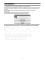
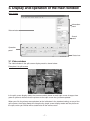
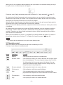
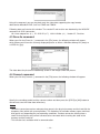
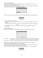
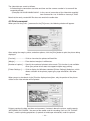
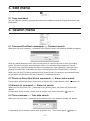
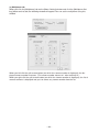
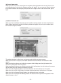
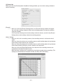
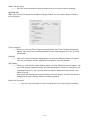
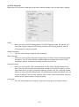
PC PLAYBACK SOFTWARE
DIGITAL RECORDER OPTION
MODEL
DX-PC25EA
Ver.1.0
OPERATION MANUAL
– For Windows® 98SE –
– For Windows® Me –
– For Windows® 2000 –
– For Windows® XP –
This operation manual is important to you. Please read this before using the software.
End User Software License Agreement
Mitsubishi Electric Corporation and the third party as original development company reserve all
the intellectual property rights to this Software for DX-PC25EA (“Software”) and its associated
operation manual (“Operation Manual”).
Mitsubishi Electric Corporation grants user (“User”) a limited non-exclusive license and right under
this Agreement (“Agreement”) to use this Software.
User may not reverse engineer, de-compile, or disassemble this Software, except and only to the
extent that such activities are expressly permitted by this Agreement and any applicable law.
Unauthorized reproduction, copying, sale, import, export, use, or leasing of either this Software or
its Operation Manual by User, in whole or in part, is strictly prohibited by this Agreement and
Copyright Law.
Software specifications, Software design, and the contents of this Operation Manual are subject to
change without notice to User.
This Software is designed to play, display, copy, and save digitally recorded audio and video data.
Unauthorized copying by User of copyright protected audio and video data is not permitted under
this Agreement or Copyright Law.
Mitsubishi Electric Corporation assumes no responsibility or liability for privacy violation or
copyright infringement or any intellectual property violation by User incurred from transfer of audio
or video data by the User during the use of this Software.
Mitsubishi Electric Corporation assumes no responsibility or liability to User for damages or
demands of any kind incurred during use of this Software.
-2-
Disclaimers
The copyright holder of this software is Mitsubishi Electric Corporation.
Mitsubishi assumes no responsibility for damages or demands or the like relating to the damages
incurred during use of this software in the manner not permitted by the relevant software license
agreement.
Both this software and this instruction manual are subject to change without notice for
improvements.
Reverse engineering and alternations of this software are prohibited.
Take precautions when handling copyright-protected audio-video.
Microsoft and Windows are either registered trademarks or trademarks of Microsoft Corporation in
the United States and/or other countries. (The official name of Windows is Microsoft Windows
operating system.)
IntelliMouse is either registered trademark or trademark of Microsoft Corporation in the United
State and other countries.
This software is partly based on the work of the Independent JPEG Group.
All other company names and product names appearing herein are the property of their respective
owners.
-
Windows 98SE is an abbreviation of Microsoft Windows 98 Second Edition.
Windows 2000 is an abbreviation of Microsoft Windows 2000 Professional.
Windows Me is an abbreviation of Microsoft Windows Millennium Edition.
Windows XP is an abbreviation of Microsoft Windows XP.
©2003 Mitsubishi Electric Corporation. All rights reserved.
-3-
Contents
1. Introduction ....................................... 5
9. View menu ....................................... 19
1.1 Product features .................................. 5
1.2 System requirements .......................... 5
1.3 Compatible DVR .................................. 6
9.1 Operation Panel/Status Bar/
Information Panel commands .......... 19
9.2 Quick Zoom command ...................... 19
9.3 Recorder Status command ................ 19
9.4 Picture Size command ...................... 19
9.5 Options command ............................. 20
9.6 Smoothing command ........................ 20
9.7 Audio command ................................. 20
9.8 Camera command ............................. 21
9.9 Overlay command ............................. 21
2. Set-up ................................................. 6
2.1 Installation ........................................... 6
2.2 Uninstallation ....................................... 6
2.3 Starting and exiting .............................. 6
3. Display and operation of the
main window..................................... 7
10. Zoom function ............................... 22
3.1 Video window ...................................... 7
3.2 Operation panel ................................... 8
3.3 Information panel ............................... 10
3.4 Search panel ..................................... 11
3.5 Status bar .......................................... 12
3.6 Shortcuts menu ................................. 12
10.1 Specification of the magnification .... 22
10.2 Specification of the area to be
magnified ......................................... 22
11. Network menu ................................ 23
5. Edit menu ......................................... 17
11.1 Connect command........................... 23
11.2 Disconnect command ...................... 23
11.3 Add recorder command ................... 23
11.4 Recorder list command .................... 25
11.5 Renew info command ...................... 25
11.6 ALM Notification command .............. 25
11.7 Control commands........................... 27
11.8 Config command.............................. 32
5.1 Copy command ................................. 17
12. Special search function ................ 45
6. Search menu .................................... 17
13. Help menu ...................................... 47
6.1 Comment/Find Next commands ........ 17
6.2 Previous Alarm/Next Alarm
commands ....................................... 17
6.3 Alarm List command .......................... 17
6.4 Time command .................................. 17
13.1 Help command ................................ 47
13.2 About command .............................. 47
4 File menu .......................................... 13
4.1 Folder command ............................... 13
4.2 Media command ................................ 13
4.3 Save As command ............................ 14
4.4 Convert command ............................. 14
4.5 Print command .................................. 16
14. Appendices .................................... 47
14.1 Restrictions ...................................... 47
14.2 Networking ...................................... 48
7. Operation menu ............................... 18
7.1 Playback/Stop/Reverse Playback/
Forward Search/Reverse Search/
Field Advance/Field Reverse/
Rewind commands .......................... 18
7.2 Eject commands ................................ 18
8. Bookmarks menu ............................ 18
8.1 Save with the bookmark command .. 18
8.2 Bookmark 1 - 30 commands ............. 18
8.3 Bookmark A and B commands .......... 18
8.4 Repeat between A and B command .. 18
-4-
1. Introduction
Mitsubishi DX-PC25EA is viewing software designed for DX-TL2530E or DX-NT430E Digital Video
Recorder (“DVR”). With this software, you can view surveillance pictures that are recorded on PCcompatible media such as Compact Flash Card, CD-R/RW, and DVD.
In combination with DX-TL2530E or DX-NT430E digital recorder, you can set and operate the
recorder and load recorded pictures and the latest picture from the recorder using the communication function.
1.1 Product features
- Display of pictures from all the cameras connected with the DVR
- Playback of the data recorded in FSM2 format, and playback of the recorded data that are
copied to other media (within the range Microsoft Internet Explorer applies.)
- Playback of the data recorded on the SCSI copy media in FSMS2 format
- Display of the recording date and time, title, alarm type, and comment
- Comment search, date and time search, alarm index search, and alarm list display and search
- Zoom-in display of still picture
- Camera switching function, and multi-screen (16-split, 9-split, and 4-split) display function
- Printing by Windows-supported printer
- Bookmarking function, and A-B repeat playback function
- Audio playback function (except under certain conditions)
- Saving of still picture in bitmap or JPEG format, and conversion of still picture into AVI format
- Simultaneous playback during recording, latest picture loading, picture download by specifying
the section (via network)
- Remote control and remote setting of the digital recorder (via network)
- PTZ camera control (via network)
- Firmware updating function (via network)
- Alarm notification receiving function
1.2 System requirements
To use DX-PC25EA, you need:
- IBM PC/AT-compatible with Intel Pentium processor or Intel Celeron processor (500 MHz or
faster)
- Microsoft Windows 98SE, Windows Me, Windows 2000, or Windows XP
- RAM of 256 MB or more
- Video card and monitor with 1024 pixels by 768 lines (XGA) or more (recommended) and
32,000 colors for display
- Drive that can read CD-R discs
- Free hard disk space of 200 MB or more at the time of installation
- Free hard disk space for the swap depending on the swap size at the time of collective conversion
- SCSI adapter supporting WINASPI32 and SCSI-2 such as Adaptec AHA-2940 Series and
SlimSCSI (only when SCSI-connected peripheral devices are used.)
With Windows 2000 and Windows XP, WinASPI must be installed in advance for playback on
SCSI-connected devices. For installation of WinASPI, please read the instruction manual of
Adaptec SCSI board.
- Windows-supported sound adaptor such as SoundBlaster
- Microsoft Internet Explorer 5.01 Service Pack 2 or later (Prior installation is required.)
- NIC that operates correctly under the condition satisfying the above-mentioned requirements
(Required when the communication function is used.)
-5-
Note:
- Operation is not always guaranteed under any environment that satisfies the system
requirements above.
1.3 Compatible DVR
- DX-TL2530E
- DX-NT430E
Note:
- This manual describes operation of 16-ch digital recorder.
- With 4-ch digital recorder such as DX-NT430E, this software may not operate in a manner
consistent with descriptions herein regarding the number of channels (or number of screens).
For example, the [4x4] and [3x3] buttons don’t work.
- With media recorded by a digital recorder that has no multiplexer, the multiplexer function (or
function related to the [Camera] command of the [View] menu) doesn’t work.
2. Set-up
2.1 Installation
To install DX-PC25EA, first start SETUP.EXE contained in the provided CD. Follow a series of
instructions that appears on the screen, and the software will be installed automatically.
The default directory for installation is C:/Program Files/DX-PC25EA.
2.2 Uninstallation
To uninstall DX-PC25EA, display the [Add or Remove Programs] dialog box by selecting from
[Control Panel] and select DX-PC25EA to delete. Alternatively, select the [Uninstall DX-PC25EA]
command from the [Start] menu and follow a series of instructions that appears on the screen.
2.3 Starting and exiting
DX-PC25EA is registered in the [Start] menu after the completion of installation. To start the program, select DX-PC25EA from the [Start] menu, and the main window will appear on the screen.
To exit the program, go to the [File] menu and select [Exit].
-6-
3. Display and operation of the main window
Main window
Information
panel
Video window
Search
panel
Operation
panel
Status bar
3.1 Video window
The video window in the split screen display mode is shown below.
Example of 16-split screen
In the split screen display mode, the camera number shown on each split screen changes from
green to yellow to indicate that the picture on that split screen has just been updated.
When you click the primary mouse button (or the left button in the standard setting) on any of the
split screens, the display mode will change to the single screen display mode and the picture on
the split screen you clicked will be stretched to fill the entire screen.
-7-
When you click the secondary mouse button (or the right button in the standard setting) on any of
the split screens, the following menu will appear.
For details of the [Copy] command, please refer to Section 5.1 “Copy command” (
page 17).
By selecting the [Assign] command and a camera number, you can assign the selected camera
number to the split screen you clicked. The assigned camera number will be saved in the registry
and appear on that position from the next start of the program.
When the [Save Layout] button is held down, the picture layout in the split screen display mode is
saved and such layout is used from the next start of this software.
When you select the [Reset] command, assignment of the camera numbers on all the split screens
is initialized.
By selecting the picture quality level using the [Quality] command, you can change the quality of
live pictures. However, only one person is authorized to change the picture quality per digital
recorder. Therefore, you may not able to change the picture quality depending on your authority
given at the time of connection.
When you select [Mode Out Control...], the [Mode Out Control] window will appear. For details of
page 31).
this function, please refer to Section 11.7.4 “Mode Out Control command” (
Note:
- The refresh rate may decrease in the split screen display mode.
3.2 Operation panel
With DX-PC25EA, you can play back the pictures recorded by the DVR.
Function of each button is described below.
Button
Command
Function
Rewind
Click to jump to the head of the recorded data.
Reverse search
Click to play the video in the reverse direction with a higher speed
than normal playback. The search speed changes from X1 to X2,
X4, X8, and back to X1 at every press of this button. You can
specify the number of fields skipped in search using in the [Options] command in the [View] menu.
Reverse playback
Click to play the video in the reverse direction.
Field reverse
Click to display a still picture one field before.
Stop
Click to stop playing back the video. Audio, if recorded, will be
played back after stop when the audio command has been enabled.
Field advance
Click to display a still picture one field after.
Play
Click to play the video in the forward direction.
-8-
Forward search
Click to play the video in the forward direction with a higher speed
than normal playback. The search speed changes from X1 to X2,
X4, X8, and back to X1 at every press of this button. You can
specify the number of fields skipped in search using in the [Options] command in the [View] menu.
Bookmark
Click to save the picture being displayed on the screen as a
bookmark.
Renew Info.
Click to load the latest information while communicating with the
recorder.
Live
Click to load the latest picture while communicating with the
recorder. (Audio isn’t reproduced during this loading process.)
If the recorder isn’t on, the picture stored in the memory that was
being displayed when the recorder was turned off last time is
displayed.
Device
Use to select a device to play. (Default: Main)
Position slider
Shows the position of the picture in the video sequence.
The indication by the position slider is based on the volume of the
recorded data, not on the time.
Note that the position slider doesn’t work nor appear on the
screen while DX-PC25EA while in communication.
Button
Command
Function
Camera number
Click to activate the camera corresponding to the number of the
button to display the picture from such camera. When more than
one camera is selected in the single screen display mode, pictures from those cameras are switched alternately.
4Multi
Click to change to the 4-split screen display mode. The display
pattern changes from 4a to 4b, 4c, 4d, and back to 4a at every
press of this button. In the default setting, 4a consists of channel
1-4, 4b of channel 5-8, 4c of channel 9-12, and 4d of channel
13-16.
9Multi
Click to change to the 9-split screen display mode. The display
pattern changes from 9a to 9b, and back to 9a at every press of
this button. In the default setting, 9a consists of channel 1-9, 9b
of channel 10-16,1, and 2.
16Multi
Click to change to the 16-split screen display mode.
Save Layout
Click to save the picture layout that is used when the 4-split or 9split screen mode is activated.
to
-9-
Playback speed slider
Click to adjust the playback speed. (Default: Fast)
When the slide is at the [Fast] position (default), pictures are
refreshed at the highest refresh rate. At the [Slow] position,
pictures are refreshed at intervals of the highest refresh rate plus
3 seconds per picture. You can adjust the playback speed in 100
steps between [Fast] and [Slow].
You can select whether to display or hide the operation panel. To select, go to the [View] menu and
select the [Operation Panel] command.
You can operate the playback operetion buttons using the [Operation] menu, alternatively.
You can operate the [Bookmark] button using the [Save with the bookmark] command in the
[Bookmark] menu, alternatively.
You can operate the [1] to [16] buttons, [2x2], [3x3], and [4x4] buttons using the [Camera]
command in the [View] menu, alternatively.
3.3 Information panel
You can select whether to display or hide the information panel (and the search panel). To select,
go to the [View] menu and select the [Information Panel] command.
3.3.1 Media Information box
This box displays the recording period of the selected medium.
During playback of the recorded pictures via network, the names of the connected recorder and
camera, recording period, and state of the recorder are displayed.
During loading of the latest picture via network, the names of the connected recorder and camera
and state of the recorder are displayed. When the connected recorder isn’t on, the recording
period isn’t displayed.
The media information is automatically renewed at fixed intervals (or every 3 minutes by default).
During playback of copied data
During playback of
recorded data via network
During loading of the latest
picture via network
3.3.2 Image Information box
This box displays the recording data such as recording date and time, camera number, and
comment, if any.
In the split screen display mode, the information of the last refreshed pictures (or the pictures
whose camera number is yellow on the video window) is displayed.
During loading of the latest picture via network, only the camera numbers are displayed.
When an alarm-recorded picture is displayed, a red dot appears to the right of the title [Image
Information].
During loading of the latest picture via network, the red dot doesn’t appear.
When an alarm-recorded picture
is displayed, a red dot appears.
EXT. DATA is displayed.
(DX-TL2530E only)
- 10 -
3.3.3 Picture Size box
You can change the size of the picture by entering your desired magnification in %.
The magnification range is from 25% to 800%.
For details of the zoom function, please refer to Section 10 “Zoom function” (
page 22).
3.4 Search panel
You can select whether to display or hide the search panel (and the information panel). To select,
go to the [View] menu and select the [Information Panel] command.
3.4.1 Time Search panel ---- Time date search
you can search for a specific scene based on its recording date and time.
To search for a scene, just specify the date and time and then click the [Search] button.
DX-PC25EA displays a picture recorded exactly at the specified time or around such time.
While in communication, a picture recorded most close to the specified time on the specified day is
retrieved. If there is no picture recorded on the specified day, nothing is displayed.
You can operate the time date search using the [Time...] command in the [View] menu, alternatively.
3.4.2 Alarm List panel ---- Alarm list search
When you click the [Show List] button, the following window will appear.
You can display your desired alarm picture by selecting the alarm from the list and clicking the
[Search] button.
You can save the alarm list as a tab-delimited text file by clicking the [Save...] button.
You can sort the listed items based on your desired column by clicking the title of the column.
When a medium of FSMS-series format is used, the column of alarm type may not be displayed.
You can operate the alarm list search using the [Alarm List ...] command in the [View] menu,
alternatively.
- 11 -
3.4.3 Index Search panel ---- Alarm index search
When you click the [<] (previous alarm) button or the [>] (next alarm) button, the alarm-recorded
pictures are searched toward the oldest recorded picture or the latest recorded picture respectively.
.
While in communication, the number of skipped alarms varies depending on the number of indexes
determined on the recorder’s side.
You can operate the alarm list search using the [Previous Alarm...] or the [Next Alarm ...]
command in the [View] menu, alternatively.
3.5 Status bar
The status bar displays the explanation of the selected menu or button, the current playback mode,
and the current display range.
You can select whether to display or hide the status bar. To select, go to the [View] menu and
select the [Status Bar] command.
3.6 Shortcuts menu
When you click the secondary mouse button (or the right button in the standard setting) anywhere
on the picture, the following shortcuts menu will appear.
For details of [Copy] command, please refer to Section 5.1 “Copy command” ( page 17).
For details of [Picture Size] command, please refer to Section 9.4 “Picture Size command” (
page19).
page 7).
For details of [Assign] command, please refer to Section 3.1 “Video window” (
When you select [Mode Out Control...], the [Mode Out Control] window will appear. For details of
this function, please refer to Section 11.7.4 “Mode Out Control command” (
page 31).
- 12 -
4 File menu
4.1 Folder command
When you click the [Folder...] command in the [File] menu, the following window will appear. You
can play back the video data contained in the folder.
Using this command, you can play back only the video data supporting the copy formats
dedicated to Mitsubishi DVR, such as FSM1 and FSM2.
The FSM2-supported data are comprised of the following files as a rule. If any of these files is
missing, operation and performance of the DVR are not guaranteed. Even when all of these files
exist, data may not be played back depending on their type (for example, the data of which file was
copied from another compact flash card cannot be played back), and operation and performance of
the DVR are not guaranteed.
File configuration of FSM2-supported data
ALRM25 (Alarm list file)
DEVC25 (Device data file)
PIRT25 (Partition data file)
SRCH25 (Search data file)
ESRC25 (Extended search data file)
TL001 (Video data folder)
D00000.TLX (Video file)
D00001.TLX (Video file)
D00002.TLX (Video file)
:
4.2 Media command
When you click the [Media...] command in the [File] menu, the following window will appear. You
can select a medium from the window.
- 13 -
Using this command, you can play back only the video data supporting the copy formats
dedicated to Mitsubishi DVR, such as FSMS and FSMS2.
Following data are listed on this window. The vendor ID and revision are obtained by the INQUIRY
command via SCSI connection.
HA : Host adaptor No. (0- ), ID: SCSI ID (0-7), LUN: LUN No. (0- ), Vendor ID, Revision
4.3 Save As command
When you click the [Save As...] command in the [File] menu, the following window will appear,
which allows you to save the currently displayed picture as either a Windows bitmap file (.bmp) or
a JPEG file (.jpg).
The data about the picture are additionally shown in the margin under the picture.
4.4 Convert command
When you click the [Convert...] command in the [File] menu, the following window will appear.
Specify the recording period and the camera number and then press the [JPEG] or [AVI] button to
convert and save the video data collectively.
Note:
- Collective conversion requires adequate free space in the physical memory and the hard disk for
temporary files (within the system partition). The limitations of available memory space and hard
disk space vary depending on your operating conditions. Perform conversion starting from a
small file that requires only several seconds to be converted while checking the state of the
memory and the hard disk.
- This function isn’t available while in communication.
- 14 -
To convert into JPEG file:
When you press the [JPEG] button, the following window for specifying the folder where the
converted video data are saved will appear.
When you press the [OK] button after specifying the folder, collective conversion will start and the
window showing the progress of the conversion will appear.
When the conversion completes, [Generation of JPEG was completed successfully.] will appear.
The video data are saved as follows.
- A folder bearing the conversion start date and time in its name will be created in the folder you
specified.
(Example) 09012005123456 : In the case of conversion performed at 12:34:56 on January 9,
2005.
- Serial-numbered JPEG files are created in the automatically created folder starting from
“D00000.jpg”.
To convert into AVI file:
When you click the [AVI] button, the following window for setting the AVI file will appear.
[Image Size] ----- Select the size of the picture contained in the AVI file among three choices below.
[Large] : 981 x 720 pixels, [Normal] : 654 x 480 pixels, [Small] : 327 x 240 pixels
[Frame Rate] ---- Select the speed to play back the AVI file among five levels from [Fast] to [Slow].
When you press the [Convert] button while this window is being displayed, the window for
specifying the folder where the AVI file is saved will appear.
When you press the [Save] button after specifying the folder, collective conversion will start and
the window showing the progress of the conversion will appear.
When the conversion completes, [Generation of AVI was completed successfully.] will appear.
- 15 -
The video data are saved as follows.
- A file bearing the conversion start date and time and the camera number in its name will be
created by default.
(Example) 09012005123456C09.AVI : In the case of conversion of the video data supplied
from Camera No. 9 at 12:34:56 on January 9, 2005.
Note that the newly created AVI file does not contain the audio data.
4.5 Print command
When you click the [Print...] command in the [File] menu, the following window will appear.
After setting the margin, printer, and other options, click the [Print] button to print the picture being
displayed.
[Preview] ----------------- Click to view what the printout will look like.
[Margin] ------------------ Enter desired margins in millimeters.
[Number of copies] ---- Specify the number of printouts to be made. This function is not available
when your printer driver does not support multiple copy printing.
[Printer Settings...]----- Click to display the Windows standard [Printer Settings] dialog box, which
allows selection of the printer, paper type, page orientation, and other
items.
When you put a checkmark in the [Print the displayed area] box, only the portion of the picture
visible on the video window will be printed.
Printout contains the date and time and comment, if entered, above the picture, and the words
“MITSUBISHI DX-PC25EA,” the name of the model used for recording (such as “DX-TL2500E
Series”), and the printing proportions (in portrait or landscape orientation) under the picture.
- 16 -
5. Edit menu
5.1 Copy command
You can copy the currently displayed picture onto the clipboard using the [Copy] command in the
[Edit] menu.
6. Search menu
6.1 Comment/Find Next commands ---- Comment search
When you click the [Comment...] command in the [Search] menu, the following window will appear.
Enter any words based on which your desired picture is searched for and click the [Find Next]
button. A picture having the entered search words in its comment will be displayed, if found.
The pictures are searched toward the oldest recorded picture when [Upward] is selected in the
[Search Direction] field, and toward the latest recorded picture when [Downward] is selected.
When you click the [Find Next] command in the [Search] menu, the pictures are searched based
on the words you specified using the [Comment...] command last time.
6.2 Previous Alarm/Next Alarm commands ---- Alarm index search
For operation of these functions, please refer to Section 3.4.3 “Index Search panel” (
page 12).
6.3 Alarm List command ---- Alarm list search
When you click the [Alarm List...] command in the [Search] menu, the [Alarm list] window will
appear.
For operation of this function, please refer to Section 3.4.2 “Alarm list panel” ( page 11).
6.4 Time command ---- Time date search
When you click the [Time...] command in the [Search] menu, the following window will appear.
For operation of this function, please refer to Section 3.4.1 “Time Search panel” (
- 17 -
page 11).
7. Operation menu
7.1 Playback/Stop/Reverse Playback/Forward Search/Reverse Search/
Field Advance/Field Reverse/Rewind commands
For operation of these commands, please refer to Section 3.2 “Operation panel” (
page 8).
7.2 Eject command
When you select the [Eject] command in the [Operation] menu, the medium currently selected will
be ready for ejection from the drive.
8. Bookmarks menu
8.1 Save with the bookmark command
You can save the current playback position as a bookmark by the [Save with the bookmark]
command in the [Bookmarks] menu.
Up to 30 bookmarks can be saved. When you save more than 30 bookmarks, they will be erased
from the oldest one. All the bookmarks are erased either when you change the playback device or
when you exit DX-PC25EA.
This command has the same function as the [Bookmark] button on the operation panel.
8.2 Bookmark 1 - 30 commands
You can jump to any bookmark by selecting among the bookmark [1-30] commands in the
[Bookmarks] menu.
8.3 Bookmark A and B commands
Using the bookmark [A] or [B] command in the [Bookmarks] menu, you can save the current
playback position as Point A or Point B to repeat playback between those positions.
8.4 Repeat between A and B command
By putting a checkmark to the [Repeat between A and B] command in the [Bookmarks] menu, you
can repeat playback between Point A and Point B you specified.
- 18 -
9. View menu
9.1 Operation Panel/Status Bar/Information Panel commands
By clicking the [Operation Panel] command in the [View] menu, you can select whether to display
or hide the operation panel. Similarly, you can select whether to display or hide the status bar or
the information panel/search panel by clicking the [Status Bar] command or the [Information Panel]
command respectively. These settings are saved in the registry.
9.2 Quick Zoom command
By clicking the [Quick Zoom] command in the [View] menu, you can select whether to display or
hide the quick zoom window. This setting is saved in the registry.
For details of the zoom function, please refer to Section 10 “Zoom function” ( page 22).
9.3 Recorder Status command
When you click the [Recorder Status] command in the [View] menu, the following window will
appear.
[Recorder Status] window
This window shows the operation status of the connected recorder.
By clicking the colored indicators, you can stop the operations represented by those indicators.
You can’t start the operations by clicking those indicators.
(To start operations, use the [Control] command of the [Network] menu referring to Section 11.7.1
page 27).)
“Control command” (
The operation status shown on this window is renewed when the [Control] command described in
page 27) or [Renew Info] command described in Section
Section 11.7.1 “Control command” (
page 25) of the [Network] menu is executed.
11.5 “Renew info” command (
By default, the operation status is automatically renewed every 3 minutes.
9.4 Picture Size command
When you click the [Picture Size...] command in the [View] menu, the options of [25%], [50%],
[75%], [100%], [200%], [400%], and [800%] will appear. Images are zoomed in or out according to
the selected magnification.
When you select the [Fit to the window] command, the magnification is automatically adjusted so
that the displayed image is fit to the window. This automatically adjusted magnification is saved in
the registry.
- 19 -
For details of the zoom function, please refer to Section 10 “Zoom function” (
page 22).
9.5 Options command
When you click the [Options...] command in the [View] menu, the following dialog box will appear.
[Number of fields in search](PC Data) -- You can specify the number of pictures to skip in forward
search or reverse search.
[Audio Play] ------------------------------------ You can select the number of blocks to play back the
audio among [Short], [Medium], and [Long].
[Number of steps in search] (Network) -- You can specify the number of pictures to skip in forward
search or reverse search during playback via network.
[Renew Info.]----------------------------------- You can specify the interval of automatic information
renewal.
Click the [OK] button to save the settings in the registry.
9.6 Smoothing command
When you put a checkmark to the [Smoothing] command in the [View] menu, the picture will be
smoothed at the time of stop. This setting is saved in the registry.
9.7 Audio command
When you put a checkmark to the [Audio] command in the [View] menu, audio will be output while
a medium containing recorded audio is played. When playback of such medium is stopped with the
audio function enabled, the audio both prior to and subsequent to the frame at the stop will be
output.
You can set the duration of audio playback using [Audio Play ] of the [Options] command in the
[View] menu.
Note:
- The length of the period of audio playback is affected by the settings made at the time of
recording of the audio on that medium (such as recording interval and recorded picture quality).
- 20 -
9.8 Camera command
You can select a camera for playback by the [Camera] command in the [View] menu.
[16Multi], [9Multi], [4Multi], [No.1] to [No.16]
--------------------- For operation of these commands, please refer to Section 3.2 “Operation panel”
pages 8 and 9).
(
[All] ---------------- You can display pictures from all the cameras, switching them sequentially.
9.9 Overlay command
You can select data to display on the screen by the [Overlay] command in the [View] menu.
[Camera No.] --- Use to display the camera number.
[Alarm Mode] --- Use to display the alarm type when an alarm-recorded picture is displayed.
[Title] -------------- Use to display the camera title, if any.
- 21 -
10. Zoom function
10.1 Specification of the magnification
You can specify the magnification using any of the following methods.
- Specify the magnification within the range from 25% to 800% using the [Picture Size] box on the
main window.
- Specify the magnification using the [Picture Size] command in the [View] menu. Refer to Section
page 19).
9.4 “Picture Size command” (
- Specify the area to be magnified by dragging the mouse on the [Quick zoom] window. The area
to be magnified is enclosed by a box. For how to display or hide the [Quick zoom] window, refer
page 19).
to Section 9.2 “Quick Zoom command” (
- Specify the magnification in 50% steps within the range from 25% to 800% by turning the wheel
of Microsoft IntelliMouse while holding down the [Ctrl] key.
The main window (including the [Quick zoom] window) during zooming is shown below.
[Picture Size] box
[Quick zoom]
window
Specified area
10.2 Specification of the area to be magnified
You can specify the area to be magnified using any of the following methods.
- Scroll the picture using the scroll bar appearing on the video window during zooming.
- Drag the picture to scroll it in your desired direction.
- Specify the area to be magnified by dragging the mouse on the [Quick zoom] window. The area
to be magnified is enclosed by a box. For how to display or hide the [Quick zoom] window, refer
page 19).
to Section 9.2 “Quick Zoom command” (
- Turn the wheel of Microsoft IntelliMouse. (The picture moves upward or downward only.)
- 22 -
11. Network menu
DX-PC25EA is capable of remote playback of the digital recorder and PTZ camera control using its
communication function. For general networking, please refer to Section 14.2 “Networking” (
page 48).
11.1 Connect command
When you click the [Connect] command in the [Network] menu, you will be connected to the digital
recorder being selected on the recorder list window. This command is unavailable unless the
recorder list window is being displayed.
11.2 Disconnect command
When you click the [Disconnect] command in the [Network] menu, you will be disconnected from
the currently connected digital recorder. This command is unavailable unless DX-PC25EA is
communicating with a digital recorder.
11.3 Add recorder command
When you click the [Add recorder...] command in the [Network] menu, the recorder list window will
appear. You can add or delete the networked digital recorders and edit their information using this
window.
Up to 800 recorders can be registered in DX-PC25EA. When digital recorders are registered in
DX-PC25EA, the recorder list window will automatically appear from the next startup.
There are two types of the recorder list window: detailed type and simple type.
To display the recorder list window of detailed type, put a checkmark in the [Details] box on the
recorder list window.
Recorder list window (detailed type)
Recorder list window (simple type)
To expand the fields and view hidden characters, drag the borders between the fields (DVR Name,
Camera Name, Recorder Ch, IP Address, and Info Port) of the list.
- 23 -
11.3.1 Connection and disconnection
When you click the [Connect] button on the recorder list window and enter your user name and
password on the login window, you will be connected to the selected digital recorder that is highlighted in the list.
Enter the user name and password that have been registered in the digital recorder you want to
access. In DX-TL2530E and DX-NT430E digital recorders, the default user name and password
are as follows:
Administrator user
User name: root
Password: admin000
General user
User name: guest
Password: guest
By selecting another digital recorder and clicking the [Connect] button while you are communicating with the selected recorder, you will be disconnected from the selected recorder and connected
to such another recorder.
When you click the [Disconnect] command on the recorder list window, you will be disconnected
from the digital recorder you are communicating with. This button doesn’t work unless you are
communicating with a digital recorder.
11.3.2 Registration - Available on the recorder list window of detailed type only
When you click the [Add...] button on the recorder list window of detailed type, the [Recorder
Property] window will appear. You can add digital recorders using this window.
[DVR Name] (optional) ------- Enter the name of the digital recorder to register.
[Camera Name] (optional) --- Enter the name of the camera (or installation location) to register.
[IP Address] (essential) ------ Enter the IP address of the digital recorder to register. When
registering a DX-TL2530E or DX-NT430E digital recorder, enter the
IP address shown on its <ETHERNET> screen. DX-PC25EA communicates with the digital recorder based on this number. If you enter a
wrong number, DX-PC25EA doesn’t communicate correctly. In addition, duplicate IP addresses aren’t accepted.
[Recorder Ch] (optional) ----- You can select a camera or saved screen layout to use at the time of
connection.
[Info Port No.] (essential) ---- Enter the information port number of the digital recorder to register.
This number should be consistent with the setting value of the digital
recorder to be registered. When registering a DX-TL2530E or DXNT430E digital recorder, enter the number shown by [USER ACCESS] on the <SERVICE PORT SETTING> screen. The number
“53705,” which is the initial setting of DX-TL2530E and DX-NT430E
digital recorders, is displayed by default. DX-PC25EA communicates
with the digital recorder based on this number. If you enter a wrong
number, DX-PC25EA doesn’t communicate correctly.
- 24 -
When you click the [OK] button after entering all necessary information, the entered information is
displayed on the recorder list window.
When you click the [Cancel] button, all the entered information is deleted and registration is canceled.
11.3.3 Edit - Available on the recorder list window of detailed type only
When you click the [Edit...] button on the recorder list window of detailed type while a desired
digital recorder is being selected, the [Recorder Property] window (shown in Section 11.3.2) of the
selected recorder will appear. You can change the information of the digital recorder using this
window.
When you click the [OK] button after changing the information, the information of the recorder is
displayed in the list as changed.
When you click the [Cancel] button, all the changes you are making are canceled and the information of the recorder remains unchanged.
11.3.4 Deletion - Available on the recorder list window of detailed type only
When you click the [Delete] button on the recorder list window of detailed type while a desired
digital recorder is being selected, the following confirmation window as shown on the right will
appear.
When you click the [OK] button, the information of the selected digital recorder is deleted.
When you click the [Cancel] button, the information of the selected digital recorder remains unchanged.
11.4 Recorder list command
When you click the [Recorder list...] command in the [Network] menu, the recorder list window will
appear. When digital recorders are registered in DX-PC25EA, the recorder list window will automatically appear from the next startup.
For details of the recorder list window, please refer to Section 11.3 “Add recorder command” (
page 23).
11.5 Renew info command
By clicking the [Renew info] command in the [Network] menu, you can load and update various
data. (The [Renew Info.] button on the main window works the same as this command.)
For the interval of automatic information renewal, please refer to Section 9.5 “Option command”
page 20).
(
11.6 ALM Notification command
11.6.1 Setting
When you click the [ALM Notification...] command in the [Network] menu, the [Alarm Notification
Setting] window will appear. You can make settings for receipt of alarm notification from the digital
recorder.
- 25 -
[Listening Port] ----------------- Enter the number of the port to receive alarm notification.
In the case of a DX-TL2530E or DX-NT430E digital recorder, enter
the number shown by [TARGET] on the <ALARM NOTIFICATION
SETTING> screen.
[Popup Message] -------------- Select the events you want to be informed by popup message at the
time of receipt of alarm notification.
In the case of a DX-TL2530E or DX-NT430E digital recorder, only the
events selected by checkmarks are indicated by popup message
when [ALARM SENS], [REC MODE], and [WARNING] of the
<ALARM NOTIFICATION SETTING> screen have been set to ON
respectively.
11.6.2 Receipt
When an alarm notification is received, the following popup message will appear.
When the audio speaker of the personal computer is on, receipt of an alarm notification is indicated
by a sound.
The latest alarm notification is displayed at the top of the list.
Separate popup messages appear for every IP address of the digital recorder that issued alarm
notification.
The name and IP address of the digital recorder that issued alarm notification (that have been
registered in the recorder list) are displayed.
When you click the [Connect] button, DX-PC25EA will automatically start and access the digital
recorder that issued alarm notification. This button doesn’t work unless the IP address of the
digital recorder that issued the received alarm notification has not been registered in the recorder
list.
When you click the [OK] button, the popup message window will disappear.
- 26 -
Note:
- When a NAT or router with IP masquerade exists between the digital recorder and the personal
computer, the IP address of the recorder becomes inconsistent with that shown on the recorder
list window and you will be connected to a wrong digital recorder.
- When an alarm occurs during normal recording, alarm notification packet is transmitted at the
start of alarm recording and at the resumption of normal recording subsequent to the end of the
alarm recording.
- The displayed date and time indicate when the digital recorder processed the alarm notification
internally, and they aren’t the exact date and time when the alarm notification was issued.
- The digital recorder doesn’t issue another alarm notification before the current alarm notification
is completed. If there is no response from the digital recorder that issued alarm notification, the
next alarm notification is suspended until the retry process is completed.
- The digital recorder can retain approx. 100 alarm notifications in its buffer. Recent alarm notifications exceeding the capacity of its buffer are discarded.
- The liability of the alarm notification function isn’t absolute. Don’t use it for making critical judgment nor for any purposes related to human lives.
11.7 Control commands
11.7.1 Recorder Control command
When you click the [Recorder Control...] command of the [Control] command in the [Network]
menu, the following window will appear. You can control the operation of the connected digital
recorder.
When this window appears, refreshing of live pictures and playback are automatically stopped.
This command is unavailable unless the [Control] authority described in Section 11.8.1 “User
Maintenance command” (
page 32) is effective.
Moreover, it is unavailable when the [SUPER USER] port of the digital recorder is being used by
other user of DX-PC25EA.
- 27 -
Statuses of the operations (such as recording) that are started immediately by press of the correpage 19).
sponding buttons are displayed on the [Recorder Status] window (
The buttons on the [Recorder Control] window work in the almost same way as the buttons on the
digital recorder.
The [Select -] and [Select +] buttons correspond to the jog of the digital recorder, and the [Clear]
and [Enter] buttons correspond to the shuttle.
For playback, click the [Playback Mode] button to activate the playback mode, and adjust the
playback speed using the playback speed slider.
Note
- When you change the screen layout of the digital recorder using the [SPRIT] button, the layout
set by this window may not be consistent with that is actually output from the digital recorder. In
such cases, press the [SPRIT] button several times until the screen layouts become consistent.
(In most cases, they become consistent each other when the [SPRIT] button is pressed several
times.)
- This window doesn’t always display the status of the digital recorder correctly. To display the
latest status, click the [Renew Info] button.
11.7.2 PTZ Cam Control command
When you click the [PTZ Cam Control...] command of the [Control] command in the [Network]
menu, the following window will appear. You can control the camera operation using this window.
When this window appears, refreshing of live pictures and playback are automatically stopped.
This command is unavailable unless the [Control] authority described in Section 11.8.1 “User
page 32) is effective. Moreover, it is unavailable when the [SUPER
Maintenance command” (
USER] port of the digital recorder is being used by other user of DX-PC25EA.
This command has effect only on the cameras that support the function of this command.
- 28 -
The name and IP address of the connected digital recorder are displayed at the top this window.
You can select the camera number using the pull-down list box on the video window.
When you click the arrowhead symbols (corresponding to 8 directions) around the video window,
the camera angle moves in respective directions. When you click the slanting arrowhead symbols,
the camera angle moves one step upward or downward and one step to the left or right.
When you drag anywhere on the view window, a small arrowhead symbol will appear and you can
continuously move the camera angle in the direction of the symbol.
[Zoom] ---------------------------- Click the [Wide] button to zoom out, and click the [Tele] button to
zoom in. Click the button again to stop zooming in or out.
[Focus] --------------------------- Click the [Near] button to focus near, and click the [Far] button to
focus far. Click the [Auto] button to automatically adjust the focus.
[Iris] -------------------------------- Click the [-] button to close the iris, and click the [+] button to open the
iris. Click the [Auto] button to automatically adjust the iris.
[Preset Position] --------------- To register the current camera angle as a preset, select a preset
number and click the [Register] button. Up to 16 presets can be
registered.
To use a preset camera angle, select a preset number and click the
[Jump] button.
[Command Interval] ----------- You can set the intervals of vertical and horizontal movement of the
camera angle when it is changed in the slanting directions. When the
interval is set to an extremely small value, the camera angle doesn’t
move in slanting directions. Set the interval to a proper value depending on the camera.
[Auto Pan] ----------------------- Use to operate the automatic panning. You can adjust the speed of
automatic panning.
To save the ends of the camera movement range, click the [Position
A] button (for the start position) and the [Position B] button (for the
end position).
[Function] ------------------------ You can register other functions in these buttons.
When you left-click an empty button, a registration window will appear. Right-click to change or delete the registered data.
Up to 10 characters can be used for indication on each button.
11.7.3 Section Download command
When you click the [Section Download...] command of the [Control] command in the [Network]
menu, the following window will appear. You can download recorded pictures from the connected
digital recorder by specifying the period and camera number.
When this window appears, refreshing of live pictures and playback are automatically stopped.
This command is unavailable unless the [Playback] authority described in Section 11.8.1 “User
Maintenance command” (
page 32) is effective. Moreover, it is unavailable when the [SUPER
USER] port of the digital recorder is being used by other user of DX-PC25EA.
- 29 -
The name and IP address of the connected digital recorder are displayed at the top this window.
[Download Section] ----------- Specify the period of the recorded data you want to download.
By default, [Start] displays the current playback time and date and
[End] displays the time and date 5 minutes later.
[Camera No. Selection] ------ Specify the number of the camera you want to download.
When you click the [Download] button, a dialog box to specify the directory to save the downloaded
data will appear. When you specify the directory and click the [OK] button, download will start.
During download, the date and time of the image data being loaded and the number of already
downloaded pictures are displayed at the lower left of the window.
When you click the [Cancel] button, download is canceled.
When download is canceled by occurrence of a communication error or press of the [Cancel]
button, you can resume the download by pressing the [Continue] button within 10 minutes.
The downloaded image data are saved in the pseudo FSM2 format. These data can be played
back by DX-PC25EA. However, they can’t be played back by the digital recorder even though
copied on media such as CompactFlash card.
Note
- This function is for downloading data by specifying the period and not suitable for making
backup copies.
- When download takes several hours to complete, operation during such download isn’t guaranteed.
- Under bad networking conditions, loss of pictures may occur.
- For efficient download, it is recommended to select only one camera in the [Camera No. Selection] column.
- For stable download, it is recommended to select all the cameras including inactive cameras
(1-16 for DX-TL2530E digital recorder, and 1-4 for DX-NT430E digital recorder) in the [Camera
No. Selection] column.
- 30 -
11.7.4 Mode Out Control command (DX-NT430E only)
When you click the [Mode Out Control...] command of the [Control] command in the [Network]
menu, the following window will appear. You can control the MODE OUT terminals on the rear of
the connected digital recorder.
When this window appears, refreshing of live pictures and playback are automatically stopped.
This command is unavailable unless the [Control] authority described in Section 11.8.1 “User
page 32) is effective. This command has effect only on the digital
Maintenance command” (
recorders that support the Mode Out control function.
[Channel] ------------------------ When you click a number button, the live images from the camera
corresponding to the button you pressed are displayed.
[Mode Out] ---------------------- You can turn on or off the MODE OUT terminals on the rear of the
digital recorder.
By right-clicking the buttons in the [Mode Out] column, you can change the names of the buttons.
When the Mode Out settings aren’t LAN on the digital recorder’s side, the lamps under the buttons
are off and you can’t control the Mode Out terminals. In this case, by clicking the lamps to turn
them on, you can enable the Mode Out settings (or select LAN).
However, note that you can’t disable the Mode Out settings (or can’t change the settings of the
digital recorder to other than LAN) using this screen.
For detailed specifications such as output from the MODE OUT terminals, please refer to the
operation manual of the digital recorder.
You can call up the [Mode Out Control] window by right-clicking anywhere on the video window of
the main window alternatively. In this case, the camera right-clicked is automatically selected on
the [Mode Out Control] window.
- 31 -
11.8 Config command
11.8.1 User Maintenance command
When you click the [User Maintenance...] command of the [Config] command in the [Network]
menu, the following window will appear. You can make settings related to management of users
using this window.
When this window appears, refreshing of live pictures and playback are automatically stopped.
Unless the [Regist] authority of this command is effective, you can’t register the recorder settings in
the digital recorder. Moreover, this command is unavailable when the [SUPER USER] port of the
digital recorder is being used by other user of DX-PC25EA.
The name and IP address of the connected digital recorder are displayed at the top this window.
[Load] (DVR) -------------------- Click to load the setting data from the digital recorder.
[Regist] (DVR) ------------------ Click to register the settings shown on the window in the digital
recorder.
[Load] (PC) ---------------------- Click to load the user setting file saved in the personal computer.
[Save] (PC) ---------------------- Click to save the settings shown on the window as a user setting file
in the personal computer.
[DVR User list]------------------ When you put a checkmark in the boxes of the operations, the
authority for those operations are given to the relevant users.
[User ID]-------------------- Enter the name of the user to register.
[Password] ----------------- Enter the password for the registered user.
- 32 -
[Live] ------------------------ Authority to view live pictures is given. Users without this authority
aren’t registered.
[Playback]------------------ Authority to view recorded pictures is given.
[All Cam] ------------------- When this authority is given, the user can view the pictures that
are hidden by setting [DISPLAY] of the <COVERT CAMERA SETTING> screen to [OFF] on the digital recorder’s side.
[Change Password] ----- Authority to change the own password is given.
[Control] -------------------- Authority to remotely control the digital recorder is given.
[Regist] --------------------- Authority to make settings of the digital recorder is given. You can’t
change the quality of live pictures without this authority.
Up to 10 users can be registered.
Up to 5 users can connect to one digital recorder at the same time using DX-PC25EA.
While one user having any of the [Playback], [Control], or [Regist] authority is connecting to the
digital recorder, other 4 users can only view live pictures.
Only one [Regist] authority is provided per digital recorder.
When there is no user having the [Regist] authority, the [Regist] button (DVR) and the [Save]
button (PC) don’t work.
11.8.2 E-mail Notification command
When you click the [E-mail Notification...] command of the [Config] command in the [Network]
menu, the following window will appear. You can make settings related to e-mail notification of
alarm issuance using this window.
When this window appears, refreshing of live pictures and playback are automatically stopped.
This command is unavailable unless the [Regist] authority described in Section 11.8.1 “User Maintenance command” (
page 32) is effective. Moreover, this command is unavailable when the
[SUPER USER] port of the digital recorder is being used by other user of DX-PC25EA.
- 33 -
The name and IP address of the connected digital recorder are displayed at the top this window.
[Load] (DVR) -------------------- Click to load the setting data from the digital recorder.
[Regist] (DVR) ------------------ Click to register the settings shown on the window in the digital
recorder.
[Load] (PC) ---------------------- Click to load the e-mail notification setting file saved in the personal
computer.
[Save] (PC) ---------------------- Click to save the settings shown on the window as an e-mail
notification setting file in the personal computer.
[DVR Setting]
[Target Address] ---------- Enter the e-mail destination addresses.
[SMTP Server] ------------ Enter the SMTP server used by the digital recorder.
[POP Server] -------------- Enter the POP server used by the digital recorder.
[DNS Server] -------------- Enter the DNS server used by the digital recorder.
[Account] ------------------- Enter the POP account.
[Password]----------------- Enter the POP password.
[OWN E-mail Address] - Enter the sender’s address shown in the [from] column of the e-mail
notification.
[Time Zone] --------------- Select the time difference from GMT.
[DVR ID]-------------------- Enter the unique name for identification of the digital recorder shown
in the e-mail notification.
Note
- The date and time shown in the e-mail notification indicate when the digital recorder processed
the alarm notification internally, and they aren’t the exact date and time when the alarm notification issued.
- In an environment where NAT or IP masquerade is present, you can’t connect using the IP
address shown in the e-mail notification.
- The liability of the e-mail notification function isn’t absolute. Don’t use it for making critical judgment nor for any purposes related to human lives.
- 34 -
11.8.3 Menu Settings command
When you click the [Menu Settings...] command of the [Config] command in the [Network] menu,
the following window will appear. You can set the menus using this window.
The instant this window appears, the menu settings are loaded from the connected digital recorder
and refreshing of live pictures and playback are automatically stopped.
For details of each setting item, please refer to the operation manual of the digital recorder.
Setting items that aren’t supported by the digital recorder are ineffective even though enabled.
The menu settings can’t be loaded correctly while any of the menu screens or on-screen display
items of the digital recorder is being displayed or the digital recorder is off. Load the menu settings
without displaying the menu screens and on-screen display items.
This command is unavailable unless the [Regist] authority described in Section 11.8.1 “User Mainpage 32) is effective. Moreover, this command is unavailable when the
tenance command” (
[SUPER USER] port of the digital recorder is being used by other user of DX-PC25EA.
(a) Common functions among the setting items
The name and IP address of the connected digital recorder are displayed at the top this window.
[Load] (DVR) -------------------- Click to load the setting data from the digital recorder.
[Regist] (DVR) ------------------ Click to register the settings shown on the window in the digital
recorder.
[Load] (PC) ---------------------- Click to load the recorder menu setting file saved in the personal
computer.
[Save] (PC) ---------------------- Click to save the settings shown on the window as a recorder menu
setting file in the personal computer.
When you click the [OK] button, the changes made to the menu settings are fixed, if any.
When you click the [Cancel] button, all the changes are canceled.
When you click the [Regist] button (DVR) after completion of changing the menu settings, the
changes are registered in the digital recorder. The digital recorder is automatically turned off.
By clicking the [Regist Now] button, you can register the changed menu settings in the digital
recorder at once. (The digital recorder isn’t turned off in this case.)
However, if you make changes that are prohibited even on the digital recorder’s side, including any
changes to the recording patterns during recording, such changes aren’t registered in the digital
recorder. (The settings are transmitted to the digital recorder, but they don’t take effect.)
- 35 -
Note
- Major setting items are described on the following pages.
- Before you register the menu settings in the digital recorder by clicking the [Regist] button
(DVR), make the digital recorder ready for turn-off (by stopping recording).
- While a menu screen of the digital recorder is being displayed and any of the setting items is
blinking, you can’t register the changes you have made using DX-PC25EA in the digital recorder.
(The settings are transmitted to the digital recorder, but they don’t take effect.)
- When you transmit a menu setting file (*****.mnu) saved in the personal computer to the digital
recorder, be careful not to transmit a file for other model by mistake. If a wrong file is transmitted, incorrect settings may be registered as a result.
(b) Date Time / Display tab
When you click the [Date Time / Display] tab on the [Menu Setting] window, you can set the date,
time, and clock position.
[Date Time] ---------------------- When you click the [Date Time Adjust] button, the following window
will appear. You can set the date and time using this window.
By clicking the [Regist Now] button, you can register the date or time
shown in the text box in the digital recorder at once.
By clicking the [Regist Now] button (PC Sync), you can register the
date or time of the personal computer shown on the button in the
digital recorder at once.
- 36 -
Note
- It takes some time before the registered date and time takes effect because the date and time
are registered via network.
[Display Mode] ----------------- You can select the display pattern (1-6) of the date and time. When
you select a number, the display pattern corresponding to the selected number is displayed.
[Clock] ---------------------------- When you click the [Location Setting] button, the following window will
appear. You can set the clock position using this window.
When you select [Clock], the clock moves on the display screen.
When you select [Display], the entire display screen moves.
Use the arrow buttons to change the clock position vertically and
horizontally.
When you left-click on any square of the display screen, the clock
moves to that square.
Alternatively, you can move the clock by dragging it while holding
down the right button of the mouse.
[Camera] ------------------------- You can select to display the camera title, memo, camera number, or
nothing on the screen using the pull-down list.
When you click the [Title / Memo Setting] button, the following window
will appear. You can set the camera title and memo using this window.
The camera title and memo can’t contain the characters that are
prohibited to use in the digital recorder.
When you click the [Regist Now] button next to the camera title you
entered, the title and memo of that camera are registered in the digital
recorder at once.
[Duplex Mode] ------------------ You can select to display or not the operation status, such as
playback and recording, on the top or bottom of the screen.
- 37 -
(c) Multiplexer tab
When you click the [Multiplexer] tab on the [Menu Setting] window and click the [Multiplexer Setting] button on that tab, the following window will appear. You can set the multiplexer using this
window.
When you left-click the split screen button (on which the camera number is displayed), the displayed camera number increases. (The camera number returns to 1 after reaching 16.)
When you right-click the split screen button (on which the camera number is displayed), the list of
camera numbers is displayed and you can select any camera number from the list.
- 38 -
(d) Covert Camera tab
When you click the [Covert Camera] tab on the [Menu Setting] window and click the [Covert Camera Setting] button on that tab, the following window will appear. You can select to hide the pictures
from certain cameras and to display alarm pictures on a single screen at the time of alarm signal
input.
(e) Motion Detection tab
When you click the [Motion Detection] tab on the [Menu Setting] window and click the [Detection
Mask Setting] button on that tab, the following window will appear. You can set the motion detection function using this window.
The motion detection is effective on red squares and ineffective on gray squares.
When you left-click on a square, the motion detection becomes effective or ineffective on that
square.
When you drag the pointer over ineffective squares while holding down the right button of the
mouse, they change to effective squares.
When you drag the pointer over effective squares while holding down the right button of the mouse
and the [Shift] key, they change to ineffective squares.
When you click the [All Set] button, the motion detection becomes effective on all squares.
When you click the [All Clear] button, the motion detection becomes ineffective on all squares.
When you click the [Image Refresh] button, the displayed picture is refreshed.
When you click the [Regist Now (Mask)] button, the statuses of the squares are registered in the
digital recorder at once.
- 39 -
(f) Record tab
When you click the [Record] tab on the [Menu Setting] window, you can make settings related to
normal recording.
[Record]
---------- When you click the [Record Setting] button, the [Record Setting] window will appear.
You can make settings related to alarms and recording patterns of normal recording
using this window.
Click the [Alarm Setting] tab to make settings related to alarms, and click the [Record
Setting] tab to make settings related to recording patterns.
[Alarm Setting]
---------- When you left-click a recording camera, that recording camera is activated or inactivated.
When you drag the pointer over recording cameras while holding down the right button
of the mouse, those cameras are activated.
When you drag the pointer over recording cameras while holding down the right button
of the mouse and the [Shift] key, those cameras are inactivated.
When you click the [Regist Now] button, the statuses of the recording cameras are
registered in the digital recorder at once.
Note that those statuses aren’t registered in the digital recorder during recording. (The
settings are transmitted to the digital recorder, but they don’t take effect.)
- 40 -
[Alarm Rec Duration]
---------- You can set the duration of alarm recording that occurs during normal recording.
(g) Timer tab
When you click the [Timer] tab on the [Menu Setting] window, you can make settings related to
timer recording.
[Timer Program]
---------- When you click the [Timer Program Setting] button, the [Timer Program] window will
appear. You can set the recording patterns for each timer program (P-1 to P-3) using
this window.
[Holiday]
---------- When you click the [Holiday Setting] button, the [Holiday Setting] window will appear.
You can set holidays that are applied to the programs using this window.
[Rec Mode]
---------- When you click the [Rec Mode Setting] button, the [Rec Mode] window will appear. You
can make settings related to alarms and recording patterns of timer recording for each
recording mode (A-D). You can also select to register motion detection events in the
alarm list or not.
Click the [Alarm Setting] tab to make settings related to alarms, and click the [Record
Setting] tab to make settings related to recording patterns.
[Alarm Rec Duration]
----------------- You can set the duration of alarm recording that occurs during timer recording.
- 41 -
(h) Initial Setup tab
When you click the [Initial Setup] tab on the [Menu Setting] window, you can make basic settings.
[HDD]
---------- When you click the [HDD Setting] button, the [HDD Setting] window will appear. You
can make settings related to HDD repeat recording, HDD repeat playback, and IMcheck playback using this window.
[Audio Recording]
---------- You can make settings related to audio recording.
[Rear Terminal]
---------- When you click the [Rear Terminal Setting] button, the [Rear Terminal Setting] window
will appear. You can make settings related to Mode Out, button tone, buzzer, HDD
remaining capacity, emergency recording duration, and Call Out.
[Communication]
---------- When you click the [RS-232C Setting] button, the [RS-232C Setting] window will appear. You can make settings related to remote control of the digital recorder by a communication device (such as a personal computer), transfer rate, etc. using this window.
When you click the [LAN Setting] button, the [LAN Setting] window will appear. You can
set the IP address, sub net mask, gateway, service port, various notifications, and retry
interval of the digital recorder using this window.
[Language]
---------- You can select Japanese or English as the menu language of the digital recorder.
- 42 -
11.8.4 Firmware Update command
When you click the [Firmware Update...] command of the [Config] command in the [Network]
menu, the following window will appear. You can update the firmware using this window.
When this window appears, refreshing of live pictures and playback are automatically stopped.
This command is unavailable unless the [Regist] authority described in Section 11.8.1 “User Mainpage 32) is effective. Moreover, this command is unavailable when the
tenance command” (
[SUPER USER] port of the digital recorder is being used by other user of DX-PC25EA.
The name and IP address of the connected digital recorder and the current firmware version are
displayed at the top this window.
Select the file containing the firmware using the [Select Firmware] button, and click the [Update]
button to update the firmware.
The process of updating the firmware is as follows:
1. When the [Update] button is clicked, a message to confirm whether to save the current menu
settings or not is displayed.
2. The digital recorder is automatically turned off and the update of the firmware starts in the special mode. If the digital recorder can’t be turned off because recording is in progress, a message
to indicate such situation will appear.
3. When the update completes, the digital recorder is automatically turned on.
4. DX-PC25EA automatically connects to the digital recorder and sets the date and time only. Then
the [Firmware Update] window appears again.
Note
- You can’t update using the firmware of the same version.
- Operations to update the firmware become unstable in a low-speed and high-load network
environment.
- If connection is failed by a communication failure or other cause in the course of updating, try to
reconnect several times. The connection may recover automatically.
- As a rule, use a CompactFlash card when updating the firmware.
Don’t update the firmware via network except due to unavoidable reasons because HDD of the
digital recorder, connected devices, and recorded data may be damaged. If you update the
firmware via network for unavoidable reasons, reduce the load to the network as much as possible.
- 43 -
11.8.5 Warning Log command
When you click the [Warning Log...] command of the [Config] command in the [Network] menu, the
following window will appear. You can check the number of occurrences of failures such as power
failure, date and time of failures, and failure types using this window.
When this window appears, refreshing of live pictures and playback are automatically stopped.
For details of the warning types, please refer to the operation manual of the digital recorder.
By clicking the [Save] button, you can save the warning list as a text file in your personal computer.
By clicking the [Clear] button, you can delete information from the warning list of the digital recorder.
- 44 -
12. Special search function
The operator can choose the most effective search method from following four types: Time Date
Search, Alarm List Search, Alarm Index Search, and EXT. Data (Transaction Data) Search.
Especially EXT. Data Search is a very convenient function in which an image can be searched
from the EXT. DATA List of Transaction Data etc.
EXT. DATA (Transaction Data) Search
When you start the program first time, “Alarm List” appears on the control panel. When you place
the pointer on the [Show List] button and click the right button of the mouse, the search mode is
changed to “EXT. DATA”. This status is memorized by the program, and you can start DX-PC25EA
with this status from the next time.
Click the right button
of the mouse.
Alarm list mode
External data mode
Press the [Show List] button to display the following EXT.DATA list.
List display range
List arrangement controls
Search filters
Operation buttons
- 45 -
Searching is started when you select data by single-clicking and then double-click on the desired
data or click the [Search] button. Operation of the [EXT.DATA.List] window is described below.
<List display range>
The EXT.DATA List is divided by 4000 registered data per list and displayed on the screen.
Select the desired range from the list box. All data are displayed when [ALL] is selected.
<List arrangement controls>
The data can be sorted by selected category.
The channel number of alarm input is displayed in the [Alarm] column .
<Search filters>
Use filters such as Alarm, Device ID and Bank Code No. for efficient search. The Account
number is input directly for filtering.
When you set the filters to define arbitrary search conditions and then press the [Filtering]
button, only the data passing the filters within the specified list display range are listed on
the window.
you can use more than one filter at the same time.
The list shows only available items in the downloaded data after filtering.
<Operation buttons>
[Save]:
Use to saves the displayed list as a text file onto the viewing PC.
When data are retrieved through the filters, only the retrieved data are
saved on the PC.
[Refresh]:
Use to reloads the transaction data list from the recorder.
[Search]:
Use to search the selected data in the list.
[Close]:
Use to close the EXT. DATA List.
Note
- DX-PC25EA takes about 10 seconds to get the list from the recorder when that the viewing PC
is connected to the recorder directly by crossover cable.
- The Time Date information of data is the start time of the recording, therefore, it may be different
from the time information of the transaction data.
- This function searches for the picture corresponding to Time Date information, therefore, it may
be unable to search for the picture if the picture data corresponding to Time Date information
does not exist.
- In record setting of the recorder, when the camera number corresponding to alarm
(EXT.DEVICE) is not set up, the retrieved picture is displayed with quad format.
- If [ALL] is selected in the list display range box when more than 4,000 alarms are present in the
list, the list may not be displayed because of communication trouble. In such a case, select other
than [ALL] in the list display range box.
- 46 -
13. Help menu
13.1 Help command
When you click the [Help] command in the [Help] menu, the help function will be activated.
13.2 About command
When you click the [About...] command in the [Help] menu, the version information of your
DX-PC25EA will appear.
14. Appendices
14.1 Restrictions
- Available functions with this software vary depending on the models of your DVR. Refer to
page 6).
Section 1.3 “Compatible DVR” (
- If an operation problem should occur and you can’t locate the cause of such problem in
Mitsubishi digital recorder or this software, other component equipment, cables, application
software, or operation system, diagnose the problem by directly connecting Mitsubishi digital
recorder to the personal computer containing this software and the specified operation system
using the specified devices (or equivalents thereof unless use of such equivalents is questionable).
- The playback speed of DX-PC25EA is determined by the host computer’s processing speed and
the type of playback devices used. (During operation in the communication mode, it will be also
affected by the amount of network traffic and other factors.) For these reasons, the playback
speed of DX-PC25EA may not correspond to the recording intervals of the DVR.
- Media containing data that were recorded out of sequence may not played back correctly.
- With Microsoft IntelliMouse, turning its wheel may not scroll or magnify the picture if screen data
or the zoom combo box is focused.
- Depending on the conditions of the DVR recording (for example, if date and time data are out of
sequence), playback and search may not be performed correctly.
- Depending on the printer or the printer driver used, pictures and/or text data may not be printed
correctly.
- DX-PC25EA consumes a large amount of memory to display and update video data. Please
avoid running other application programs while using DX-PC25EA.
- The quality of the picture reproduced by DX-PC25EA depends on the picture quality settings
used by the DVR at the time of recording. Other factors, however, will also affect the picture
quality when the magnification is other than 100%.
- When the digital recorder is used in combination with other network device on the network
containing DX-PC25EA, DX-PC25EA may not able to perform as specified. In such cases,
divide the network.
- While any of the menu screens or on-screen display items of the digital recorder is being displayed on the monitor, you can’t load information from the digital recorder correctly. Load information without displaying the menu screens and on-screen display items.
- Some items on the menu screens of the digital recorder can’t be disabled via network.
- If it takes longer than 30 seconds for the digital recorder to search for a picture internally via
network, such picture may not be loaded.
- 47 -
- If the communication for loading pictures is unstable, decrease the data transfer speed using the
playback speed slider on the main window.
- If the communication function is used while pictures are being searched on the digital recorder’s
side, the search may be interrupted. In addition, if pictures are searched on the digital recorder’s
side while the communication function is in use, the search may be interrupted.
14.2 Networking
The following figure shows a general network connection (LAN connection) with the digital recorder.
PC
Switching HUB
Digital recorder
LAN cable
LAN cable
LAN cable
Digital recorder
Digital recorder
LAN cable
*Use LAN cables supporting 10BASE-T.
- 48 -
A