1
TECHNICAL DATA
Moog G761/761 Series Flow Control Servo Valves
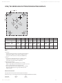
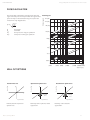
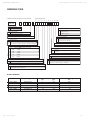
G761/761 SERIES HOLE PATTERN FOR MOUNTING SURFACE
X
F2
F1
P
G
Y
X
A
B
T
F3
F4
Designation
P
A
B
T
X
G
F1
F2
F3
F4
Size Ø
mm
in
8.15
0.321 8.15
0.321
8.15
0.321
8.15
0.321
5.00
0.197
3.45 M8
M8
M8
M8
0.136 5/16-18 5/16-18 5/16-18 5/16-18
Position X
mm
in
22.23
0.875
11.11
0.438
33.34
1.313
22.23
0.875
33.32
1.312
12.32 0
0.485 0
44.45
1.750
44.45
1.750
0
0
Position Y
mm
in
21.42
0.844 32.54
1.281
32.54
1.281
43.64
1.718
8.74
0.344
19.84 0
0.781 0
0
0
65.07
2.562
65.07
2.562
Notes
1. Surface:
Surface to which the valve is mounted requires flatness
of 0.025 mm (0.001 in) over 100 mm (3.94 in) and an
average finish Ra better than 0.8 µm (0.000032 in).
2. Ports:
For maximum flow the ports P, T, A, and B must be
designed with diameters of 8.2 mm (0.320 in), port X with diameter of 5.0 mm (0.20 in)
3. Recommended Seals:
85 durometer 1.78 mm (0.070 in) cross section,
10.82 mm (0.426 in) inside diameter O-ring for P, T, A and
B ports compatible with the hydraulic fluid.
Port X 85 durometer 1.78 mm (0.070 in) cross section,
9.25 mm (0.364 in) ID, O-ring compatible with the
hydraulic fluid.
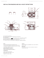
Conversion Instruction
For operation with internal or external pilot connection.
Pilot flow supply Screw and seal washer location (M4 X 6 DIN EN ISO 4762)
X
P
Internal P
closed
open
External X
open
closed
Rev. H, January, 2014
10