1
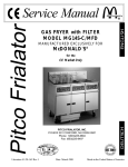
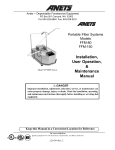
Pitco Frialator
Service Manual
Literature # L20-157 Rev 2
GAS FRYER
with
FILTER
Model Number
AG14S
PITCO FRIALATOR, INC.
P.O.BOX 501 CONCORD, NH 03302-0501
Phone: 1(603)225-6684
Toll Free: 1(800)258-3708
Fax: 1(603)225-8497
Rev Date 29 April 1997
Made in the United States of America
FOR YOUR SAFETY:
Do not store gasoline or other flammable
vapors or liquids in the vicinity of this or
any other appliance.
TO THE PURCHASER
POST IN A PROMINENT LOCATION INSTRUCTIONS TO BE FOLLOWED IN THE
EVENT THAT AN OPERATOR SMELLS GAS.
OBTAIN THIS INFORMATION FROM YOUR
LOCAL GAS SUPPLIER.
WARNING:
IMPROPER INSTALLATION, ADJUSTMENT,
ALTERATION, SERVICE OR MAINTENANCE
CAN CAUSE PROPERTY DAMAGE, INJURY
OR DEATH. READ THE INSTALLATION, OPERATING AND MAINTENANCE MANUALS
THOROUGHLY BEFORE INSTALLING OR
SERVICING THIS EQUIPMENT.
can give off a dangerous carbon monoxide gas. Carbon
Monoxide is a clear odorless gas that can cause suffocation.
WARNING
Carbon Monoxide gas can build up if you obstruct the
flue. Blocking the flue will also cause the unit to overheat. DO NOT obstruct the flow of combustion/ventilation or air opening around the machine. Ensure that
you meet the minimum clearances specified in the installation instructions. Adequate clearance around the
unit is necessary for servicing and proper burner operation.
WARNING
If the machine should shut down unexpectedly wait 5
minutes before attempting to restart it. This will allow
time for any excess gas in the unit to dissipate.
WARNING
The power supply must be disconnected before servicing or cleaning the unit.
WARNING
This appliance is equipped with a grounding plug. This
is for your protection against shock hazard in the event
of equipment malfunction. Always plug the unit into a
properly grounded receptacle. DO NOT cut or remove
the grounding prong.
WARNING
DO NOT supply the fryer with a gas that is not identified on the data plate, located on the inside of one of
the doors of the machine. If you need to convert the
machine to another type of fuel, contact your dealer or
Authorized Pitco Service Agency.
WARNING
DO NOT use an open flame to check for gas leaks!
Keep all open flames away from the machine at all
times.
WARNING
If your Pitco Frialator fryer is equipped with a Gas Hose,
Quick Disconnect and restraining device, when the fryer
is in its operating location, lock the casters and reattach
the restraining device to the rear of the machine.
WARNING
Machines equipped with casters and a flexible power
cord, must be connected to a gas supply with a QuickDisconnect device. This quick disconnect must comply with ANSI Z24.41. To limit the movement of the
unit without depending on the connector or quick disconnect, a restraining device must also be installed.
WARNING
There is an open flame inside the machine. The unit
may get hot enough to set nearby materials on fire. Keep
the area around the unit free from combustibles.
WARNING
Ensure that the machine can get enough air to keep the
flame burning correctly. If the flame is starved of air it
WARNING
Shortening, when it is at cooking temperatures, is very
HOT and DANGEROUS! Use extreme caution when
handling! Use the proper protective gear such as insulated gloves, aprons, face shield and sleeves when handling hot shortening. DO NOT attempt to move any
machine that has hot oil in it. Allow the oil to cool to
room temperature or drain the oil into a suitable container before moving the fryer.
Retain this manual for future reference.
ORIGINAL EQUIPMENT LIMITED WARRANTY - ADVANCED FRYERS
General Warranty
Pitco Frialator, Inc. warrants to the original user of its Advanced Fryer cooking appliance that said appliances and related equipment will be free
from defects in material and workmanship under normal use for a period of one (1) year from the date of installation, with appropriate documentation,
subject to the following additions, exceptions, exclusions and limitations.
What is covered
This warranty is limited to the repair or replacement at the Company’s option, without charge, of any part found to be defective within the warranty
period and reasonable expenses incurred for freight and material for the installation of such part; in addition, the Company’s obligation shall be limited to
reimbursement for normal labor on such parts.
Pitco Frialator, Inc. agrees to pay the G.S. Blodgett Corporation Authorized Service and Parts Distributor, for any labor and material required to
repair or replace, at the Company’s option, any part which may fail due to defects in material or workmanship during the above general warranty period.
Fry Tanks
In addition, the Company warrants to the original user of any fry tank to be free from defects for a period of ten (10) years from the date of
manufacture. Labor and freight shall be the responsibility of the user. This shall only obligate the Company to repair or replace, at its option, any fry tank
which it determines to be defective. Claims under this item shall be supported by a statement detailing the defect, and the Company may require the return
of the fry tank claimed to be defective.
Computer or Digital Cooking Controller
In addition, the Company warrants to the original user of any Cooking Computer or Digital Controller to be free from defects for a period of two (2)
years,from the date of manufacture. During the two (2) year period all charges involved in the replacement of a Pitco Computer or Digital Controller will
be the responsibility of Pitco Frialator Inc.
Burner
In addition, Company warrants to the original user of any Advanced Fryer Burner to be free from defects for a period of five (5) years from the date
of manufacture. Labor and freight shall be the responsibility of the user.
How to Keep Your Warranty in Force
€
Make sure any shipping damages are reported immediately. Damages of this nature are the responsibility of the carrier.
€
Install the unit properly. This is the responsibility of the installer and the procedures are outlined in the manual. Do not install it in a home
or residence.
€
Maintain the unit properly. This is the responsibility of the user, the procedures are outlined in the manual.
What is NOT covered under this Warranty
€
Adjustments, such as calibration, leveling, tightening of fasteners or plumbing or electrical connections normally associated with initial
installation are not covered under this warranty. These procedures are outlined in the installation manual.
€
Damaged due to flood, fire or other acts of Nature are not covered under this warranty.
€
If the unit is used for a purpose other than for which it was intended or designed, resulting damages are not covered under the warranty.
€
Failures due to erratic voltage or gas supplies are not covered under the warranty.
€
Material alterations or modifications from the condition in which the unit left the factory are not covered under the warranty.
€
Units with unreadable, obliterated or removed serial number rating plates are not covered by the warranty.
€
Any parts other than Genuine OEM parts from Pitco Frialator, Inc. or its Authorized Parts and Service Distributors are not covered by the
warranty.
€
Any other failure which is not attributable to a defect in materials or workmanship is not covered bt the warranty.
This warranty specifically excludes parts which wear or would be replaced under normal usage, including, but not limited to, electric lamps, fuses,
interior or exterior finishes and gaskets.
Limits to the Warranty
Outside the United States of America and Canada, this warranty is limited to the replacement of parts and Pitco Frialator, Inc. will not bear any other
expense be it labor, mileage, freight or travel.
Charges for mileage over one hundred (100) miles, travel time over two (2) hours, overtime, and holiday charges are not covered under this warranty.
These charges are the responsibility of the individual or firm requesting these services.
If any oral statements have been made regarding the appliance, these statements do not constitute warranties and are not part of the contract of sale.
This limited warranty constitutes the complete, final and exclusive statement with regard to warranties.
THIS LIMITED WARRANTY IS EXCLUSIVE AND IS IN LIEU OF ALL OTHER WARRANTIES WHETHER WRITTEN, ORAL OR IMPLIED, INCLUDING, BUT NOT LIMITED TO ANY WARRANTY OF MERCHANTABILITY OR FITNESS FOR A PARTICULAR PURPOSE OR
WARRANTY AGAINST LATENT DEFECTS.
Limitations of Liability
In the event of a warranty or other claim, the sole obligation of Pitco Frialator, Inc. will be the repair or replacement, at the Company’s option, of the
appliance or the component part. This repair or replacement will be at the expense of Pitco Frialator, Inc. except as limited by this warranty statement. Any
repair or replacement under this warranty does not constitute an extension in time to the original warranty. Parts covered under this warranty will be
repaired or replaced, at the Company’s option, with new or functionally operative parts. The liability of Pitco Frialator, Inc. on any claim of any kind,
including claims based on warranty, express or implied contract, negligence, strict liability or any other legal theories will be exclusively the repair or
replacement of the appliance. This liability will not include, and the purchaser specifically renounces any right to recover special, incidental, consequential or other damages of any kind, including, but not limited to, injuries to persons, damage to property, loss of profits or anticipated loss of the use of this
appliance.
If any provision of this warranty is unenforceable under the law of any jurisdiction, that provision only will be inapplicable there, and the remainder
of the warranty will remain unaffected. The maximum exclusion or limitation allowed by law will be substituted for the unenforceable provision.
How to Obtain Warranty Service
First direct your claim to the G.S. Blodgett Corporation Authorized Service and Parts Distributor closest to you giving complete model, serial and
code numbers, voltage, gas type, and description of the problem. Proof of the date of installation and/or the sales slip may also be required. If this
procedure fails to be satisfactory, write the National Service Manager, Pitco Frialator, Inc., P. O. Box 501, Concord, NH. 03302-0501. USA
This warranty gives you certain specific legal rights; you may have other rights which vary from state to state.
i
ii
Table of Contents
WARRANTY STATEMENT ................................................................................................ i
TABLE OF CONTENTS ...................................................................................................... iii
INSTALLATION INSTRUCTIONS..................................................................................... 1
Ventilation ...................................................................................................................... 1
Quick Disconnect Gas Connection ................................................................................ 1
Fuel Supply Line Leak and Pressure Testing ................................................................. 1
Clearances ...................................................................................................................... 1
Leveling the fryers.......................................................................................................... 1
Filling the fryer with oil ................................................................................................. 2
HOW DOES IT WORK? ...................................................................................................... 3
Heating System ............................................................................................................... 3
Hi - Limit System ........................................................................................................... 3
Filter System................................................................................................................... 3
LADDER DIAGRAMS ........................................................................................................ 4
COMPONENT TROUBLESHOOTING .............................................................................. 5
Probe ............................................................................................................................... 5
Relays ............................................................................................................................. 5
Hi Limits......................................................................................................................... 5
Drain Valve & Return Valve Switches ........................................................................... 5
Transformer .................................................................................................................... 6
Blower ............................................................................................................................ 6
Pressure Switch .............................................................................................................. 6
Gas Valve ........................................................................................................................ 6
Ignition Control Module ................................................................................................. 6
TROUBLESHOOTING GUIDE .......................................................................................... 7
Fryers .............................................................................................................................. 7
Filters .............................................................................................................................. 8
COMPONENT CHANGEOUT ............................................................................................ 9
Probes ............................................................................................................................. 9
Hi Limits......................................................................................................................... 9
Computers ...................................................................................................................... 9
Components mounted in the front panel ........................................................................ 10
Filter Relays ................................................................................................................... 10
Control Relays ................................................................................................................ 10
Circuit Breaker ............................................................................................................... 10
Gas Valves ...................................................................................................................... 11
Burners and Spark Ignitors ............................................................................................. 11
Proximity Switches......................................................................................................... 11
Blowers ........................................................................................................................... 12
Pressure Switches ........................................................................................................... 12
Fry Tanks ........................................................................................................................ 13
Parts ...................................................................................................................................... 15
Operational Components ................................................................................................ 15
Filter ............................................................................................................................... 15
Miscellaneous ................................................................................................................. 15
Wiring Harnesses ........................................................................................................... 16
Parts Identification ................................................................................................................ 17
Schematics ............................................................................................................................ 18
iii
iv
INSTALLATION INSTRUCTIONS
Note: It is recommended that the ventilation
system be cleaned and maintained on a regular basis.
CAUTION:
This equipment is manufactured for the use
on a particular type of gas and electrical voltage which is specified on the rating plate located on the inside of the door.
Quick Disconnect Gas Connection:
Units equipped with casters must be installed
with connectors that comply with the standards
for connectors for Movable Gas Appliances,
ANSI Z21.69-1987, and Addenda Z21.69A1989. (CAN/CGA - 6.16 and CAN/CGA - 6.9.)
This connection should include a quick disconnect device that complies with the Standard for
Quick Disconnect Devices for use with Gas Fuel,
ANSI Z21.41-1989. When installing a quick disconnect you must also install a means of limiting the
movement of the fryer. This device will prevent the
gas line or quick disconnect from being strained.
When your fryers arrive, look them over carefully noting any damage on the freight bill. If concealed damage is found after you have accepted
the equipment, report it to the carrier immediately, as all claims must be filled within 15 days
of the receipt of the shipment. Also, be sure to
keep any packing materials as these will be necessary to make a claim.
Follow these installation instructions carefully.
A proper installation is important for the operaFuel Supply Line Leak and Pressure Testing:
tion of the fryers.
In the United States, all installations must conform to all local and state codes and well as the
National Fuel Gas Code (ANSI 223.1 1992). In
Canada, installations must be made in accordance to Canadian Standard CAN 1-B149.1 or
.2 “Installation Codes for Gas Burning Appliances & Equipment.”
The fuel supply system must be tested before the machine can be used. If the fuel line is going to be tested
at a pressure greater than (>) 1/2 PSI (3.45 kPa), make
sure that the unit is disconnected from the fuel line.
If the fuel line is going to be tested at a pressure
equal to or less than (≤) 1/2 PSI (3.45 kPa), the machine can be connected to the supply but the gas valve
must be shut.
Electrically operated appliances must be electrically grounded in accordance with local codes;
or in the absence of local codes, with the National Electric Code ANSI/NFPA No. 70-1996;
in CANADA, with CSA C22-1 Canadian Electrical Code Part 1.
Clearances:
Minimum clearance of 6" (15cm) must be maintained from combustible construction on each
side and the rear of the equipment. This equipment may be installed on combustible floors.
Maintain a minimum of 24" (61cm) clearance in
front of the fryer to provide for proper operation,
maintenance and servicing.
Ventilation:
A proper ventilation system is also an important part of the installation. For information on
the construction and installation of ventilating
hoods, please see “Standard for the Installation of Equipment for the Removal of Smoke
and Grease Laden Vapors from Commercial
Cooking Equipment”, N.F.P.A. No. 96-1987.
Copies can be obtained by writing to the National Fire Protection Association, Battery March
Park, Quincy, MA 02269.
NOTE: Do not block the area around the bottom or underneath the fryer. The air required to
support the gas combustion is drawn from the
underneath and sides of the fryer.
Leveling the fryers:
Leveling the fryers will help ensure proper opera1
tion. To level the fryers loosen the two set screws on
the caster/leg stem. Rotate the collar of the caster/
leg to raise or lower the height of the unit. Tighten
the set screws to lock the adjustment in place.
Filling the fryer with oil:
CAUTION:
Never operate this equipment empty. Always
make sure there is the correct amount of shortening or in the case of cleaning, water in the
fry tank before turning the unit ON.
It is very important to make sure the oil level is correct before attempting to heat shortening in your Pitco
fryer.
Liquid shortening can be poured directly into the fry
tank until the correct level has been reached. This is
indicated by a line on the right or left hand sides of
the inside of the fry tank. "C" is the level for Cold
shortening and "H" is the level for Hot shortening.
For solid shortening, the shortening must be cut
into small blocks about 1" (2.54 Cm) in size.
These small blocks must be placed under and
around the heat tubes.
Regular cleaning of this equipment, as well as
the hood, is an important part of proper maintenance. Clean the fry tanks using the Boil Out
procedure described in the operating manual.
A wiring diagram is located in the back of this
manual and inside the fryers.
Retain this manual for future reference.
2
contacts within the Heat Demand Relay. Since the
Heat Demand Relay is now closed the Ignition Control Module and Hi Limit Switch will receive 24
VAC. If the Hi Limit Switch is NOT tripped it will
allow 24 VAC to be supplied to the Pilot Solenoid of
the Gas Valve. The Ignition Control Module supplies 24VAC to the Main Solenoid of the Gas valve.
The Ignition Control Module alternately sends a
spark signal to the Ignitor and tests for a flame sense
signal from the same Ignitor. When a flame sense
signal is received it will cease to send the spark signal and continue to sense flame. If, after 10 seconds,
a flame sense signal has not been established the Ignition Control Module will "Lock Out" and cease to
run until it re-energizes.
HOW DOES IT WORK?
The Advanced Gas Fryer will have certain reactions to what is happening, knowing what
these reactions are and knowing what the machine is trying to do will enable us to diagnose
most of the problems likely to be encountered.
Heating System
• Power to the machine is turned ON.
• The computer is supplied with 24VAC and, if
the Drain Valve Handle is closed, the Proximity
Switch will supply 24 VAC to the DVI (Drain Valve
Interlock) Input at the computer. As soon as the computer is powered up it will show something on the
display.
• Computer calls for heat.
• Full Tank - The Heat Demand Relay will energize, supplying the Blower, the Pilot Solenoid on the
Gas Valve and the Ignition Control Modules with
power. Both Ignition Control Modules supply power
to the Spark Ignitors. At the same time one of the
Ignition Control Modules supplies power to the Gas
Cut Off Relay. The Gas Cut Off Relay energizes allowing the second Ignition Control Module to supply power to the normally open Pressure Switch.
When the Blower comes up to speed, which should
take a couple of seconds, the Pressure Switch will
close allowing 24 VAC to the Main Solenoid of the
Gas Valve. This will also supply the computer with
a heat feedback signal. Since there are two burners
in a full vat machine each of the Ignition Control
Modules alternately sends a spark signal to the Ignitor and tests for a flame sense signal from the same
Ignitor. When a flame sense signal is received it will
cease to send the spark signal and continue to sense
flame. If, after 10 seconds, a flame sense signal has
not been established the Ignition Control Module will
"Lock Out" and cease to run until reenergized.
• Split Vat - The same power that supplies the computer also supplies 24 VAC to the normally open
Pressure Switch. When the computer energizes the
Heat Demand Relay the Blower will be supplied with
power and come up to speed. At this time the air
pressure from the blower will close the Pressure
Switch and allow 24 VAC to go to the second set of
Hi - Limit System:
When the Hi Limit trips it causes the power to
the Pilot Solenoid to stop and gas will cease to
flow through the gas valve. This will cause a
Lock Out condition and the burners will not light.
The Hi Limit Switch should be manually reset by
pressing the Power Switch to the OFF position and
pressing it back to the ON position.
Filter System:
With the Filter Circuit Breaker in the ON position,
opening the RED Return Valve Handle will cause
the Pump On Relay to be energized and the pump
will begin to operate. Closing the Return Valve
Handle will de-energize the Relay and the Pump will
stop running.
Heat Tape:
All Advanced fryers are equipped with Heat Tape
which has an indicator light that will illuminate when
the piping is up to operating temperature, do not attempt to pump unless the Filter Ready Light has illuminated.
3
LADDER DIAGRAMS
Full Vat Fryers:
Split Vat Fryers:
4
plied to the coil. When energizing, the relay Switching Contacts will close, thus connecting the Common and Normally Open terminals.
COMPONENT TROUBLESHOOTING
Temperature Probe:
The resistance of the probe decreases as the temperature rises. The lower the temperature the greater
the resistance change will be per degree of temperature change, as the temperature approaches the working range of the probe, the resistance change will
slow and become more linear. If the probe is suspect, check its resistance and the oil/air temperature
at which it was taken. Compare these values on the
chart below.
TEMP
ºF
60°
80°
100°
120°
140°
160°
180°
200°
210°
220°
240°
260°
280°
300°
320°
325°
RESISTANCE
Ohms Ω
139055 Ω
84644 Ω
53146 Ω
34328 Ω
22755 Ω
15446 Ω
10716 Ω
7586 Ω
6427 Ω
5470 Ω
4013 Ω
2991 Ω
2262 Ω
1734 Ω
1347 Ω
1267 Ω
TEMP
ºF
330°
335°
340°
345°
350°
355°
360°
365°
370°
375°
380°
385°
390°
395°
400°
Hi Limits:
A Hi - Limit switch is a normally closed switch until
the temperature at its probe reaches 435ºF ± 15°
(225ºC ± 15º). In order to test this switch it will be
necessary to bypass the Heat Demand Relay.
This will cause the fryer to heat until the temperature of the oil reaches the necessary temperature to trip the Hi Limit.
RESISTANCE
WARNING
Do NOT leave the machine during this test. This
test will cause the oil to heat past the normal operating temperature and can cause damage to the
machine and its operator. Always use an external
temperature probe to observe the oil tempersature
during this procedure
Ohms Ω
1192 Ω
1123 Ω
1058 Ω
998 Ω
942 Ω
890 Ω
841 Ω
795 Ω
752 Ω
712 Ω
675 Ω
640 Ω
607 Ω
576 Ω
547 Ω
In order to cause the oil to reach a temperature where
the Hi Limit will trip it will be necessary to bypass
the Heat Demand Relay. To do this, use a small
jumper wire and join the Normally Open (Terminal
#5) and Common (Terminal #3) terminals on the
switch section of the relay
If the switch does not trip between the prescribed
limits it is defective and should be replaced. Once
tripped, the switch cannot be reset until the oil
has cooled to approximately 400°F (204ºC). If
If the probe returns an open circuit or 0 Ohms read- the switch cannot be reset it is defective.
ing it should be replaced. If the resistance varies more
than 20 Ohms from the above chart when being Drain Valve & Return Valve Switches:
checked between 325-375°F (162ºC - 190ºC) the
probe will give a false temperature reading on the These switches are magnetically operated Reed
computer and should be replaced. However, it will switches. When the Drain Valve handle is moved to
continue to operate at a slightly higher or lower tem- the open position, the Actuator will move away from
perature. Allow the oil to cool and check the probe the switch causing the Reed switch to open. When
resistance at a lower temperature. As can be seen the Drain Valve is closed the Reed switch will close.
from the chart a greater degree of offset can be al- This switch can also be checked with an Ohm meter.
lowed at a lower temperature.
The normal gap between the Actuator and the Sensor switch on the Drain Valve handle is 1/8" - 1/4" (3 Relays:
6 mm).
Relays will energize when the correct voltage is sup5
Transformer:
Ignitors:
Transformers are multiple input voltage, 24 volt out- When an Ignitor is supplied with power and does
put voltage and can be checked by reading the input NOT spark the Spark Gap should be checked.The
and output voltages.
distance between the Ignitor and the Ground post
should be approximately 1/8" ± 1/32".
Blower:
Check the voltage between the wires going to the
Blower. If 120 VAC is found and the Blower is NOT
turning it is defective.
Pressure Switch:
As the blower speed rises the amount of vacuum on
the suction side of the pressure switch rises past approximately 1.3" WC (0.325 kPa) the Presssure
Switch will close. When the vacuum falls below approximately 0.8" WC (0.2 kPa) the Pressure Switch
will open. With the Blower running, check the IN
and OUT voltage of the Switch. If 24VAC can be
found on one side but NOT the other the Pressure
Switch is defective.
If the Ignitor is sparking but the Burner does not light,
check for a gas supply and make sure the Ignitor is
located in the correct position as shown in the drawing.
Gas Valve:
The Knob should be in the ON position. Check for
24VAC between the terminals marked MV and MV/
PV and between PV and MV/PV. If voltage IS found
between both of these connections and the Gas Valve
does not open the Gas Valve is defective. If voltage
is NOT present at both of the coils on the Gas Valve,
troubleshoot and repair the machine until voltage IS
present at both coils, retest the Gas Valve as previously described.
Ignition Control Modules:
When the Ignition Control Module is supplied with
24 VAC from the temperature control system at the
TH terminal it will send a signal to the Ignitor which
will begin to spark. At the same time the Ignition
Control Module will also have a 24 VAC output signal on the MV terminal. The Ignition Control Module will cause the Ignitor to spark for 10 seconds and
and then look for a flame sense signal, if it does not
receive a flame sense within 10 seconds signal it will
"Lock Out".
6
TROUBLESHOOTING GUIDE
Fryers:
It is assumed that, before starting any troubleshooting, the power is turned on and the gas lines are connected correctly.
PROBLEM
PROBABLE CAUSE
CORRECTIVE ACTION
Computer does not come on
nothing shows in either display
A.
B.
C.
D.
A. Press switch to the ON position.
B. Locate the correct circuit breaker and
turn OFF and back ON again.
C. Check and Replace as needed
D. Check Transformer
Computer heat light comes on
but burners do not
A
If the oil is hot the Hi Limit may be
tripped
B. Ignition Lockout
A. Allow the oil to cool, the Hi Limit will
reset itself. Turn the computer OFF and
back ON again to reset the computer.
B. Check gas supply, Flame Sensor,
Hi Limit, Gas Valve, Ignition Control
Module/s, Pressure Switch (Full Tank),
Gas Cut Off Relay (Full Tank), Blower
(Full Tank)
No Spark heard, blower IS
running
A. Heat Demand Relay
B. Ignition Control Module
C. Spark Ignitor
A. Check and replace where needed.
B. Check and replace where needed.
C. Check / adjust / replace where needed.
Spark sound can be heard,
Blower NOT running
A. F2 fuse blown
B. Blower
C. Heat Demand Relay
A. Check and replace where needed.
B. Check and replace where needed.
C. Check and replace where needed.
Spark sound can be heard,
Blower IS running but main
burners do not run
A.
B.
C.
D.
E.
A.
B.
C.
D.
E.
Burner comes ON for short
time, does not come back on
A. Flame Sensor
B. Ignition Control Module
C. Gas Valve
Power Switch is NOT turned ON
Main circuit breaker is turned off
Fryer fuse is blown
Transformer
Ignition Control Module
Gas Valve Relay (Full Tank Only)
Defective Pressure Switch
Tripped or defective Hi limit
Gas Valve
7
Check and replace where needed.
Check and replace where needed.
Check and replace where needed.
Check and replace where needed.
Check and replace where needed.
A. Check / adjust / replace where needed.
B. Check and replace where needed.
C. Check and replace where needed.
Filters:
PROBLEM
PROBABLE CAUSE
CORRECTIVE ACTION
Red Return Valve is open but no
pump sound can be heard
A. Red Return Valve NOT fully open
B. Filter Circuit Breaker may be tripped
C. Filter Motor Thermal Overload may
be tripped
D. Sensor switch may be loose or bad
A. Pull slightly on the Red handle to check
that it is fully open.
B. Locate the circuit breaker and reset.
C. Push Red reset button located on end of
filter motor.
D. Check that the switch is tight in its
mounting. If switch is bad replace it.
Drain valve is closed and the
computer has been reset but
still shows "DRAINING" or
"TURN OFF"
A. Green Drain Valve is NOT fully
Closed
B. Sensor switch may be loose or bad
A. Apply a little more pressure to the
Green Handle to check that it is
fully closed.
B. Check that the switch is tight in its
mounting. If switch is bad replace it.
Drain Valve is OPEN, the oil
is draining slowly or not at all.
A. Green Drain Valve is NOT fully open
B. Drain is plugged with debris
A. Apply a little more pressure to the
Green Handle to check that it is fully
closed.
B. Use the Clean Out Rod from inside the
Fry Vat to clear the Drain Valve. If this
NOT clear the blockage, CLOSE the
Green Drain Valve and follow these
instructions for clearing the main drain
line.
CAUTION:
Some HOT oil may still come out when
the cap is removed.
Remove the two screw from the end
cap (Do NOT lose these.) Use the
Clean Out Rod to clear the main drain
tube. Install the end cap along with its
gasket and two screws. Do not
overtighten these screws.
8
Computers:
COMPONENT CHANGEOUT
CAUTION:
Take care not to drop any of the components from
the front panel as this will damage them.
It is assumed that for all (except where noted) of these
component changeout instructions the fryer has been
shut down and disconnected from the power and gas
supplies, cooled and drained of oil.
1. Remove the two screws from the upper mount
of the front panel.
Probes:
1. Unplug the wiring connector.
2. Unscrew the small nut on the probe seal.
3. Slide the probe from the seal.
2. Unplug the wiring connection at the rear of the
computer.
Install in the reverse order using the new ferrule NOTE: On split tank machines you will find 2 wirsupplied with the new probe.
ing connections to unplug.
Hi Limits:
1. Unplug the wiring connector.
2. Unscrew the Hi Limit from the front of the fry
tank.
Install in the reverse order.
Install in the reverse order.
9
Components mounted in the front panel:
To access all of the components mounted in the front
panel follow the instructions below:
1. Remove the computer as described previously.
The components within the front panel area can
now be accessed.
Filter Relays:
This relay is wired in the following manner -
Filter Pumps:
1. From the front of the machine, pull the ring back
on each of the 2 quick disconnects and release
the couplings.
2. Remove the 2 screws, and the front of the Pump/
Motor assembly will drop. The assembly can be
removed from the machine by lifting the rear
slightly and pushing back. The front of the mount
can be lowered until the assembly can be removed from the machine.
Control Relays:
Install in the reverse order.
Circuit Breaker:
1. Remove the 2 mounting
screws on either side of
the door magnet catch.
Remove the door magnet
catch.
2. Remove the 2 mounting
Control relays are always wired in the following manscrews from the top and
ner bottom of the cover.
3. Depress the 4 catches that
hold the circuit breaker in the cover.
10
1. Unscrew the fitting for the gas supply tubing on
the bottom of the burner.
2. Unplug the wire to the spark ignitor.
3. Remove the 2 screws that hold the spark ignitor
and burner in place.
Install of the reverse order.
Gas Valves:
1. Unscrew the fittings to the gas outlet tubes at the
top of the gas valve.
The burner and spark ignitor may be removed together. Install in the reverse order.
2. Unscrew the pipe union, located behind the gas
valve.
Proximity Switches:
3. Unplug the 3 wires that plug into the gas valve.
1. The actuator can be removed by removing the 2
mounting screws.
Install in the reverse order.
Burners and Spark Ignitors:
NOTE: If the ignitor is to be removed without the
burner start the proceedure at step 2.
11
NOTE: The new blower will be shipped with the
blower housing attached. Remove the motor from
the blower housing in the above manner. Clean the
sealant from the new motor and the old housing (still
attached to the machine). Apply a small amount of
high temperature silicone sealant to the motor mounting flange.
Install the motor in the reverse order of removal.
Pressure Switches:
1. Unscrew the plastic fitting from the air connection on the pressure switch.
2. Unplug the 2 wires from the switch.
2. The sensor may be removed by disconnecting
the wiring harness and by removing the 2 mounting screws.
Install in the reverse order.
Blowers:
1. Unplug the wiring connector.
2. Remove the 3 screws from the mounting flange.
3. Remove the 2 screws from the mounting bracket.
Install in the reverse order.
Fry Tanks:
Full Fry Tanks1. Remove ALL of the computer/controllers from
the machine.
2. Remove the burners and ignitors from the tank
to be removed.
3. Disconnect the drain valve switch wires.
4. Disconnect the return valve switch wires.
5. Disconnect the blower wires.
6. Remove the drain line from the left and right ends
of the drain valve tee.
3. Using a flat screwdriver, break the seal at the 7. Disconnect the filter return piping at the rear of
motor flange.
the Fry Tank.
4. The motor can now be lowered out of the ma- 8. Remove the 3 screws from the front of each unit.
chine.
12
12. Remove the brackets located inside the splash
back.
9. Remove all of the nuts and washers holding the
splash deck in place.
10. Remove the front deck from the machine.
13. Remove the upper rear cover.
11. Remove all of the screws holding the front of
the tank.
14. Remove the complete splash back assembly.
13
NOTE: To disconnect the filter return piping (as in
step # 15) unscrew the union connecting the return
piping to the tanks.
Install in the reverse order.
15. Remove the lower rear back cover.
16. Unscrew the compression fitting at the rear of
the tank.
17. Remove the air tube from the air box (the blower
is mounted to this box).
18. Grasp the tank by the middle tube and remove it
from the rear of the cabinet.
Split Fry TanksSplit Fry Tanks should be removed and installed as
pairs in the same manner as Full Fry Tanks. There
are 3 sets of clamps that hold the two Split Fry Tanks
together:
1. On the rear of the tank.
2. On the bottom of the tank accessed by first removing the blower.
3. On the bottom of the tank at the front.
14
Parts
Operational Components:
Part
Number
Filter:
PP11254
PP11286
PP11144
PP11067
PP11131
PP11065
PP11140
PP11141
PP11064
PP11068
PP11068
PP11033
PP10210
PP11066
PP10262
PP10263
P5045717
P5045720
PP11042
Schematic
Nomenclature
Description
A1
A1
A2/A3
M1
Computer
Computer
Ignition Control Module
Blower
Ignitor/Flame Sensor
Probe
Gas Valve, NAT
Gas Valve, LP
Hi Limit
Relay, Heat Demand
Relay, Gas Valve
Relay, Hood System
Transformer
Pressure switch
Proximity Switch, Sensor
Proximity Switch, Actuator
Fuse, 2 Amp Slow Blow
Fuse, 4 Amp Slow Blow
Power Cord
RT1
V1
V1
S2
K1
K2
K3
T1
S4
S3
S3
F1
F2
A7001701
B4002001
B4002002
P6071780
PP11181
PP11182
A7004401
A6643701
Part Number Description
PP10101
PP10416
PP10417
PP10262
PP10263
PP10058
PP10460
PP11138
PP11172
PP10032
B6641101
B6640801
B6641001
A7013502
P6071516
B6640901
A7001202
PP10409
Motor
Motor Only
Pump Only
Proximity Switch, Sensor
Proximity Switch, Actuator
Relay, Filter
Circuit Breaker
Gasket, Drain Line End
Clamp, Band
Gasket
Filter Pan Assembly
Filter Drawer Assembly
Lid, filter (Front)
Lid, filter (Rear)
Handle, Lid
Retainer, Paper
Support, Paper
O-Ring
Bracket, Drawer Roller Mount
Handle, Return Valve LH
Handle, Return Valve RH
Valve, Ball 3/8"
Gasket, Drain End
Gasket, Tee Clean Out
Cover, Tee Clean Out
Thumb Screw
Miscellaneous:
Call Factory
Call Factory
Call Factory
B1003001
B3502301
PP10814
PP
Part Number
15
Tank, Full Tank
Tank - LT Split Tank, w/ Gaskets
Tank - RT Split Tank, w/ Gaskets
Baffle, Heat Tube
Flue
Caster, 9" Non Lock
Caster, 9" Locking
Description
B2302301
B2302302
A3802901
A3802903
B3801301
PP11006
P6071305
PP10368
P6071769
A1401202
PP11130
B4001601
B4001701
B4001702
A4015801
PP11059
PP11132
PP11170
B2100904
B2100901
P6071516
A8022301
A8022303
P6073148
B4510401
Door, LH
Door, RH
Hinge, Top
Hinge, Bottom
Hinge Rod
Handle, Door
Magnet Catch
Drain Valve, Full Tank
Drain Valve, Split Tank
Clamp, Hi Limit Bulb
Burner, Main
Handle, Drain Valve, Full Tank
Handle, Drain Valve, Split Tank LH
Handle, Drain Valve, Split Tank RH
Handle, Lever Stop Release
Plunger
Orifice, #31 Nat Gas
Orifice, #49 LP Gas
Cover, Full Tank
Cover, Split Tank
Handle, cover
Bracket, LH Ignitor
Bracket, RH Ignitor
Rack Tube, Full Vat
Rack Tube, Split Vat
Wiring Harnesses:
B6728001
B6730801
B6730701
B6731101
B6731201
PP11128
Harness, Filter Pump
Harness, Full Tank
Harness, Split Tank
Harness, Control Cable
Harness, Filter Option
Wire, Ignitor
16
Parts Identification
Computer/Controller
PP11254
Proximity switch, Sensor
PP10262
Ignition Control Module
PP11144
Proximity Switch, Actuator
PP10263
Blower
PP11067
Motor, Filter
PP10101
Ignitor/Flame sensor
PP11131
Relay, Filter
PP10058
Probe
PP11065
Circuit Breaker
PP10460
Gas Valve
PP11140 - Nat Gas
PP11141 - LP
Gasket, Clean Out Port
PP11182
Hi Limit Switch
PP11064
Gasket, Drain Line
PP10032
Relay, Heat Demand & Gas Valve
PP11068
Clamp, Band
PP11172
Relay, Hood System
PP11033
Valve, Ball 3/8"
P6071780
Transformer
PP10210
Pressure Switch
PP11066
17
18
19
In the event of problems with or questions about your order, please contact the Pitco Frialator factory,
from 8:00 a.m. - 5:00 p.m., Eastern Standard Time, Monday through Friday, toll-free at:
(800)258-3708 US and Canada only or
(603)225-6684 World Wide
AG14 FRYER PARTS BREAKDOWN
1
AG14 FRYER FRONT
PARTS LISTS
I.D. #
PART #
PART DESCRIPTION
1 ...................................................... PP10752 ......................................... 10-32 X 1/2” SCREW
2 ...................................................... A1830901 ...................................... MAGNET STRIKER PLATE
........................................................ A1835001 ...................................... MAGNET STRIKER PLATE COVER
3 ...................................................... A1837501 ...................................... SWITCH MOUNTING PLATE
4 ...................................................... A3802901 ...................................... TOP RIGHT & LEFT DOOR HINGE
5 ...................................................... B3801301-C .................................. DOOR HINGE PIN
6 ...................................................... A3802903 ...................................... BOTTOM RIGHT & LEFT DOOR HINGE
7 ...................................................... B2302301-C .................................. LEFT DOOR ASSEMBLY
8 ...................................................... B2302302-C .................................. RIGHT DOOR ASSEMBLY
9 ...................................................... B3626803-C .................................. CE COMPUTER BEZLE ASSEMBLY FULL
B3626804-C .................................. CE COMPUTER BEZLE ASSEMBLY SPLIT
10 .................................................... P0092300 ....................................... 10-24 HEX NUT
11 .................................................... P0080601 ....................................... #10 FLAT WASHER
12 .................................................... PP11370 ......................................... I-12 COMPUTER (SINGLE)
PP11372 ........................................ I-12 COMPUTER (DUAL)
13 .................................................... B362601-C .................................... COMPUTER BEZLE
14 .................................................... PP11068 ......................................... HEAT DEMAND RELAY
P5046688 ....................................... MAIN GAS VALVE RELAY
15 .................................................... A5059102 ...................................... TERMINAL STRIP COVER
16 .................................................... P5045282 ....................................... WIRE TERMINAL STRIP
17 .................................................... PP11058 ......................................... FILTER PUMP RELAY
18 .................................................... PP10429 ......................................... TRANSFORMER CE
PP10210 ........................................ TRANSFORMER DOMESTIC
19 .................................................... PP11225 ......................................... SPARK IGNITION MODULE DOMESTIC
PP11145 ......................................... SPARK IGNITION MODULE CE
2
3
AG14 FRYER CABINET
PARTS LISTS
I.D. #
PART #
PART DESCRIPTION
1 ...................................................... A1834301 ...................................... DUAL FRYER CABINET COVER (STAND(For fryers without capping piece) . A1834101 ..................................... TRIPLE FRYER CABINET COVER OFF)
A1834301+ A1834301 .................. QUAD FRYER CABINET COVER
A1834301+ A1834101 .................. QUINT FRYER CABINET COVER
2 ...................................................... A4106302 ...................................... SINGLE BACK SPLASH SEAL ANGLE
(For fryers without capping piece) A4105502 ....................................... DUAL BACK SPLASH SEAL ANGLE
A4105602 ...................................... TRIPLE BACK SPLASH SEAL ANGLE
A4105702 ...................................... QUAD BACK SPLASH SEAL ANGLE
A4105802 ...................................... QUINT BACK SPLASH SEAL ANGLE
3 ...................................................... B4101601-C .................................. SINGLE FRYER BACK SPLASH
B4101001-C .................................. DUAL FRYER BACK SPLASH
B4101101-C .................................. TRIPLE FRYER BACK SPLASH
B4101201-C .................................. QUAD FRYER BACK SPLASH
B4101701-C .................................. QUINT FRYER BACK SPLASH
4 ...................................................... PP10752 ......................................... 10-32 X 1/2” SCREW
5 ...................................................... A1623901 ...................................... REAR CABINET ACCESS PLATE (STEEL)
A1623902 ...................................... REAR CABINET ACCESS PLATE (SS)
6 ...................................................... A1623501+A1623502 ................... SINGLE FRYER CABINET BACK
(1st #galvinized, 2nd # stainless)
A1623601+A1623502 ................... DUAL FRYER CABINET BACK
A1623701+A1623702 ................... TRIPLE FRYER CABINET BACK
A1623801+A1623802 ................... TRIPLE FRYER CABINET BACK TOP
USE DUAL TWICE ........................ QUAD FRYER CABINET BACK
USE DUAL & TRIPLE ................... QUINT FRYER CABINET BACK
7 ...................................................... P0020600 ....................................... 1/4” X 5/8” BOLT
8 ...................................................... PP10815 ......................................... 9” LOCKING CASTER
8 ...................................................... PP10814 ......................................... 9” NON-LOCKING CASTER
9 ...................................................... P0093300 ....................................... 1/4” X 20 NUT
10 .................................................... B3622401-C .................................. SINGLE FRONT PANEL TOP DECK
B3627001-C .................................. DUAL FRONT PANEL TOP DECK
B3627201-C .................................. TRIPLE FRONT PANEL TOP DECK
B3627401-C .................................. QUAD FRONT PANEL TOP DECK
B3628201-C .................................. QUINT FRONT PANEL TOP DECK
11 .................................................... P0080650 ....................................... 1/4” FLAT WASHER
12 .................................................... P0093300 ....................................... 1/4” X 20 NUT
13 .................................................... A1838101 ...................................... SINGLE CABINET BOTTOM PLATE
A1834501 ...................................... CABINET BOTTOM PLATE LEFT HAND
(Non-filter).......... A1839301 ...................................... DUAL CABINET BOTTOM PLATE
(Non filter) .......... A1839303 ...................................... TRIPLE CABINET BOTTOM
(Filter) ................. A1839401 ...................................... TRIPLE CABINET BOTTOM RIGHT H.
A1839501 ...................................... PUMP BOTTOM COVER
4
5
1
6
5
4
3
2
7
8
9
13
11
10
13
AG14 FRYER FILTER
PARTS LISTS
I.D. #
PART #
PART DESCRIPTION
1 ...................................................... B4003203-C .................................. OIL RETURN HANDLE FULL & RH SPLIT
B4003204-C .................................. OIL RETURN HANDLE LH SPLIT
2 ...................................................... P0079500 ....................................... 10-24 X 1/2” SCREW
3 ...................................................... A7004401 ...................................... DRAIN LINE CLEAN OUT COVER
4 ...................................................... PP11182 ......................................... CLEAN OUT COVER GASKET
5 ...................................................... PP10568 ......................................... 10-24 WING NUT
6 ...................................................... B6643101-C .................................. FILTER DRAIN LINE END CAP
7 ...................................................... PP11181 ......................................... DRAIN LINE END CAP GASKET
8 ...................................................... PP10696 ......................................... 10-24 X 1/2” SCREW
9 ...................................................... PP11241 ......................................... FLEX TUBING WITH FITTINGS 18”
10 .................................................... B6638601-C .................................. PUMP & MOTOR ASSEMBLY 115VAC
(Including tubing & heat tape) ... B6638602-C .................................. PUMP & MOTOR ASSEMBLY 240VAC
(Including tubing & heat tape) ... B6638603-C .................................. PUMP & MOTOR ASSEMBLY 220VAC
(Pump & motor only) ...... PP10101 ......................................... PUMP & MOTOR ASSEMBLY 115-230VAC
PP10416 ........................................ MOTOR ONLY 115-230VAC
(Pump & motor only) ...... PP10171 ......................................... PUMP AND MOTOR ASSEMBLY
PP10417 ........................................ PUMP ONLY
11 .................................................... PP11242 ......................................... FLEX TUBING WITH FITTINGS 20”
12 .................................................... P0020600 ....................................... 1/4-20 X 5/8 BOLT
13 .................................................... P0080650 ....................................... 1/4 FLAT WASHER
14 .................................................... B6652601-C .................................. FILTER RETURN RECEPTICLE ASSY.
15 .................................................... PP10039 ......................................... HEAT TAPE 165 WATT 110VAC 79”
PP10080 ........................................ HEAT TAPE 165 WATT 240VAC 79”
PP10194 ........................................ HEAT TAPE 96 WATT 110VAC 48”
PP10598 ........................................ HEAT TAPE 96 WATT 240VAC 48”
6
7
4
3
2
5
6
7
8
1
SEE DETAIL A
15
14
9
10
11
12
13
AG14 FRYER FILTER DRAWER
PARTS LISTS
I.D. #
PART #
PART DESCRIPTION
1 ...................................................... B6640901-C .................................. PAPER RETAINING RACK
2 ...................................................... B6647701-C .................................. OIL DRAIN CATCH TOWER
3 ...................................................... PP10409 ......................................... FILTER COUPLING “O” RING
4 ...................................................... B6661601-C .................................. FILTER PICK-UP ASSEMBLY
5 ...................................................... P0020900 ....................................... 1/4-20 HEX HEAD SCREW
P6071020 ....................................... 1/4” NYLON BUSHING
P0080650 ....................................... 1/4” FLAT WASHER
P0093300 ....................................... 1/4-20 NUT
6 ...................................................... PP10177 ......................................... VINYL PROTECTIVE COVER
P0093300 ....................................... 1/4-20 NUT
P0080650 ....................................... 1/4” FLAT WASHER
P0020900 ....................................... 1/4-20 HEX HEAD SCREW
7 ...................................................... B6640701-C .................................. FILTER DRAWER HANDLE
8 ...................................................... B6640601-C .................................. FILTER DRAWER WELDMENT
9 ...................................................... PP11152 ......................................... ROLLER WHEEL KIT
10 .................................................... B6656801-C .................................. FILTER DRAWER EXTENSION RAIL (RH)
B6656802-C .................................. FILTER DRAWER EXTENSION RAIL (LH)
11 .................................................... A7008302 ...................................... PAPER SUPPORT RACK
12 .................................................... B6661501-C .................................. FILTER PAN
13 .................................................... P0007300 ....................................... 8-32 X 1/4” SCREW
14 .................................................... PP10900 ......................................... FLAT WASHER
15 .................................................... B6641001-C .................................. FRONT FILTER PAN COVER W/HANDLE
A7001102 ...................................... FRONT FILTER PAN COVER NO HANDLE
16 .................................................... P6071516 ....................................... FILTER PAN COVER HANDLE
17 .................................................... A7013502 ...................................... REAR FILTER PAN COVER
18 .................................................... B6654101-C .................................. CRUMB CATCH BASKET
8
9
AG14 FRYER DRAIN VALVE HANDLE
PARTS ASSEMBLY
I.D. #
PART #
PART DESCRIPTION
1 ...................................................... PP11302 ......................................... VINYL DRAIN VALVE HANDLE COVER
2 ...................................................... PP10263 ......................................... DRAIN PROXIMITY SWITCH ACTUATOR
3 ...................................................... B4002902-C .................................. DRAIN VALVE HANDLE FULL, RH SPLIT
B4002901-C .................................. DRAIN VALVE HANDLE LH SPLIT VAT
4 ...................................................... PP10266 ......................................... 4-40 X 1/4” SCREW
5 ...................................................... PP10647 ......................................... 1/2-13 NUT
6 ...................................................... PP11059 ......................................... PLUNGER ASSEMBLY
7 ...................................................... A4015801 ...................................... DRAIN HANDLE RELEASE LEVER
8 ...................................................... PP11303 ......................................... RELEASE LEVER VINYL COVER
9 ...................................................... B4003001-C .................................. FULL VAT HANDLE ASSEMBLY
(Complete drain valve handle assy) B4003003-C .................................. LH SPLIT VAT HANDLE ASSEMBLY
B4003005-C .................................. RH SPLIT VAT HANDLE ASSEMBLY
10
11
AG14 GAS & BURNER SYSTEM
PARTS LISTS
I.D. #
PART #
PART DESCRIPTION
1 ...................................................... B3317701-C .................................. FULL VAT BURNER BOX ASSEMBLY
B3321101-C .................................. FULL VAT BURNER BOX INSULATION
KIT
2 ...................................................... PP11064 ......................................... HI LIMIT SWITCH
3 ...................................................... A8027301 ...................................... IGNITOR MOUNTING BRACKET
4 ...................................................... B8022301-C .................................. BURNER (DOMESTIC)
B8027001-C .................................. BURNER (CE GERMANY)(CE LP)
5 ...................................................... PP11131 ......................................... IGNITOR (DOMESTIC)
PP11193 ......................................... IGNITOR (CE)
6 ...................................................... PP11193 ......................................... FLAME SENSOR (CE)
7 ...................................................... CALL SERVICE AGENT FOR # BURNER ORIFICE
8 ...................................................... PP10958 ......................................... CE GAS VALVE (NAT)
PP11112 ......................................... CE GAS VALVE (PROPANE)
9 ...................................................... B3316801-C .................................. TEMPERATURE PROBE ASSEMBLY
10 .................................................... B3314801-C .................................. SPLIT VAT BURNER BOX ASSEMBLY LH
B3314802-C .................................. SPLIT VAT BURNER BOX ASSEMBLY RH
B3321201-C .................................. SPLIT VAT BURNER BOX INSULATION
KIT
11 .................................................... B8021602-C .................................. COMBUSTION TUBE (FULL & SPLIT
VAT)
12 .................................................... B3316601-C .................................. SPLIT VAT TANK
13 .................................................... B3316501-C .................................. FULL VAT TANK
12
13
12
1
2
3
4
5
6
7
11
10
8
9
13
AG14 FRYER ACCESSORIES
PARTS LISTS
I.D. #
PART #
PART DESCRIPTION
1 ...................................................... B2100903-C .................................. COVER ASSEMBLY (SPLIT VAT)
2 ...................................................... PP11332 ......................................... FRYER COVER HANDLE
3 ...................................................... P0082400 .......................................
4 ...................................................... PP10693 .........................................
5 ...................................................... A1103202 ....................................... BASKET HANGER
6 ...................................................... A1907504 ...................................... CHANNEL STRIP INTERIOR OF A SPLIT
A1906804 ...................................... CHANNEL STRIP (SPLIT TO SPLIT VAT)
7 ...................................................... A1906804 ...................................... CHANNEL STRIP (SPLIT TO FULL, FULL
TO FULL VAT)
8 ...................................................... P6073148 ....................................... TUBE RACK (FULL VAT)
B4510401-C .................................. TUBE RACK (SPLIT VAT)
9 ...................................................... B2100904-C .................................. COVER ASSEMBLY (FULL VAT)
14
15