1
owner's
manual
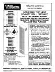
GRAVITY DIRECT VENT
FURNACE
MODEL NOS:
1403612;
1403622
2203612;
2203622
3003612;
3003622
FOR USE WITH
NATURAL GAS ONLY
f-
0tSlG,
_/
APPROVED
®
M()DEL NOS.
1403611;
1403621
2203611 ; 2203621
3003611 ; 3003621
FOR USE WITH
LIQUEFIED
PETROLEUM
(L.P.)
GAS ONLY
--
MODEL
NUMBER
READ THIS OWNERS
MANUAL CAREFULLY
BEFORE YOU INSTALL
YOUR NEW WILLIAMS
WALL FURNACE
INFORMATION
--
NOTE: CANADIAN MODEL NUMBERS THIRD
DIGIT FROM LEFT TO BE:
1 FOR BASIC ALTITUDE
2 FOR HIGH ALTITUDE
EXAMPLE:
MODEL: 1403612 BECOMES 1413612
(0-2000 FT. BASIC ALTITUDE)
OR BECOMES 1423612
(2000-4000- FT. HIGH ALTITUDE)
WARNING: Improper installation,
adjustment, alteration, service or maintenance
can cause injury or property damage.
Refer to this manual. For assistance or
additional information consult a qualified
installer,
service
agency
or the gas
supplier.
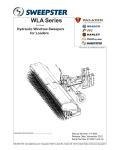
WARNING: Do not install any of these furnaces (Natural
or L.R Gas) in mobile
homes, trailers, or recreational vehicles.
WILLIAMS
PRINTED IN USA
Furnace
5/97
•
•
•
•
Unpacking
Installation
Operation
Repair Parts
WARNING:
If the information
in this
manual is not followed exactly, a fire or explosion may result causing
property
damage, personal injury or loss of life.
Do not store or use gasoline or other flammable vapors and liquids in the vicinity
of this or any other appliance.
WHAT TO DO IF YOU SMELL GAS
• Open all windows.
• Do not try to light any appliance.
• Do not touch any electrical switch; do
not use any phone in your building.
• Extinguish any open flame.
• Immediately call your gas supplier from
a neighbor's
phone. Follow the gas
supplier's
instruction.
• If you cannot reach your gas supplier,
call the fire department.
Installation
and service must be performed by a qualified installer, service
agency or the gas supplier.
Co., 225 Acacia St., Colton, CA 92324
P322256
Contents
Your Warranty ................................
Introduction ..................................
Basic Description ..............................
Optional Accessories ...........................
Safety Rules .................................
Unpack Your Furnace ..........................
Basic Tools Needed ............................
Basic Materials ...............................
Installing Your Wall Furnace .....................
Helpful Installation Information ...................
Locating Wall Furnace and Thermostat ..........
Installation ..................................
Optional Blower Installation .....................
2
3
3
3
4
5
5
5
5
5
6-7
7-9
9
Gas Supply and Piping ......................
Thermostat
Installation ......................
Thermostat Connection At Gas Valve .............
Furnace Technical Information ..................
Cabinet Installation ...........................
Start Up Procedure ...........................
Operating Your Furnace .....................
How To Care For Your Furnace .................
TROUBLESHOOTING
CHART ................
Repair Parts ..............................
SERVICE HINTS ......................
Back
How To Order Repair Parts .............
Back
10-11
11-12
12
13
13
14
15-19
20
21-22
23-29
Cover
Cover
Your Warranty
The Manufacturer,
LIMITED
Williams Furnace Co., warrants this wall furnace
ONE-YEAR
or heater to the original purchaser under the following conditions:
WARRANTY
1. Any part thereof which proves to be defective in material or workmanship within one year from date of original purchase for use will be repaired or replaced at the
Manufacturer's option, Foe its factory.
2. No liability is assumed
LIMITED
EXTENDED
by the Manufacturer for removal or installation labor costs, nor for freight or delivery charges.
WARRANTY
1. in addition to the above limited one-year warranty on the complete unit, any heat exchanger which burns out or rusts under normal installation, use and service
conditions during a period of nine years following expiration of the one-year warranty period will be exchanged for a like or functionally similar part, FOB Manufacturer's factory.
2. No liability
is assumed by the Manufacturer
for removal or installation
labor costs, nor for freight or delivery charges.
LIMITATIONS
1. THIS LIMITED WARRANTY IS THE ONLY WARRANTY MADE eY THE MANUFACTURER. IMPLIED WARRANTIES OF MERCHANTABILITY
OR FITNESS FOR
ANY PARTICULAR PURPOSE ARE LIMITED TO THE SAME ONE YEAR TERM AS THIS EXPRESS WARRANTY. UNDER NO CIRCUMSTANCES
SHALL THE
MANUFACTURER BE LIABLE FOR INCIDENTAL, CONSEQUENTIAL,
SPECIAL OR CONTINGENT DAMAGES OR EXPENSES ARISING DIRECTLY OR INOIRECTLY FROM ANY DEFECT IN THE PRODUCT OR ANY COMPONENT
OR FROM THE USE THEREOE THE REMEDIES SET FORTH HEREIN ARE THE EXCLUSIVE
REMEDIES AVAILABLE TO THE USER AND ARE IN LiEU OF ALL OTHER REMEDIES.
Some states do not allow limitations on how tong an implied warranty lasts, and some states do not allow the exclusion
or consequential damages, so the above limitations or exclusions may not apply to you.
or limitation
of incidental
2. This warranty does not include any charge for labor or installation.
3. This warranty does not extend to painted surfaces nor to damage
or defects resulting from _ccident,
alteration, misuse or abuse, or improper installation.
4. This warranty does not cover claims which do not involve defective workmanship or materials.
DUTIES
OF THE CONSUMER
1. The heating equipment must be installed by a qualified installer and operated in accordance with the installation and homeowner's instructions furnished
equipment.
with the
2. Any travel, diagnostic costs, service labor, and laber to repair the defective unit will be the responsibility of the owner.
3. A bill of sale, cancelled check, payment record or permit should be kept to verify purchase date to establish the warranty period.
4. Have the installer enter the requested information
in the space below.
GENERAL
1, The Manufacturer
neither assumes nor authorizes any person to assume for it any other obligation or liability in connection
with said equipment.
2. Service under this warranty should be obtained by contacting your dealer. Provide the dealer with the model number, serial number and purchase date verification.
3. If, within a reasonable time after contacting your dealer, satisfactory service has not been received, contact: Customer Service Department, 225 Acacia St., Coiton,
CA 92324, for assistance.
4. THIS WARRANTY
INSTALLATION
Model
Orig,
GIVES YOU SPECIFIC
LEGAL RIGHTS, AND YOU MAY ALSO HAVE OTHER
RIGHTS WHICH VARY FROM STATE TO STATE.
INFORMATION
No.
Serial
No
Purchaser_
Address
City and State
Zip
Dealer
Address.
City and State
Zip
Installation date
Signed by.
.(Dealer or
authorized representative who certifies that this appliance has been installed in accordance with Manufacturer's instructions and
local codes.)
--2--
Introduction
Please read our instructions before you install and use your furnace. This will help you obtain the full value from this
furnace. It could help you avoid needless service costs, if the answer to the problem is found within this instruction
manual.
Basic Description
The sealed combustion system draws combustion air
directly from outdoors into the combustion chamber and
combustion gases are discharged directly to the outdoors
through tubes mounted to the rear of the furnace.
Your direct vent wall furnace is shipped ready to install
against an exterior wall up to 9 inches thick. For walls
greater than 9 inches, and up to 24 inches thick, use an
optional VENT EXTENSION KIT listed under OPTIONAL
ACCESSORIES.
The furnace heat exchanger is built of heavy gauge steel
treated for corrosion resistance.
The furnace may burn either Natural or L.R Gas, depending on the model you have purchased.
The furnace cabinet is also constructed of heavy gauge
steel and has an enamel paint finish.
The furnace controls are located behind an access door
on the lower front of the furnace. All models are equipped
with American Gas Association and Canadian Gas
Association listed gas valves and pilots.
No electric power is required unless furnace is equipped
with an optional blower accessory.
Always consult your local heating or plumbing inspector,
building department or gas utility company regarding
regulations, codes or ordinances which apply to the installation of a direct vent furnace.
Optional
MODELS:
MODELS 1403611, 1403612, 2203611, 2203612, 3003611
and 3003612 are equipped with a built-in thermostat.
MODELS 1403621, 1403622, 2203621, 2203622, 3003621
and 3003622 are equipped with a wall thermostat.
Accessories
1403611; 1403612; 1403621; 1403622
ALL MODELS:
For walls greater than 9 inches thick and up to 24 inches
thick, use one of the following Vent Extension Kits:
KIT NUMBER
9304
9303
MODELS:
Various Face Panel colors may be used on all models. All
are constructed of heavy gauge steel with your choice of
colored enamel paint finish.
WALL THICKNESS
9 inches to 15 inches
15 inches to 24 inches
MODELS:
4309
4310
4311
4312
2203611; 2203612; 2203621; 2203622
3003611 ; 3003612; 3003621 ; 3003622
For walls greater than 9 inches thick and up to 24 inches
thick, use one of the following Vent Extension Kits:
KIT NUMBER
9301
9302
9303
MODELS:
Decorator Face Panel Colors
MODELS:
WALL THICKNESS
9 inches to 15 inches
15 inches to 24 inches
(220 model series only)
15 inches to 24 inches
(140 (or) 300 model series)
4313
4314
4315
4316
1403611 ; 1403612; 1403621; 1403622
(Almond)
(Black)
(Red)
(White)
2203611; 2203612; 2203621; 2203622
3003611; 3003612; 3003621; 3003622
(Almond)
(Black)
(Red)
(White)
ALL MODELS:
2203611; 2203612; 2203621; 2203622
3003611; 3003612; 3003621; 3003622
For additional vent cap protection, Vent Cap Guard 9308
may be used. This mounts to the outside of the exterior
wall over the vent cap.
To increase circulation of warmed air within the heated
space, you may use Blower Accessory Kit 2302, which is
equipped with a two-speed fan and automatic fan switch.
NOTE
ALL MODELS
For walls less than 41/2 inches thick, a thin Wall Collar Kit
9307 may be used to increase wall thickness if wood strips
are undesirable.
--3--
Accessories are identified on the carton by their manufacturing number. (For example: 9301; 9302; 9303.) These
manufacturing numbers are also listed on the furnace
rating plate so you can be sure you have the accessory
that fits your furnace.
Safety Rules
WARNING
umn. The maximum inlet gas supply pressure is 13"
water column.
READ THESE RULES AND THE INSTRUCTIONS
CAREFULLY.
FAILURE TO FOLLOW THESE
RULES AND INSTRUCTIONS COULD CAUSE A
MALFUNCTION OFTHE FURNACE. THIS COULD
RESULT tN DEATH, SERIOUS BODILY INJURY,
AND/OR PROPERTY DAMAGE.
ANY SAFETY SCREEN, GUARD OR PARTS REMOVED FOR SERVICING AN APPLIANCE MUST BE
REPLACED PRIOR TO OPERATING THE APPLIANCE TO AVOID PROPERTY DAMAGE, BODILY
INJURY OR DEATH.
,
INSTALLATION MUST CONFORM TO LOCAL CODES. IN
THE ABSENCE OF LOCAL CODES, INSTALLATION MUST
CONFORM WITH THE NATIONAL FUEL GAS CODE, ANSI
Z223.1. THE APPLIANCE, WHEN INSTALLED, MUST BE
ELECTRICALLY CONNECTED AND GROUNDED
IN
ACCORDANCE
WITH LOCAL CODES OR, IN THE
ABSENCE OF LOCAL CODES, WITH THE CURRENT
NATIONAL ELECTRICAL CODE ANSI/NFPA NO. 70.
9.
1. INSTALLATION MUST CONFORM TO LOCAL
CODES OR, IN THE ABSENCE OF LOCAL
CODES, THE CURRENT CAN/CGA B149 INSTALLATION CODE.
2. THE APPLIANCE, WHEN INSTALLED, MUST BE
ELECTRICALLY CONNECTED AND GROUNDED IN ACCORDANCE WITH LOCAL CODES OR,
IN THE ABSENCE OF LOCAL CODES, WITH
THE CURRENT CSA C22.1 CANADIAN ELECTRICAL CODE.
3. FIELD CONVERSIONS FOR HIGH ALTITUDE
ARE NOT PERMITTED IN CANADA.
4. REFERENCE
IS MADE IN THIS MANUAL
REGARDING GAS TYPE AS L.RG. BE ADVISED
THAT L.RG. IS NOT AVAILABLE IN CANADA,
REFER TO PROPANE/L.R GAS.
11. NEVER test for gas leaks with an open flame. Use
soap suds to check all gas connections. This will avoid
the possibility of fire or explosion.
12. ALLOW furnace to cool before servicing. Always shut
off electricity and gas to furnace when working on it.
This will prevent any electrical shocks or burns.
13. DUE TO HIGH TEMPERATURES, locate the furnace
out of traffic and away from furniture and draperies.
14. ALERT children and adults to the hazards of high surface temperature and to keep away to avoid burns or
clothing ignition.
15. CAREFULLY supervise young children when they are
in the same room with the furnace.
16. DO NOT place clothing or other flammable
on or near furnace.
USE ONLY MANUFACTURER'S
REPLACEMENT
PARTS. USE OF ANY OTHER PARTS COULD CAUSE
INJURY OR DEATH.
2.
DO NOT install this furnace in an alcove.
3.
DO NOT install these furnaces in a travel trailer,
recreational vehicle or mobile home.
4.
MAINTAIN all clearances
specified in section
"Locating Wall Furnace and Thermostat" and "Vent
Installation."
5.
18. BEFORE INSTALLING: To avoid electrical shock, turn
off electrical circuits that pass through the wall where
you are going to install the furnace.
19. BE AWARE of good safety practices by wearing personal protective equipment such as gloves and safety glasses to avoid being injured by sharp metal edges
in or around furnace and while cutting or drilling holes
in wood and or sheet metal,
For Natural gas, the minimum inlet gas supply
pressure for the purpose of input adjustment is 5" column. The maximum inlet gas supply pressure is 7"
water column.
For L.R gas, the minimum inlet gas supply pressure
for the purpose of input adjustment is 11" water col-
I
material
17. INSTALLATION and REPAIR must be done by a qualified service person. The appliance should be inspected
before use and at least annually by a professional service person. More frequent cleaning may be required
due to excessive lint from carpeting, bedding material,
etc. It is imperative that control ,compartments, burners
and circulating air passages be kept clean.
BE SURE furnace is for type of gas to be used. Check
the rating plate by the gas valve in the lower cabinet.
Do not change it to use other gases. Unsafe operation could result and could cause bodily injury and
death.
6,
BE SURE to provide for adequate combustion and
ventilation air. See page 7. The flow of this air to the
furnace must not be blocked.
10. NEVER vent flue gases into another room, a fireplace
or any space inside a building. This could cause properry damage, bodily injury or death.
IN CANADA
1,
INSTALL the furnace vent directly to the outdoors, so
that harmful gasses will not collect inside the building.
Follow the venting instructions for your type installation exactly. Use only the type and size of vent pipe
and fittings specified.
20. CAUTION: Label all wires prior to disconnection when
servicing controls. Wiring errors can cause improper
and dangerous operation. Verify proper operation after
servicing.
WARNING
DO NOT USE THIS HEATER IF ANY PART HAS BEEN UNDER WATER. IMMEDIATELY CALL A QUALIFIED
SERVICE TECHNICIAN TO INSPECT THE HEATER AND TO REPLACE ANY PART OF THE CONTROL SYSTEM
AND ANY GAS CONTROL WHICH HAS BEEN UNDER WATER.
4,.,,-4
m
Unpack
Your Furnace
lost or damaged before you need them.
This direct-vent furnace is packaged complete including
the vent cap, vent tube and air inlet tube ready for installation on an exterior wall with a total thickness of from
5 inches minimum to a maximum of 9 inches.
NOTE
Check the burner rating plate, located in burner compartment, to make sure your furnace is equipped to operate
on the type of gas available (either Natural or L IR Gas).
Do NOT convert unit from Natural Gas to L.R Gas or from
L.R Gas to Natural.
Open the carton and remove all parts.
Examine all packing material carefully. Look for loose parts
before discarding. Store all parts where they cannot be
Basic
Tools
Needed
Tin snips
8" adjustable wrench
12" adjustable wrench
Key hole saw or Sabre saw
Hack saw
2 - 10" or 12" pipe wrenches
Gloves and safety glasses
Hand drill or properly grounded electric drill
Expansion bit 1/2" to 1-5/8" or 1/2" or 1-1/2" blade bits
1/8" and 3/16" drill bit (metal)
6 ft. folding rule or tape measure
Screwdriver (Phillips head)
Pliers (wire cutting)
Hammer
Stud Iocator or small finish nails
Basic Materials
Pipe and fittings to make connections
page 10).
Pipe joint compound resistant to L.IR Gases.
to furnace (see
Electrical wiring supplies as needed for optional blower
if equipped (see page 9).
Caulking compound - silicone rubber with a temperature
rating of 500°E
Minimum wire size is #14 gauge copper.
Do not use types advertised as paintable or for bath tub
use as most contain fillers and will not withstand high
temperatures.
Installing
Your Wall Furnace
IMPORTANT
The following steps are needed for proper installation and
safe operation of your furnace. If you have any doubts as
to any requirements, check with local authorities for local
and state codes affecting the installation.
For satisfactory and trouble-free operation be sure to:
1. Properly locate the furnace within the space to be
heated.
Obtain professional help where needed.
DO NOT install these furnaces in a travel trailer, recreational vehicle, or moble home.
2. Provide for adequate combustion air around vent cap
on outside, see Fig. 1, page 6 and adequate air circulation around cabinet inside the open room, see Fig. 2,
page 6.
3. Maintain all minimum clearances on pages 6 and 7
which apply to your furnace model.
Helpful
Installation
Information
The following booklets will help you in making the installation. Check at the library or they may be purchased from
the source listed below.
American National Standard Z223.1 current edition "National Fuel Gas Code."
In Canada: CAN/CGA-B149.1 (.2) Canadian Standard.
ANSI/NFPA 70 current edition "National Electrical Code."
In Canada: C22.1 Canadian Electrical Code.
Obtain from - American National Standards Institute, Inc.,
1430 Broadway, New York, NY 10018.
--5--
Locating
Wall Furnace
Consider the following points before attempting to install
the furnace:
MINIMUM
DIMENSIONS
FROM VENT
ALL MODELS
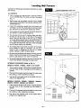
1. This is a direct vent wall furnace. It must be installed
on an OUTSIDE WALL for proper venting of flue gases
(Fig. 1).
2. Wall furnace can be surface mounted on an outside
wall up to 24 inches thick when using an optional VENT
EXTENSION KIT.
3o.,,
,
3. Check the clearances needed from the furnace and
vent (Figs. 1 and 2). You must place the furnace where
you will have no less than the clearances shown.
4. The outside vent must be at least 18 inches away from
any window or other building opening.
5. The furnace will not work if anything stops free entry
of fresh air into the vent, or free flow of flue gases
from it. Be sure the center of the vent cap is at least
12 inches above ground level or shrubs as shown in
Fig. 1. Make sure shrubs are kept trimmed. It must also
be at least 18 inches from any wall or other blockage
and 30 inches below any overhang.
6. Try to place the furnace near the center of the space
to be heated for good air circulation. Do not put it
behind a door or draperies. Do not put in a closet,
alcove, hallway or other confined space.
7. Be sure that gas piping and electrical wiring (optional
blower only) can be brought to the furnace. See sections on gas piping for your type of mounting.
INTERIOR
CLEARANCES
8. To provide adequate clearance and service access, the
front of the furnace must face the open room.
INTERIOR CLEARANCES
(Refer to Fig. 2)
(1) 18" MIN.
(2) 24" MIN.
MODELS 1403612, 1403622, 1403611 and 1403621
1. There must be at least 1-3/16 inches of space between
the floor (top of floor covering) and the bottom of
cabinet.
2. The top of the furnace must be at least 18 inches from
the ceiling or other projecting overhang.
3. The side of the furnace must not be closer than 2 inches to an adjacent wall.
MODELS 2203612, 2203611, 2203622,
3003612, 3003611, 3003622 and 3003621
2203621,
1. There must be at least 5-1/2 inches of space between
the floor (top of floor covering) and the bottom of
cabinet.
MOOEL: 1403611
1403612
1403621
1403622
2. The top of the furnace must be at least 24 inches from
the ceiling or other projecting overhang.
3. The side of the furnace must not be closer than 2
inches to an adjacent wall.
(2)
MODEL: 2203611;
2203621;
3003611;
3003621;
2203612
2203622
3003612
3003622
RG,
--6--
Locating
MODELS
1403622, 1403621, 2203622,
3003622 and 3003621
Wall Furnace
(cont.)
HOT SPOTS:
COLD SPOTS:
Concealed pipes or ducts Concealed pipes or ducts
Stairwells - drafts
Fireplaces
Doors - drafts
Registers
TV sets
Unheated rooms on
Radios
other side of wall
DEAD SPOTS:
Lamps
Behind doors
Direct sunlight
Kitchen
Corners and alcoves
After picking a location that meets the requirements, inspect the wall, floor and outside areas. Make sure there
are no pipes, wiring, or anything else that would interfere
with furnace or vent or thermostat installation. If required,
move them or pick a new location.
2203621,
(All other models have a built-in thermostat)
Choose a location for the thermostat about 5 feet above
the floor on an inside wall. The thermostat wire supplied
with your furnace is 20 feet long, which should be enough
to run up through the attic so the thermostat can be a maximum of 16 feet from furnace measured in a straight line,
or approximately 12 feet from the furnace if the wire is run
under the floor. The thermostat should be sensing average
room temperature, avoid the following:
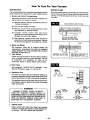
Installation
BEFORE YOU BEGIN: To avoid electrical shock turn off
electrical circuits that pass through the wall where you are
going to install the furnace.
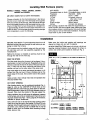
Make sure the inside and outside wall openings
aligned so tubes and vent will fit properly.
are
IN NEW CONSTRUCTION frame in 9-1/4 inch x 9-1/4 inch
opening centered between studs spaced 16 inches on
center, and center point located as noted per Fig. 3.
This furnace must be installed using only the vent tube,
air inlet tube and vent cap assembly supplied by the
manufacturer.
Before the furnace is installed an opening must be cut
through the wall for the vent cap.
i
NOllE: S-I./,, x 9-1/40I:'£NblG MAYBE ROUNDOR SQUARECUT.
FIND THE STUDS
Find the studs where the furnace is to be placed. Use a
stud Iocator or small finishing nails. Repeatedly drive and
remove a nail into the wall in the area of the stud until you
find it. Then find one side. Leave the nail there. Drive
another nail just on the other side of the same stud.
The inside edge of the other stud should be about 14-1/2
inches from the one found. Drive a finishing nail on the
inside edge of this stud, then another nail on the outside
edge.
Using a level, draw vertical lines that will represent the
two stud center lines.
CUT VENT OPENING
After locating studs, use the cardboard template (Fig. 4,
page 8). Line up the CENTER OF STUD lines on the
template with the center lines you have drawn on the wall.
Use the template to draw the 9-1/4 inch diameter circle on
the wall. Then mark the location of the gas supply line.
Using a window, door or wall corner for reference, measure
to find where vent will be on outside wall. Check to be sure
of proper clearances (Figs. 1 and 2, page 6). If necessary,
relocate for proper clearances.
Drill a 1/4 inch hole in the wall at the vent opening center
mark all the way through to the outside. Cut the 9-1/4 inch
diameter hole through inside wall. Using the 1/4 inch hole
as center, cut a matching hole in outside wall. It may be
petter to work from the outside when breaking through
brick, stone or tile.
(I)
MOD_
1403611; 1403612
144)3621; 1403622
(2) MOOELS: 2203611;
2203621;
2203612;
2203622;
3003611; 3003612
3003621; 3003622
RL3
--7--
Installation
GAS AND ELECTRICAL
SUPPLY OPENINGS
(cont.)
IMPORTANT
Holes must be drilled for the gas line (and electrical
supply if you use an optional Blower Kit). Drill a 1-1/2
inch hole in wall for gas line where indicated on
cardboard template or refer to Fig. 3, page 7. You will
have to determine whether the gas line will enter the
home through the outside wall or wall floor plate. These
instructions can only guide you in where the gas line
will enter the furnace.
TEMPLATE
For walls more than 9 inches thick, read note below.
NOTE
(Refer to Fig.5.) The vent tube "C" and air inlet tube "D"
are factory installed for walls up to 9 inches thick only. For
walt thicknesses up to 24 inches, follow the instructions
packed with the appropriate factory built VENT EXTENSION KIT. See OPTIONAL ACCESSORIES on page 3.
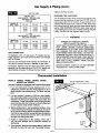
FURNACE MOUNTING
Set the furnace body against the wall, legs on the floor,
with the vent tubes ("C" and "D" Fig. 5) extending
through the spacer plate.
TEMPLATE
Fasten the furnace to the wall through holes at the top and
bottom of the support legs using four (4) #8 roundhead
(long) screws ("F" Fig. 5) provided.
Push the air inlet shield "J" on from the exterior side of
wall. Rotate the air inlet shield until notches on the end
of the tube are straddling the standoff tabs on the mounting spacer plate "A". Trim the air inlet shield "J" flush with
the exterior of the wall.
The gas
or done
ed. See
PIPING,
line can be run at this time
after the furnace is mountsection GAS SUPPLY and
page 10.
FASIEN
LE
TO WALL
©
INLET SHIELD
TRIM FLUSH Wl_r_
EX"[ZRIOR WALL
Q
No electric power is required unless
furnace is equipped with an optional
blower kit.
F
EMBOSSED
"TOP w
Do not connect 115V service line to
the gas valve or wall thermostat.
MODELS WITH OPTIONAL
BLOWER KIT 2302 ONLY
Install an electrical junction box at the
location shown in Fig. 7, page 9.
Route the 115V electrical supply wiring to the junction box making sure
to leave enough excess wire to make
connections later.
MAS_C(_
PLATE TO
INSTALL SPACER PLATE
Install the mounting spacer plate ("A"
Fig. 5) with spacers entering and
centered within the 9-114 inch vent
opening in wall. Level top of spacer
plate (embossed top) and fasten to interior wall using six (6) #8 roundhead
(long) screws ("B" Fig. 5) provided.
WALL (_
FASTEN
TO WALL
®
RG.
_8I
5
Installation
(cont.)
INSTALL VENT CAP
POSITION
Outside, place a single strip of mastic (provided) around
the back flange of the vent cap ("G" Fig. 5, page 8). Install the vent cap by inserting it into the air inlet tube and
over the vent tube.
OF VENT CAP
EXTERIOR
WALL
IMPORTANT
The top of the vent cap is embossed "TOP". Install it in
the correct position to prevent water from entering the wall.
Level the vent cap and attach it to the outside wall with
four (4) #8 roundhead (long) screws (Fig. 6).
If the wall surface is not flat (shiplapped siding, etc.) or
less than 5 inches thickness use Thin Wall Collar Kit (9307)
or, build up a flat surface with wood strips. Do not tilt or
bend cap to fit uneven surfaces. The vent cap flange must
be tight against the wall to prevent rain or wind penetration. Use standard caulking compound if required (not
provided).
For brick, masonry or plaster walls, it may be necessary
to use lag screws or expanding anchor bolts which are
not furnished with the furnace.
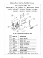
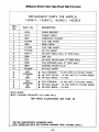
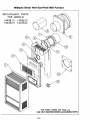
Optional
Blower
Installation
1. Remove knock-out plates "A" and "B" from right side
of furnace inner casing.
2. Remove junction box cover, place blower and junction
box assembly in position shown and fasten to inner casing through pre-punched holes with screws "C" and
"D" provided.
\
\
k
and Operating
Instructions
The automatic fan switch "E" turns on the blower after
the heater has been operating a few minutes and turns
off the blower after the heater is shut off.
NOTE
4. Replace junction box cover.
Blower will not operate unless fan switch is pulled to "On"
position, either "High" or "Low." To check "On" position,
turn automatic fan switch "E" to 70, then pull chain on
switch to obtain High, Low or Off position. Set the fan
switch dial at 110 and readjust higher or lower as
necessary to obtain blower operation within 4 to 5 minutes
after the main burner is in operation.
5. After blower and junction box are installed, rotate
bushing "H" if needed to prevent motor wire binding
against blower case.
The unit must be electrically grounded in accordance with
ANSI/NFPA 70 current edition of the "National Electrical
Code." In Canada: FollowC22.1 Canadian Electrical Code.
3. Remove knock-out "G" from bottom of junction box
and install 115V line in accordance with local electrical
code, connecting as shown on the wiring diagram
below.
IMPORTANT: 011 yearly with SAE 20 high tamp o11.
BLOWER ACCESSORY
r_lR Swt,¢h
i
KIT 2302
Illl4
• lille•
.
I z- _;/4- i
I
=,-t/r
I
i
16-1/2"
i "J'BOX
L1
115V
I
I
_.=
•
NEUT
=w,t¢_
-'--8
0
SCREW
RIGHT
,,........... ,......... I_ :::'.'J,_:'
.... ,. ............ = I B _-"_:._,,_-,.,
NOT(:
F1NIItlfl)
i
Fact_
,,,..-........
,-,.I ;
t, _.
4/,4
i,le.=4i f le4t. to_
•ekl er Nle o qllvll _t4.
¢.
U
w_N
i_ .*lltqt
_r 1ill
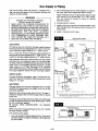
Gas Supply
Gas control valve, within the furnace, is shipped with a
seal over gas inlet tapping. Do not remove this seal until
ready to connect piping.
& Piping
2,
Apply moderate amount of good quality dope to pipe
only, leaving 2 end threads bare. If L.R Gas installation, use compound resistant to action of liquefied
petroleum gases.
WARNING
DANGER OF PROPERTY DAMAGE,
BODILY INJURY OR DEATH.
MAKE SURE THE FURNACE IS EQUIPPED TO
OPERATE ON THE TYPE OF GAS AVAILABLE.
MODELS DESIGNATED AS NATURAL GAS ARE TO
BE USED WITH NATURAL GAS ONLY. FURNACE
DESIGNATED
FOR USE WITH LIQUEFIED
PETROLEUM (L.R) GAS HAVE ORIFICES SIZED
FOR COMMERCIALLY
PURE PROPANE GAS.
THEY CANNOT BE USED WITH BUTANE OR A
MIXTURE OF BUTANE AND PROPANE.
Do not thread pipe too far. Valve distortion or malfunction may result from excess pipe within control.
Use ground joint unions.
4. Install a drip leg to trap dirt and moisture before it can
enter the gas valve. Drip leg must be a minimum of 3
inches long.
3,
5. Install a manual shut-off valve.
GAS SUPPLY PIPING
DROP
GAS SUPP_
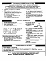
For Natural Gas, the minimum inlet gas supply pressure
for the purpose of input adjustment is 5" column. The maximum inlet gas supply pressure is 7" water column.
]
I
I
I
PIPED
J_
._;:_Hor
;R0UN0
GAS
JOINT
UNION
SUPPLY
,ZON r AL i 'l
ql,
For L.R Gas, the minimum inlet gas supply pressure for
the purpose of input adjustment is 11" water column. The
maximum inlet gas supply pressure is 13" water column.
RISER
l,_
Gas pressures and input to the burners must not exceed
the rated input and pressure shown on the rating plate.
On Natural Gas the manifold pressure should be 4 inches
water column. The manifold pressure should be 11 inches
water column for L.R Gas. See page 13 for operation
above 2000 feet altitude. Orifice change may be required
to suit gas supplied. Check with your local gas supplier.
176 2 mini
GAS
MiNiMUMor_oP__"
SY_ANuAtSHUT
UA_AS_
OFF
SUPPLY
_
3 ,_
ORIFICE SIZES
! (
Furnace Technical Information, page 13, shows the correct orifice sizes for the different input ratings when using
Natural or L.R Gas.
I
SUPPLY
1/6 _ r.nd
\ l'X--
!
GAUGE
I I
hi',se!,,
GAS PIPING
'
I
I I
The gas supply line must be of adequate size to handle
the BTU/HR requirements and length of the run for the
unit being installed.
Determine the minimum pipe size from Fig. 10, page 11,
basing the length of the run from the gas meter or source
to the unit.
_/_
_"
ALL
BEttO5
_.AklTION
ro
AGE
iN
M[TAL
511UT
PN[VENT
WIt[N
I.IC
OyF
GAS
IIN_TAI
_ LJHING
[14[
FIt(IM
M_IN
FILLING
LAIlON
IS
514OULO
_AS
SUppI.y
Ttl[
WORK
B[
5_,4OOTH
gEl'Oil[
#.R_.A
N[MOVING
TE.ST
Eft[)
_Ofl
GAS
COMPI_ET[
All piping must comply with local codes and ordinances
or with the National Fuel Gas Code (ANSI Z223.1 NFPA
No. 54), whichever applies.
IN Canada: Follow CAN/CGA-B149.1 (.2) Canadian
Standard.
PROPER
Refer to Fig. 8 for the general layout at the unit. It shows
the basic fittings needed.
The following rules apply:
1. Use new, properly reamed pipe free from chips such
as steel or black iron pipe and fittings or other approved
by local codes.
--10n
2 IMPERFECT
THREADS
PIPING
CONTRO
L
PRACTICE
USE
MOOERATE
AMOUNT
OF
DOP[
L[AK
12,_p
Gas Supply
& Piping (cont.)
Tighten all joints securely.
GAS PtPE SIZES
CHECKING THE GAS PIPING
NATURAL GAS
PIPE CAPACITY - BTU PER HOUR
(INCLUDES FITTINGS)
PIPE SIZE
LENGTH OF
PIPE - FEET
1/2 inch
3/4 inch
1 inch
20
40
60
92,000
63,000
50,000
190,000
130,000
105,000
350,000
245,000
195,000
Test all piping for leaks. When checking gas piping to the
furnace with gas pressure at less than 1/2 PSI, shut off
manual gas valve for the furnace. If gas piping is to be
checked with the pressure at or above 1/2 PSI, the furnace
and manual shut off valve must be disconnected during
testing. (SEE WARNING BELOW.) Apply soap suds (or
a liquid detergent) to each joint. Bubbles forming indicates
a leak. Correct even the slightest leak at once.
L.P. GAS
PIPE CAPACITY - BTU PER HOUR
(INCLUDES
WARNING
FITTINGS)
LENGTH OF
PIPE - FEET
112 inch
3/4 inch
1 inch
20
40
60
189,000
129,000
103,000
393,000
267,000
217,000
732,000
504,000
409,000
DANGER OF PROPERTY DAMAGE,
BODILY INJURY OR DEATH.
NEVER USE A MATCH OR OPEN FLAME TO TEST
FOR LEAKS. NEVER
EXCEED SPECIFIED
PRESSURES FOR TESTING. HIGH PRESSURES
MAY DAMAGE THE GAS VALVE AND CAUSE
OVER-FIRING WHICH MAY RESULT IN HEAT EXCHANGER FAILURE. LIQUID PETROLEUM (L.P.)
GAS IS HEAVIER THAN AIR AND IT WILL SE'I-FLE
IN ANY LOW AREA, INCLUDING OPEN DEPRESSION AND IT WILL REMAIN THERE UNLESS
AREA IS VENTILATED.
GAS CONNECTION
If installation is for L.P. Gas have L.P. installer use twostage regulation and make all connections from storage
tank to furnace.
Use two pipe wrenches when making the connection to
the valve to prevent turning or damage to gas valve.
Connection between shut off valve and burner control
assembly can be made with an A.G.A./C.G.A. design certified flexible connector if allowed by local codes.
Thermostat
MODELS
1403622, 1403621, 2203622,
3003622 and 3003621
NEVER ATTEMPT START-UP OF UNIT BEFORE
THOROUGHLY VENTILATING AREA.
Installation
2203621,
ROUTE THERMOSTAT
(All other models are equipped with a built-in thermostat)
1. If an old thermostat is being replaced and is in'a
satisfactory location and the wiring appears to be in
good condition, use existing wiring. If in doubt, use new
wire.
2. If a new location is chosen or if this is a new installation, thermostat cable must first be run to the location
selected. All wiring must agree with local codes and
ordinances. These instructions cover bringing the wire
down from the attic but it can be run from a basement
or crawl space using similar methods.
3. Before drilling hole in wall at selected location, drive
a small finishing nail through the ceiling in the corner
of the wall and ceiling above the thermostat location.
Pull the nail out and push a small stiff wire through the
hole so it can be found in the attic. Drill a 1/2 inch hole
through the ceiling wall plate.
4. Probe for obstructions in the partition. Then drill a
112 inch hole through wall at selected location for
thermostat.
SMAL I.
FINISH
NAi l, 10
LOCATE
H_ADER
CABL[
STIF
10
WtRE
SNAG
CABLE
5. From the attic, feed the thermostat cable or a stiff wire
through the wall until even with thermostat location.
--11 m
CABLE
Thermostat
Installation
6. Snag thermostat cable through wall so that 6 inches
of cable protrudes.
7. Route cable to wall furnace leaving enough excess
cable to make the connections at the gas valve.
MOUNTING
THE THERMOSTAT
1. To remove the thermostat cover, grasp cover and pull
straight outward. Carefully remove and discard the
packing tab protecting the switch contacts.
2. Connect thermostat wires to the terminal screws on the
back of thermostat base.
Thermostat
MODELS
1403622, 1403621, 2203622,
3003622 and 3003621
3. Push any excess wire back through hole in wall and
plug hole with insulation to prevent drafts from affecting thermostat operation.
4. Being sure to level thermostat for best appearance,
fasten thermostat base to wall through mounting holes
with screws provided.
5. Replace the thermostat
cover.
NOTE
Refer to installation instructions packed in the thermostat
carton if you have any doubt about the above procedures.
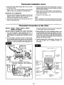
Connection
2203621,
at Gas Valve
down from the attic but it can be run from a basement
or crawl space using similar methods.
(All other models are equipped with a built-in thermostat)
3.
1. If an old thermostat is being replaced and is in a
satisfactory location and the wiring appears to be in
good condition, use existing wiring. If in doubt, use new
wire.
2. If a new location is chosen or if this is a new installation, thermostat cable must first be run to the location
selected. All wiring must agree with local codes and
ordinances. These instructions cover bringing the wire
THERMOSTAT
(cont.)
4.
Before drilling hole in wall at selected location, drive
a small finishing nail through the ceiling in the corner
of the wall and ceiling above the thermostat location.
Pull the nail out and push a small stiff wire through the
hole so it can be found in the attic. Drill a 1/2 inch hole
through the ceiling wall plate.
Probe for obstructions in the partition. Then drill a 1/2
inch hole through wall at selected location for
thermostat.
GENERATOR
INNER
£D WIRE
CASING
WHI'I_ WIRE
1
V LUAMS
P121200
(OR)
(r
SHIELD
_)¢mm.o _
P171600
JUMPER
WILUAMS P295200A
GENERATOR
_) _i
PILOT
OBSERVATION
DOOR
(:PEEP-HOLE
COVER)
(OR) P295201A
THERMOSTAT
WIRES
-MANUAL
SPARK
iGNITOR
PRESS
REPEATEDLY
DOOR
GROUND
JOINT UNION
FITTING
DRIP LEG
GREEN
KNOB
--12--
MANUAL
SHUT-OFF
VALVE
CONTROL
VALVE
RG. 13
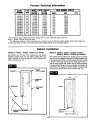
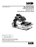
Furnace
MODEl.
NUIBMm
TYPE
GAS
1403612
1403611
1403622
1403621
2203612
2203611
2203622
2203621
3003612
3003611
3003622
3003621
NAT.
L.P.G.
NAT.
LP.G.
NAT.
LP.G.
NAT.
LP.G.
NAT.
LP.G.
NAT.
LP.G.
INPUT *
RATING
IrTU/NR
14,000
14,000
14,000
14,000
22,000
22,000
22,000
22,000
30,000
30,000
30,000
30,000
Technical
HTG. CAPAO.
RATING
IITU/IHfl
10,039
10,039
10,039
10,039
16,462
16,462
16,462
16,462
21,849
21,849
21,849
21,849
Information
MAIN BURNER OfliPJC8
DILL
DEC.
#51
0670
#58
#51
#58
#45
#55
#45
#55
#42
#53
#42
#53
.0420
.0670
.0420
.0820
.0520
.0820
.0520
.0935
.0595
.0935
.0595
QTY.
*For elevations above 2000 feet reduce ratings 4% for each 1000 feet above sea level.
Btuh = British Thermal Units per hour.
The efficiency ratging of these appliances is a product thermal efficiency rating system determined under continuous operating conditions and was determined independently of any installed system.
Cabinet
MODELS
Installation
1403612, 1403622, 1403611 and 1403621
MODELS
Set cabinet over furnace body, dropping rear top flange
between support legs and wall. Open cabinet door and
attach cabinet to inner casing with two (2) sheet metal
(short) screws (Fig. 14).
CABINET _
"_'m-p'p'p'p'p'p'p_
-Hr
REAR
TOP FLANGE
2203612, 2203611, 2203622, 2203621,
3003612, 3003611, 3003622 and 3003621
Set cabinet over furnace body, dropping rear top flange
into slot in top of Spacer Plate and into slots between support legs and wall. When correctly positioned side to side,
a dimple on the rear top flange will slide against the inside of each support leg. Attach two (2) tension springs
through bottom flange of heat exchanger and bottom of
cabinet (Fig. 15). Fasten trim strip to bottom of support legs
using two (2) sheet metal (short) screws (Fig. 15).
CABINET --
i
:
i
i
I
I
BINET
DOOR
(CASING)
T__
--13--:
_
Start-Up
Procedure
Start the furnace using the procedures in section
Operating Your Furnace on pages 15 through 19.
CHECK THE GAS INPUT (NATURAL GAS ONLY)
WARNING
WARNING
NATURAL GAS HEATING VALUE (BTU PER CUBIC
FOOT) CAN VARY SIGNIFICANTLY, THEREFORE,
IT IS THE INSTALLER'S RESPONSIBILITY TO SEE
THAT BTU INPUT TO THE FURNACE IS ADJUSTED
PROPERLY. FAILURE TO DO SO COULD CAUSE
HEAT EXCHANGER FAILURE, ASPHYXIATION, FIRE
OR EXPLOSION, RESULTING IN DAMAGE, BODILY
INJURY OR DEATH. REFER TO THE NATURAL
FUEL GAS CODE (NFPA-54) TO BE SURE THE FURNACE IS BURNING FUEL AT THE PROPER RATE.
DANGER OF BODILY INJURY OR DEATH
LIQUEFIED PETROLEUM (L.E) GAS IS HEAVIER
THAN AIR AND IT WILL SETTLE IN ANY LOW
AREA, INCLUDING OPEN DEPRESSIONS AND IT
WILL REMAIN
THERE
UNLESS
AREA IS
VENTILATED.
NEVER ATTEMPT START-UP OF UNIT BEFORE
THOROUGHLY VENTILATING AREA•
Check the furnace operation as outlined in the following
instructions• If any sparking, odors or unusual noises are
encountered,
shut off electrical power immediately.
Recheck for wiring errors, or obstructions in or near optional blower motor•
NOTICE:
During the initial firing of this unit some smoke and odor
may occur• We recommend ventilating the area during this
initial "break in period."
CHECK GASlNPUT
AND PRESSURES
For furnace located at altitudes between sea level and
2000 feet, the measured input must not be greater than
the input shown on the rating plate of the furnace. For
elevations above 2000 feet, the measured input must not
exceed the input of the rating plate reduced by 4 percent
for each 1000 feet that the furnace is above sea level.
Gas supply pressure and manifold pressure with the
burners operating must also be as specified on the rating
plate.
TYPE OF GAS
Natural
L.R
MANIFOLD
Underfiringcould cause inadequate heat, excessivecondensation or ignition problems. Overfiring could cause sooting flame impingement or overheating of heat exchanger•
Before starting natural gas input check, obtain heating
value of gas (BTU per cubic foot) at standard conditions
from your local supplier. This factor is used in "Check the
Gas Input" section and procedure.
To measure the input using the gas meter, proceed as
follows:
Step 1: Turn off gas supply to all other appliances except
the furnace.
Step 2: With the furnace operating, time the smallest dial
on the meter for one complete revolution. If this
is a 2 cubic foot dial, divide the seconds by 2; if
it is a 1 cubic foot dial, use the time in seconds
as is. (3,600 = Sec. Per Hr.) This gives the
seconds per cubic foot of gas being delivered to
• the furnace.
Step 3: Assuming natural gas with a heating value of 1000
Btu per cubic foot and 34 seconds per cubic foot
as determined by step (2), then:
Input: 1,000 X 3,600 + 34 = 106,000 Btu Per Hour
This measured input must not be greater than the
input indicated on the rating plate of the furnace.
PRESSURE, IN. W.C.
Step 4: Relight all other appliances turned off in step 1
above. Be sure all pilot burners are operating.
4
11
ADJUST PILOT BURNER
Rated input will be obtained on 2500 B'FU propane at 11
inches manifold pressure with factory-sized orifices. If L.R
Gas having a different heating value is supplied, orifices
must be changed by a qualified installer before the furnace is operated•
CHECK THE MANIFOLD GAS PRESSURE
NOTE: Pilot gas may need adjustment depending on inlet
pressure, increase or decrease to obtain proper
setting.
Pilot flame should surround 3/8 inch to 112inch of the thermocouple tip. To adjust, if needed, remove pilot adjustment
cap (do not lose gasket).
1,
A tapped opening is provided in the gas valve to facilitate
measuring the manifold gas pressure. A "U Tube"
manometer having a scale range from 0 to 12 inches of
water should be used for this measurement. The manifold
pressure must be measured with the burner and pilot
operating. Any major changes in the flow must be made
by changing the size of the burner orifice. Check with local
gas company for proper orifice size.
Remove screw cover over pilot adjusting screw.
2. Insert small screwdriver. Adjust flame as needed. Turn
screw counterclockwise (I¢-_) to increase flame,
clockwise (_)
to decrease.
3. Turn thermostat to highest setting. Main burners should
light quickly and smoothly. Turn thermostat to lowest
setting. Main burners should go out. Pilot should remain lighted.
4. Replace screw cover over pilot adjusting screw.
m14m
Operating
Your Furnace
BUILT-IN THERMOSTAT MODELS 1403611, 1403612,
2203611, 2203612, 3003611 and 3003612
WALL THERMOSTAT MODELS 1403622,
2203622, 2203621, 3003622 and 3003621
1403621,
Refer to this sheet and sheet 16 (or) 17 for "Safety,
Operating Instructions" and "Turn Gas Off To Appliance."
These furnaces are equipped with a manually operated
piezo spark ignition device to ignite the pilot gas. Follow
the steps under "Operating Instructions" and use the
manual spark ignitor (shown in Fig. 13) to light the pilot
in place of a match. Press spark ignitor button repeatedly.
Refer to this sheet and sheet 18 (or) 19 for "Safety,
Operating Instructions" and "Turn Gas Off To Appliance."
These furnaces are equipped with a manually operated
piezo spark ignition device to ignite the pilot gas. Follow
the steps under "Operating Instructions" and use the
manual spark ignitor (shown in Fig. 13) to light the pilot
in place of a match. Press spark ignitor button repeatedly.
WARNING
WARNING
DO NOT STORE OR USE GASOLINE OR OTHER
FLAMMABLE LIQUIDS OR VAPORS NEAR THE
FURNACE.
THE SURFACE OF THE FURNACE IS HOT DURING OPERATION. KEEP CHILDREN, CLOTHING,
FURNITURE, AND FLAMMABLE MATERIAL AWAY
FROM IT.
On new installations the gas lines will be filled with air and
it may take several tries to establish the pilot flame.
LIGHTING THE FURNACE WITH A MATCH
Check the manual shut-off valve in the gas line. It must
be in the open position (handle parallel to gas line) before
you can light your furnace.
If the spark ignitor fails to provide spark to light the pilot,
loosen the wing nut holding the peep hole cover. This will
open the peep hole into the heat exchanger and the pilot
can be ignited with a match.
Your furnace is equipped with a 100% safety pilot which
will shut off the gas valve in case the pilot is not burning
or functioning properly. Make sure the pilot is adjusted properly and that the thermocouple or generator connection
at the control valve is tight. If furnace will not stay lit, call
your local gas utility company.
1. Follow the instructions
under "LIGHTING
AND
OPERATING INSTRUCTIONS" and use a match to
light the pilot as instructed.
WARNING
Your furnace is equipped with a built-in pressure regulator.
L.R Gas models also have a regulator at the supply tank.
If you have a question regarding the amount of fuel
consumed, call your local gas utility or gas supplier. DO
NOT TAMPER WITH THE REGULATORS OR BURNER
ORIFICES, AS PROBLEMS RESULTING THEREFROM
MAY CAUSE PRODUCT FAILURE NOT COVERED BY
WARRANTY. Input and Output shown on the Rating Plate,
located in burner compartment, must not be exceeded.
DANGER OF IGNITION FLASH
AND EYE INJURY OR BLINDNESS
PROTECT YOUR EYES. NEVER ATTEMPT TO
LIGHT PILOT WITH GAS CONTROL
VALVE
KNOB IN "ON" POSITION. FLASHBACK COULD
OCCUR.
2. After lighting the pilot, carefully replace the pilot
observation door (peep hole cover) and tighten wing
nut down.
IMPORTANT
KEEP BURNER
CLEAN.
AND
CONTROL
COMPARTMENT
WARNING
THERMOSTAT
(TYPICAL)
DANGER OF BODILY INJURY OR DEATH
DO NOT OPERATE THE FURNACE WITH A
BROKEN OR MISSING PILOT OBSERVATION
DOOR.
SQUEEZE RRMLY
9011"1 SIDES
AND UFI" TO
REMOVE COVER
--15--
FOR YOUR SAFETY,
WILLIAMS
READ BEFORE
GAS CONTROL
VALVE
LIGHTING
P322053
& P322054
I WARNING:
If you
do not property
follow these
instructions
a fire
may result
causing
damage,
personalexactly,
injury or
lossorofexplosion
life.
A.
This appliance
has a pilot which must be lighted by
hand. When lighting the pilot, follow these instructions
exactly.
B.
BEFORE LIGHTING
smell around the appliance
area
for gas. Be sure to smell next to the floor because some
gas is heavier than air and will settle on the floor.
• If you cannot
department.
WHAT TO DO IF YOU SMELL GAS
• Do not try to light any appliance.
• Do not touch any electric switch; do not use any
phone in your building.
• Immediately
call your gas supplier from a neighbor's
phone. Follow the gas supplier's Instructions.
OPERATING
1.
2.
3.
4.
5.
I_ _
e!
FGAS
ot /
7.
8.
Use only your hand to push in or turn the gas control
knob. Never use tools. If the knob will not push in or
turn by hand, don't try to repair it, call a qualified service technician.
Force or attempted
repair may result in a
fire or explosion.
D.
Do not use this appliance
If any part has been under
water. Immediately
call a qualified service technician to
inspect the appliance and to replace any part of the
control system and any gas control which has been
under water.
10.
CONTROL
Wait five (5) minutes to clear out any gas, then smell for
gas, Including near the floor. If you then smell gas, STOP!
Follow "B"
in the safety information
above. If you don't
smell gas, go to the next step.
Loosen wlngnut and open pilot observation
door (if
equipped).
Find pilot--follow
metal tube from gas control. The pilot is
mounted on side of burner.
Push in gas control
knob slightly and turn
counterclockwise
I1_
to "PILOT."
Push In control knob all the
way and hold in. Immediately
light the pilot.
"n--
THERMOCOUPLE
PILOT
BURNER
Continue to hold the control knob In for about one (1)
minute after the pilot is lit. Release knob and it will
pop back up. Pilot should remain lit. If it goes out,
repeat steps 5 through 10.
Hoe _owN
TO TURN
call the fire
C.
9.
NOTE: Knob cannot be turned from "PILOT" to "OFF"
unless knob is pushed in slightly. Do not force.
6.
your gas supplier,
INSTRUCTIONS
STOPI Read the safety information
on front label.
Turn off all electric power to the appliance (if applicable).
Open control access panel.
Turn temperature
dial clockwise _
to "LO".
Push in gas control knob slightly and turn
clockwise/_
to "OFR"
T£14P£RATURF_
DIAL_
.
reach
• If knob does not pop up when released,
stop and
immediately
call your service technician or gas
supplier.
• If the pilot will not stay lit after several tries, turn
the gas control knob to "OFF"
and call your service
technician or gas supplier.
11.
12.
13.
14.
Close pilot observation door, tighten wlngnut
(if equipped).
Turn gaa control knob counterclockwise
Jll;--'_ to "ON".
Sensing bulb is now activated.
desired temperature
(1 - 5).
Close control access panel.
Turn on all electric
(if applicable).
Set temperature
dial to
power to the appliance
OFF GAS TO APPLIANCE
1. Turn off all electric power to the appliance if service is to be performed (if applicable).
2. Open control access panel.
3.
4.
Push in gas control knob slightly and turn
clockwise _
to "OFF." Do not force.
Close control access panel.
WARNING:
DUE TO HIGH SURFACE TEMPERATURES -- KEEP CHILDREN, CLOTHING,
FURNITURE OR ANY COMBUSTIBLE MATERIAL AWAY FROM FURNACE.
IMPORTANT: KEEP BURNER AND CONTROL COMPARTMENT CLEAN, SEE INSTALLATION
AND OPERATING INSTRUCTIONS ACCOMPANYING APPLIANCE.
LIGHTING
PILOT
If furnace is equipped with a manual spark igniter follow next steps:
1. Review all operating instructions.
2. When lighting pilot, depress red button located to the lower dght side of burner compartment.
(view pilot through observation door, repeat several times If necessary)
3. If pilot fails to light or spark is not present while actuating, follow steps 5 through 10.
--16--
FOR YOUR
WILLIAMS
SAFETY,
GAS CONTROL
READ BEFORE
LIGHTING
VALVE P295300A
& P295301A
I WARNING:
If youcausing
do not property
follow these
instructions
a fire
may result
damage,
personal exactly,
injury or
lossorofexplosion
life.
A.
This appliance
has a pilot which must be lighted by
hand. When lighting the pilot, follow these instructions
exactly.
B.
BEFORE LIGHTING
smell around the appliance
area
for gas. Be sure to smell next to the floor because some
gas is heavier than air and will settle on the floor.
•
WHAT TO DO IF YOU SMELL GAS
• Do not try to light any appliance,
• Do not touch any electric switch; do not use any
phone in your building.
• immediately
call your gas supplier from a neighbor's
phone. Follow the gas supplier's instructions.
OPERATING
1.
2.
3.
4.
STOPI Read the safety information
above.
Turn off all electric power to the appliance
Open control access panel.
Push in gas control knob slightly and turn
clockwise
_
If you cannot
department.
reach
your gas supplier,
call the fire
C.
Use only your hand to push in or turn the gas control
knob. Never use tools. If the knob will not push in or
turn by hand, don't try to repair it, call a qualified service technician.
Force or attempted
repair may result in a
fire or explosion.
D.
Do not use this appliance if any part has been under
water. Immediately
call a qualified service technician to
inspect the appliance and to replace any part of the
control system and any gas control which has been
under water.
INSTRUCTIONS
8.
(if applicable).
9.
to "OFR"
Turn knob on gas control
counterclockwise
to "PILOT."
Push in control knob all the
way and hold in. immediately
light the pilot.
n
THERMOCOUPLE
PILOT
BURNER
Continue
to hold the control knob In for about one (1)
minute after the pilot is lit. Release knob and it will pop
back up. Pilot should remain lit. If it goes out, repeat steps
5 through 10.
•
NOTE: Knob cannot be turned from "PILOT"
to "OFF'"
unless knob Is pushed in slightly. Do not force.
5.
6.
7.
10.
11.
Wait five (5) minutes to clear out any gas, then smell for
gas, including near the floor. If you then smell gas, STOPI
Follow "'B'" In the safety information
above. If you don't
smell gas, go to the next step.
Loosen wlngnut and open the pilot observation
door (if
equipped).
Find pUot--follow
metal tube from gas control. The pilot Is
mounted on side of burner.
12.
13.
If knob does not pop up when released, stop and
immediately
call your service technician
or gas
supplier.
• If the pilot will not stay lit after several tries, turn
the gas control knob to "OFF"
and call your service
technician or gas supplier.
Close pilot observation
door, tighten wingnut (if equipped).
Turn gas control knob counterclockwise
_to
"ON".
Burner is now under control of the thermostatic
sensing
element.
Turn temperature
dial (numbered
1 through 8)
counterclockwiae/p_-_
toward
8 to obtain
desired
temperature.
Close control access panel.
Turn on all electric
(if applicable).
power
to the appliance
TO TURN OFF GAS TO APPLIANCE
1. Turn off all electric power to the appliance if service is to be performed (if applicable).
2. Open control access panel.
3.
4.
WARNING:
Push In gas control knob slightly and turn
clockwise (--q to "OFF." Do not force.
Close control access panel.
DUE TO HIGH SURFACE TEMPERATURES -- KEEP CHILDREN, CLOTHING,
FURNITURE OR ANY COMBUSTIBLE MATERIAL AWAY FROM FURNACE.
IMPORTANT: KEEP BURNER AND CONTROL COMPARTMENT CLEAN, SEE INSTALLATION
AND OPERATING INSTRUCTIONS ACCOMPANYING APPLIANCE.
--17 B
FOR YOUR SAFETY,
WILLIAMS
READ BEFORE
GAS CONTROL
LIGHTING
VALVE P121200 & P171600
I WARNING:
If youcausing
do not property
follow these
instructions
a fire
may result
damage,
personal exactly,
injury or
lossorofexplosion
life.
• If you cannot
department.
A,
This appliance
has a pilot which must be lighted by
hand, When lighting the pilot, follow these instructions
exactly.
B.
BEFORE LIGHTING
smell around the appliance
area
for gas. Be sure to smell next to the floor because some
gas is heavier than air and will settle on the floor.
WHAT TO DO IF YOU SMELL GAS
• Do not try to light any appliance.
• Do not touch any electric switch; do not use any
phone in your building,
• Immediately
call your gas supplier from a neighbor's
phone. Follow the gas supplier's
instructions.
OPERATING
1.
2.
3.
4.
5.
STOPI Read the safety information
above.
Turn off all electric power to the appliance
Set the thermostat
to lowest setting.
Open control access panel,
Push in gas control knob slightly and turn
clockwise _
to "OFF."
@
_<-_-_
_) F
I@
your gas supplier,
call the fire
C.
Use only your hand to push in or turn the gas control
knob. Never use tools. If the knob will not push in or
turn by hand, don't try to repair it, call a qualified service technician.
Force or attempted
repair may result in a
fire or explosion.
O.
Do not usa this appliance
if any part has been under
water. Immediately
call a qualified service technician
to
inspect the appliance and to replace any part of the
control system and any gas control which has been
under water.
INSTRUCTIONS
GENERATOR
(if applicable).
9.
Push slightly
in gas control
knob
and turn
counterclockwise
to "PILOT."
10.
GAS CONTROL
KNOB SHOWN
IN "OFF" POSITION
{I
__..._ _ _
_
PILOT
Push in control knob all the way and
BURNER
hold in. Immediately
light the pilot.
Continue to hold the control knob in for about one (1)
minute after the pilot is lit. Release knob and It will
pop back up. Pilot should remain lit. If It goes out,
repeat steps 5 through 10,
• If knob does not pop up when released,
immediately
call your service technician
supplier.
; []i_,l[]0[]a
i
reach
@
stop and
or gas
•
NOTE:
unless
6.
7.
8.
Knob
knob
cannot
be turned
from "PILOT"
to
is pushed in slightly. Do not force.
11.
Wait five (5) minutes to clear out any gas, then smell for
gas, including
near the floor. If you then smell gas, STOP!
Follow "B"
in the safety information
above. If you don't
smell gas, go to the next step.
Loosen wingnut and open the pilot observation
door (if
equipped).
Find pilot--follow
metal tube from gas control. The pilot is
mounted on side of burner.
TO TURN
1.
2.
3.
4.
5.
"OFF"
12.
If the pilot will not stay lit after several tries, turn
the gas control knob to "OFF"
and call your service
technician or gas supplier.
Close pilot observation
door, tighten wingnut
(if equipped).
Turn gas control knob counterclockwise
_
to "ON",
13.
14.
Close control access panel.
Turn on all electric power to the appliance
(if applicable).
15.
Set thermostat
to desired
setting.
OFF GAS TO APPLIANCE
Set the thermostat to lowest setting.
Turn off all electric power to the appliance if service is to be performed (if applicable).
Open control access panel.
From "ON" position, depress and turn gas control knob clockwise _
to "OFF" position. Do not force.
Close control access panel.
WARNING:
DUE TO HIGH SURFACE TEMPERATURES -- KEEP CHILDREN, CLOTHING,
FURNITURE OR ANY COMBUSTIBLE MATERIAL AWAY FROM FURNACE.
IMPORTANT: KEEP BURNER AND CONTROL COMPARTMENT CLEAN.
CONNECTION
THERMOSTAT
r-7
WIRING
DIAGRAM
FOR WALL
GENERATOR
LAc
I
MODELS
LEGEND
--
/
THERMOSTAT
,-,I
--18--
FACTORY WIRED LOW VOLTAGE
SCREW "FERMINAL LOW VOLTAGE
NOTE: if any of the odglnal wire as supplied
with the appliance has to be replased, use only
18 Ga., 4/64 insulaton, 105o C. AWM copper
wire or its equivalent.
FOR YOUR SAFETY,
WILLIAMS
GAS CONTROL
READ BEFORE
LIGHTING
VALVE P295200A
& P295201A
I WARNING:
If youcausing
do not property
follow these
instructions
a fire
may result
damage,
personal exactly,
injury or
lossorofexplosion
life.
A.
This appliance
has a pilot which must be lighted by
hand. When lighting the pilot, follow these instructions
exactly.
B.
BEFORE LIGHTING
smell around the appliance
area
for gas. Be sure to smell next to the floor because some
gas is heavier than air and will settle on the floor.
• If you cannot
department.
WHAT TO DO IF YOU SMELL GAS
• Do not try to light any appliance,
• Do not touch any electric switch; do not use any
phone in your building.
• Immediately
call your gas supplier from a neighbor's
phone. Follow the gas supplier's
instructions.
OPERATING
1.
2.
3.
4.
5.
STOP! Read the safety information
above.
Set the thermostat
to lowest setting.
Turn off all electric power to the appliance.
Remove control access panel.
Push in gas control knob slightly and turn
clockwiee/_
I to "OFF."
L_
I
_L_-L_
1 _
I _"/_'J_---'_
6.
7.
C,
Use only your hand to push in or turn the gas control
knob. Never use tools. If the knob will not push in or
turn by hand, don't try to repair it, call a qualified service technician.
Force or attempted
repair may result in a
fire or explosion.
O.
Do not
water.
inspect
control
under
use this appliance
if any part has been under
Immediately
call a qualified service technician to
the appliance and to replace any part of the
system and any gas control which has been
water.
Find pilot--follow
from gas control.
mounted on side
9. Turn knob on gas
S.
(If applicable),
counterclockwise
to "PILOT."
metal tube
The pilot is
of burner.
control
N
_
GENERATOR
GAS CONTROL
KNOB SHOWN
PILOT
BURNER
10. Push in control knob all the way and hold in. Immediately light the pilot.
Continue to hold the control knob In for about one (1)
minute after the pilot Is lit. Release knob and it will pop
back up. Pilot should remain lit. If It goes out, repeat
steps 5 through 10.
• If knob does not pop up when released, stop end
immediately
call your service technician
or gas
supplier.
•
Knob cannot be turned from "PILOT"
to "OFF"
knob is pushed in slightly. Do not force.
Wait five (5) minutes to clear out any gas, then smell for
gas, including near the floor. If you then smell gas, STOP!
Follow "B" in the safety information above. If you don't
smell gas, go to the next step.
Loosen wlngnut and open the pilot observation door (if
equipped).
TO TURN
1.
2.
3.
4.
5.
call the fire
INSTRUCTIONS
POSITION
NOTE:
unless
reach your gas supplier,
If the pilot will not stay lit after several tries, turn
the gas control knob to "OFF"
and call your service
technician or gas supplier.
11. Close pilot observation
door, tighten wingnut
(if equipped).
12. Turn gas control knob counterclockwise
IP'_to
13. Close control
access
"ON".
panel.
14. "rum on all electric power
(if applicable).
15. Set thermostat
to desired
to the appliance
setting.
OFF GAS TO APPLIANCE
Set the thermostat to lowest setting.
Turn off all electric power to the appliance if service is to be performed (if applicable).
Open control access panel.
From "ON" position, depress and turn gas control knob clockwise/_
to "OFF" position. Do not force.
Close control access panel.
WARNING:
DUE TO HIGH SURFACE TEMPERATURES -- KEEP CHILDREN, CLOTHING,
FURNITURE OR ANY COMBUSTIBLE MATERIAL AWAY FROM FURNACE.
IMPORTANT: KEEP BURNER AND CONTROL COMPARTMENT CLEAN.
--19--
How To Care For Your Furnace
MAINTENANCE
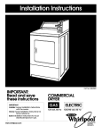
BURNER FLAME
It is recommended that a competent serviceman perform
these checks at the beginning of each heating season:
Start the furnace and let it operate about 10 minutes then ,
look at the burner flame. Flames should be soft and blue,
see Fig. 27. If flames appear abnormal, contact your gas
company.
a. Burner and Control Compartments
Keep clean at all times. Clean all foreign materials from
top of burner. For access to burner:
(1) Remove cabinet. (Reverse procedure outlined in
"Cabinet Installation".)
MAIN BURNER
(2) Shut off gas supply to furnace.
FLAME PATTERN
1111111111
Ill/llll/tlltl
(3) Remove six (6) #10-24 screws securing control
door assembly to heating element.
(4) Carefully
remove control
door and burner
assembly from heating element. Be careful not to
damage the control door gasket.
TOO MUCH /dR. CONES BRIGHT
BLUE AND REAL SHARP POINTS.
SOME33MES UFTING FROM PORTS
(5) After cleaning, replace control door and burner
assembly by reversing above procedure. Replace
the control door gasket if its condition is in doubt.
CORRECT
b. Motor and Blower
For maximum motor life of optional blower, the
manufacturer recommends the motor be inspected
yeady, dust blown out of the ventilating holes. Oil yearly
with SAE 20 high temp oil.
c. Vent System
INSUFFI'CIENT AJR, LONG OPEN
END CONES. YELLOW IN COLOR
Check vent cap and tube to be sure birds or children
have not blocked inlet air or flue openings. The flow
of combustion and ventilation air must not be
obstructed. Clean or replace before using furnace.
INN_ CONES UGHT BLUE POINTEDTOPj
OUTER MANTLE UGHT BLUE.
PROPER FLAME 1/2" TO 3/4 I' HIGH
d. Pilot Flame
See paragraph "ADJUST PILOT BURNER"
Start-Up Procedure, page 14, and Fig. 28.
under
TOP VIEW
e. Appliance Area
For better circulation and more effective heating, do
not place obstructive furniture closer than 4 feet to the
front of the cabinet or 2 feet to the side of the cabinet.
PILOT -
SIDE VIEW
BLUE FLAME
The appliance area must be kept clear and free from
combustible material, gasoline and other flammable
vapor and liquids.
3ENERATOR
f
DANGER OF BODILY INJURY OR DEATH.
TURN OFF ELECTRIC POWER SUPPLY AT
DISCONNECT SWITCH, FUSE BOX OR SERVICE
PANEL BEFORE REMOVING ANY DOORS OR ACCESS OR SERVICE PANELS FROM UNIT, IF
EQUIPPED WITH ACCESSORY BLOWER.
f.
ORANGE "rip
UGH1"
NAT,
GAS
S
WARNING
TYPICAL
.uE
CONE
END VIEW
CAST IRON BURNER
LP.G.
Cabinet Finish
Clean cabinet with damp rag. Never use abrasive
cleaners. Cabinets are finished in heat resistant baked enamel - DO NOT refinish with wall paint.
--20--
_NAT
BLUE CONE
.GAS
ICAL
END V1EW
CAST IRON BURNER
NAT. GAS
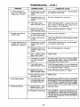
Troubleshooting
Gravity
Direct
Vent Wall Furnace
SYMPTOM
POSSIBLE CAUSE
CORRECTIVE ACTION
1. Pilot will not stay lit after
carefully following
lighting instructions.
A. Thermocouple or generator producing insufficient millivoltage.
Check pilot flame - must impinge on thermocoupie or generator. Be sure thermocouple or generator
is fully inserted in bracket. Make sure pilot lighting
door is tightly closed.
B. Loose or dirtythermocoupie or generator connections at gas valve.
Clean and/or tighten thermocouple
connections at valve.
C. Thermocouple or generator defective.
Check thermocouple with millivolt meter. Should
generate approximately 30 millivolts when not connected to load. When connected to load, should
generate approximately 14 millivolts; if below 7
millivolts, replace.
or generator
Check generator with millivolt meter. Take reading
at generator terminals of valve with pilot burning
and thermostat contacts closed. Should be 140
millivolts or more.
2. Pilot burning - no gas
to main burner.
3. Burner comes "On" but
goes "Off" after operating
for no apparent reason.
D. Grounded thermostat
lead wire (Wall thermostat model).
Remove thermostat lead wires from valve terminals.
If pilot now stays lit, trace thermostat wiring circuit
for a ground. May be grounded to furnace or gas
supply.
E. Thermomagnet pilot
safety defective.
Replace gas valve after above is checked out.
A. Manual valve not turned
to "On" position after
lighting pilot.
Turn gas valve knob to "On" position.
B. Temperature dial or thermostat not turned to a
position calling for heat.
Set temperature dial or thermostat to a position callirtg for heat.
C. Plugged burner orifice.
Check - clean or replace.
D Temperature dial out of
calibration. (Bulb control
model.)
See valve manufacturer's
E. Mis-wired or broken thermostat wires. Defective
thermostat. 0Nail thermostat model.
Check connections at valve terminals. Jumper
across thermostat terminals on valve - if valve
operates check thermostat wires.
F
See 1A above.
Pilot generator may not
be generating sufficient
millivoltage to open valve.
instructions.
G. Defective valve.
Replace.
A. Tubes not properly
installed.
Check vent tube and air inlet tube. Follow installation instructions. Be sure joints are tight and both
tubes are in place. Use only tubes furnished. Do
not extend tubes beyond original length.
B. Furnace may be
overrated.
Check for high pressure at valve - see rating plate
for specified minimax supply pressure. Check
burner orifice.
(continued next page)
g21--
Troubleshooting
... (cont.)
SYMPTOM
POSSIBLE CAUSE
CORRECTIVE ACTION
4, Furnace operates but
turns "Off" before room
temperature is attained.
A, Sensing bulb not located
properly. (Bulb control
model,)
Check location of sensing bulb - should be attached to back of control valve.
B. Temperature dial out of
calibration. (Bulb control
model.)
See valve manufacturer's
C. Thermostat location.
(Wall thermostat model.)
Check thermostat location - should not be in the
path of warm air discharge from furnace, near a
lamp, or above a "IIV. or stereo set.
D.
5. Furnace not producing
sufficient heat.
6. Furnace operates but will
not shut "Off" when room
temperature is attained.
7. Pilot outage problem.
8. Abnormal operation.
Defective thermostat.
(Wall thermostat model.)
instructions.
Check thermostat calibration or replace.
A. Furnace may be too small
for space being heated.
Check heat loss calculations.
B. Furnace not burning at
full rate.
Check for low gas pressure (see 3B page 21). Check
burner orifice.
A. Sensing bulb not located
properly. (Bulb control
model.)
Check location of sensing bulb - should be attached to back of control valve.
B. Temperature dial out of
calibration. (Bulb control
model.)
See valve manufacturer's instruction.
C. Bulb or capillary broken.
(Bulb control model.)
Replace valve.
D. Thermostat wiring defective. (Wall thermostat
model.)
Thermostat lead wires may be shorted together
caused by a nail or staple - check by removing thermostat leads from valve terminals.
E. Thermostat location.
(Wall thermostat model.)
Check thermostat location - if on an outside wall
or a hole in wall behind thermostat is causing cold
air to contact thermostat - relocate.
E Defective thermostat.
(Wall thermostat model.)
Check thermostat
G. Dirt under valve seat or
valve stuck open.
Replace valve.
A. Pilot flame may be low
or blowing (high) causing safety to drop out.
Adjust pilot flame. Check vent tube and air inlet tube
(see 3A page 21). Be sure pilot lighting door is closed. Pilot orifice or aerating hole may be plugged
(check for spiders, webs or other organic material).
A.
Delayed ignition - pilot
flame may be too low.
B. Expansion noise ticking.
--22--
calibration or replace.
Adjust pilot flame.
Check installation - casing may be distorted by being fastened to an uneven wall. Vent tube and air
inlet tube may be in a bind with vent cap assembly
- be sure hole through wall is correct and parts fit
without binding.
Williams
Direct
Vent Gas-Fired
REPLACEMENT
OPTIONAL
MODELS:
PARTS FOR
2205611;
2205612;
5005611;
500561
MANUFACTURE'S
2;
2302
2205621;
2205622
5005621;
5005622
AUTHORIZED
PART NO.
DESCRIPTION
1
6A24
SWITCH BRACKET
2
6B33
SWITCH BOX
3
P321017
SWITCH-PULL
4
P129700
SWITCH-AUTOMATIC
5
6A23
SWITCH BOX
6
P130600
MOTOR
7
6A93
MOTOR SUPPORT
8
P128400
VIBRATION
9
P130700
BLOWER WHEEL
6B64
BLOWER FRAME
10
Furnace
BLOWER ACCESSORY
USE ONLY
REF.
NO.
Wail
PARTS
CHAIN
COVER
ISOLATOR
(2
REQ'D)
NOTE: SCREWS AND BOLTS ARE STANDARD HARDWARE ITEMS, AVAILABLE LOCALLY.
--23---
Williams
Direct
Vent Gas-Fired
REPLACEMENT
1403611;
REF.
NO.
PARTS
1403612;
PART NO.
FOR MODELS:
1403621;
8C28
CASING
2
8A72
ELEMENT
3
8B61
COMBUSTION
4
P147001
FLUE TUBE
5
6B62
INNER
6
P14-7001
FLUE TUBE
7
P147000
AIR PAN
8
6054-1
AIR INLET
9
9306
VENT CAP
10
6C51
AIR INLET
11
8A85
FLUE
12
BB64
MOUNTING
SPACER
13
P121800
AIR INLET
GASKET
_t
1403622
DESCRIPTION
1
_,
Wall Furnace
WRAPPER
SHIELD
CHAMBER
GASKET
CASING
GASKET
GASKET
SHIELD
MAX.
COLLAR
(MAX.
EXTENSION
VENT
EXTENSION
KIT
9304
"A" FLUE EXTENSION
VENT
EXTENSION
KIT
9303
_"
FLUE
_tr
_
AIR INLET
AIR INLET
_
AIR INLET
'A" AIR INLET
9"
(MAX.
-
THICK
9"
9"
THICK
THICK
-
WALL
WALL)
PLATE
15 INCH
WITH
COLLAR - 15 INCH
SHIELD - 15 INCH
EXTENSION
WALL
24
INCH
COLLAR - 24 INCH
SHIELD - 24 INCH
(1)
WITH (1)
WITH (1)
WITH (1)
P147001
P147000
P147001
P147000
li_ NOT SHOWN
_NOT
AVAILABLE SEPARATELY (KIT FORM ONLY)
FOR PARTS ILLUSTRATION SEE PAGE 25
USE ONLY MANUFACllJRE'S
Au'rI-IORrZED PARTS,
NOTE: SCREWS AND BOLTS ARE STANDARD HARDWARE l'ID_S,
--24--
AVAIl.ABLE LOCALLY.
GASKET
GASKET
GASKET
GASKET
Williams
Direct
Vent Gas-Fired
Wall Furnace
REPLACEMENT PARTS
FOR MODELS:
1403611
1403621
; 140361 2
; 1403622
FOR
PARTS
lISTING
SEE
USE ONLY MANUFACTURER'S
--25 1
PAGE 24.
AUTHORIZED
PARTS
Service
Hints
If your furnace fails to work right, you may avoid inconvenience and the cost
of a service call by checking the following points before you call for service.
FOR
owner's
manual
SERVICE
YOUR
SAFETY
FOR
Do not store or use gasoline
or other flammable vapors and
liquids in the vicinity of this or any
other appliance
POSSIBLE CAUSE
YOUR
SAFETY
If you smell gas:
1. Open windows.
2. Don't touch electrical.
3. Extinguish any open flame.
4. Immediatelycallyourgassupplier.
WHAT TO DO
If your furnace is not heating or not giving enough heat --
MODEL
NOS.
1403612
NAT
1403622
NAT
2203612
NAT
2203622
NAT
3003612
NAT
3003622
NAT
1403611
LPG
Thermostat is not set correctly.
Pilot is out.
Reset thermostat to desired setting.
Check pilot. Relight if necessary following instructions for "Operating Your
Furnace".
Pilot is on but burner
on.
If gas valve is set at other than "On"
furnace will not operate. Shut furnace
down and following instructions for
relighting in "Operating Your Furnace"
section.
won't come
Burner is not operating properly.
Check flame. If it is yellow, the burner
is not getting enough air. Or if flame is
blue and noisy and seems to lift off the
burner, the burner is getting too much
air. See "Checks and Adjustments",
page 14.
Air flow restricted
Check that doors, drapes or furniture
are not blocking louvers.
1403621LPG
2203611LPG
2203621LPG
3003611LPG
3003621LPG
NOTE: CANADIAN MODEL NUMBERS THIRD
DIGIT FROM LEFT TO BE:
1 FOR BASIC ALTITUDE
2 FOR HIGH ALTITUDE
EXAMPLE:
MODEL 1403612 BECOMES 1413612
(0-2000 FT BASIC ALTITUDE)
OR BECOMES 1423612
(2000-4000
FT. HIGH ALTITUDE)
Pilot goes out time after time -Furnace flue blocked.
Pilot and burner access door not
closed properly.
If burner is noisy -Gas input amount is incorrect.
Too much primary air.
If blower does not run -Fuse is blown.
Blower not connected to electric
power.
If blower motor is noisy -Housing rattling.
Blower dirty.
Blower wheel bent.
See troubleshooting
How to Order
When ordering repair parts, always give the following
information:
1. MODELNUMBER
2.
MFG.DATECODE
3. PART NUMBER
4. PART DESCRIPTION
Locate vent outlet blockage and clean.
Check the door. See section on
"Operating Your Furnace" beginning
on page 15.
Contact Williams Service Department.
Contact Williams Service Department.
Replace fuse.
Connect to electric power.
Tighten screws.
Clean blower wheel.
Straighten or replace.
section for more detailed information.
Repair
Parts
All parts listed herein may be ordered from your equipment supplier.
The Model Number of your Williams wall furnace will be
found on the rating plate near gas valve, inside control
compartment.
WILLIAMS
FURNACE COMPANY
225 Acacia Street
Colton, CA 92324 USA
(909)
© 1997
The Williams Furnace Company
Rev. 5/97
825-0993
Printed in U.S.A.
MANUFACTURED
IN THE U.S.A.
Established 1916
FAX: (909) 824-8009
P322256