1
AIR CONDITIONING—631
CHRYSLER SERVICE MANUAL
Section XVII
CHRYSLER AIR CONDITIONING
SYSTEM
1. GENERAL INFORMATION
The occupants of an air conditioned car may
select the temperature and volume of the air
that is circulating in the car interior that will
provide them with the most comfort.
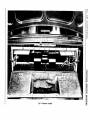
In addition to the conditioned air that is recirculating in the car (Fig. 1), scoops pick up fresh
air from the outside, bring it through ducts into
the evaporator, where it joins with the circulating air.
With the blower operating at high speed, more
than 300 cu. ft. per minute of cool air is forced
into the car. Approximately % of this is outside
air. This will give a complete change of all the
air in the car every li/ 2 minutes.
By providing this complete change of filtered
air in air conditioned cars every li/2 minutes, it
is unnecessary to open the car windows in either
winter or summer. This greatly reduces road
noises and keeps out practically all dirt, when
driving in dusty areas.
Three blower speeds are provided with each
of the two cooling conditions. Low, Medium and
High in the Cold, or full capacity cooling position. Low, Medium and High in the Cool, or
Moderate cooling position. A choice of the three
blower speeds for circulating air without the air
being cooled by the air conditioning unit is also
provided.
The refrigerant used in the Air Conditioning
System is Freon 12.
AIR CONDITIONING SYSTEM COMPONENTS
2. COMPRESSOR
The compressor, as shown in Figure 12, is a two
cylinder reciprocating type unit with a speed of
approximately 935 rpm. at 25 mph.
3. COMPRESSOR LUBRICATION
Lubrication is by a combination of splash and
centrifugal pressure. As the rods, counterweights and slinger rotate through the oil in the
crankcase it is picked up and thrown over the
interior of the crankcase. The rear main bearing
is lubricated by this splash and the connecting
rods are partially splash lubricated.
In addition to the splash lubrication, oil is
thrown into cavities in both bearing retainer
plates. As the shaft rotates, a pressure is built
up on the oil in the rear bearing retainer cavity
and the oil is forced through the rifle drilled
crankshaft. Transverse passages are drilled
through the shaft and supply oil to the connecting rod bearings, the piston pins and the shaft
seal.
The front main bearing is lubricated from the
oil in the front bearing retainer plate oil cavity.
4. COMPRESSOR VALVES
The discharge and suction valves, as shown in
Figures 2 and 3, are inertia type Reed Valves