1
634—AIR CONDITIONING
11. OIL LEVEL
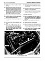
An access plug is provided in the crankcase for
the purpose of measuring the height of the oil in
the crankcase. (See Fig. 12.) A new compressor
before installation contains 12 ounces of oil and
is charged with dry air, however, due to some of
the oil being picked up and entrained in the
system, the crankcase does not contain 12 ounces
of oil after it is in service.
The proper height of the oil in the compressor
after it is in service should not exceed % inch to
one inch as measured on a dip stick inserted
through the access hole. A sight glass is provided to indicate that oil is present, but does not
tell how much.
12. SERVICE VALVES
Due to the fact that it may be necessary to remove the compressor for compressor or engine
service and also to provide means for connecting test equipment, two service valves are
provided.
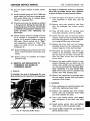
The suction service valve is attached to the
inlet side of the compressor, as shown in Figure
4. The discharge service valve is connected in the
discharge tube at the inlet side of the condenser.
(See Fig. 3.)
Rotating the valve stems clockwise until the
valves are fully seated, front seats the valve and
isolates the compressor from the system. Rotating the valve stem clockwise from the back-seat
position also opens the service port to supply
pressure to the gauges. Rotating the valve stems
counter-clockwise, back seats the valves and is
the operating position.
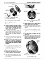
13. MAGNETIC CLUTCH
The magnetic clutch shown in Figure 20, is provided in the compressor drive pulley. The clutch
consists of a spring loaded drive plate that is
attached to the compressor crankshaft. The
electro-magnet coil is mounted in the pulley with
the ends of the coil connected to separate brush
or collector rings. Hinged type brush holders
hold the brushes against the collector rings.
When the electro-magnet is not energized the
pulley assembly free-wheels on a double roll ball
bearing. When the electro-magnet is energized
the plate is magnetically attracted to the electro-
CHRYSLER SERVICE MANUAL
magnet and the compressor crankshaft is then
coupled to the drive pulley.
The magnetic clutch can be engaged at any
engine speed without damage. A sintered iron
brake shoe, impregnated with fibrous material
is bonded to the drive plate to reduce chatter
and wear during engagement.
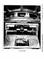
14. EVAPORATOR
The evaporator unit, shown in Figure 2, contains an evaporator wherein the liquid refrigerant vaporizes due to the heat which it absorbs
from the air passing over the evaporator tube
fins. This absorption of heat from the air results
in a considerable reduction in the air temperature. It is located in the luggage compartment
and contains the expansion valve and evaporator coil which is connected by tubing from the
expansion valve to the compressor. The unit also
contains the motor and blower assembly.
15. BLOWER SYSTEM
The blower motor and fans are located in the
evaporator. The blower motor has three speeds;
low, medium and high. The speeds are controlled
through the blower switch located on the instrument panel.
16. SOLENOID VALVE
The solenoid valve is connected into a by-pass
line between the high pressure side of the compressor and the inlet side of the evaporator at
the distributor. The normal position of the valve
is open.
With the blower switch on and the temperature control switch in the "Cool" position, the
valve is not electrically energized and is therefore open. With the valve open, gasflowsthrough
the by-pass line and into the evaporator, mixing
with the liquid refrigerant from the expansion
valve. The amount of heat absorbed from the
air by the evaporator is decreased and the temperature of the car interior will be moderately
cooled.
Rotation of the temperature control to the
"Cold" position completes the electrical circuit to
the solenoid windings, which energizes the solenoid and closes the valve. The flow of hot gas
through the by-pass line is cut-off and the system
can then operate at full capacity.