1
A 2000
®
ULTRAFEED
VARIAC CONTROLLED
WIRE FEEDER
Art # A-07354
Service Manual
Version No: AC.01
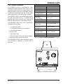
Operating Features:
Issue Date: May 30, 2006
V
50 HZ
60
Manual No.: 0-4893B
650
IPM
WARNINGS
Read and understand this entire Manual and your employer’s safety practices before installing,
operating, or servicing the equipment.
While the information contained in this Manual represents the Manufacturer's best judgement,
the Manufacturer assumes no liability for its use.
Ultrafeed A 2000 Wire Feeder
Service Manual Number 0-4893B for:
Part # W3200001
Published by:
Thermadyne Industries
82 Benning Street
West Lebanon, New Hampshire, USA 03784
(603) 298-5711
www.thermalarc.com
Copyright 2006 by
Thermadyne Industries
All rights reserved.
Reproduction of this work, in whole or in part, without written permission of the publisher is prohibited.
The publisher does not assume and hereby disclaims any liability to any party for any
loss or damage caused by any error or omission in this Manual, whether such error
results from negligence, accident, or any other cause.
Publication Date: May 30, 2006
Record the following information for Warranty purposes:
Where Purchased:
___________________________________
Purchase Date:
___________________________________
Equipment Serial #:
___________________________________
i
TABLE OF CONTENTS
SECTION 1:
SAFETY INSTRUCTIONS AND WARNINGS ....................................................... 1-1
1.01
1.02
1.03
1.04
1.05
1.06
Arc Welding Hazards ...................................................................................... 1-1
Principal Safety Standards ............................................................................. 1-4
Precautions De Securite En Soudage A L’arc .................................................. 1-5
Dangers relatifs au soudage à l’arc ................................................................. 1-5
Principales Normes De Securite ..................................................................... 1-8
Declaration Of Conformity .............................................................................. 1-9
SECTION 2:
INTRODUCTION ...................................................................................... 2-1
2.01
2.02
2.03
2.04
2.05
2.06
How To Use This Manual ................................................................................ 2-1
Equipment Identification................................................................................. 2-1
Symbol Chart ................................................................................................. 2-2
General Information ....................................................................................... 2-3
Features and Benefits ..................................................................................... 2-4
Options and Accessories ................................................................................ 2-4
SECTION 3:
INSTALLATION ....................................................................................... 3-1
3.01
3.02
3.03
3.04
3.05
3.06
3.07
3.08
3.09
Connections ................................................................................................... 3-1
Grounding ...................................................................................................... 3-1
EMI Considerations ........................................................................................ 3-1
Installation Of Welding Wire Spool ................................................................. 3-2
Adjustment Of Spool Tension ......................................................................... 3-2
Input And Output Wire Guide Installation ....................................................... 3-3
Selection And Installation Of Feed Rolls ......................................................... 3-4
Welding Gun Compatibility And Installation ................................................... 3-5
Threading Wire Into Feedhead ........................................................................ 3-6
SECTION 4:
OPERATION ........................................................................................... 4-1
4.01 Prewelding Procedure .................................................................................... 4-1
4.02 Front Panel ..................................................................................................... 4-1
4.03 Rear Panel Controls &Connections ................................................................ 4-2
4.04 Feedhead Components ................................................................................... 4-3
4.05 Power Source Compatibility ........................................................................... 4-4
4.06 Power Source Compatability Details ............................................................... 4-4
TABLETABLE
OF CONTENTS
OF CONTENTS
(continued)
SECTION 5:
Maintenance ......................................................................................... 5-1
5.01
5.02
5.03
5.04
5.05
Cleaning The Unit ........................................................................................... 5-1
Cleaning The Feed Rolls ................................................................................. 5-1
Feedhead Maintenance ................................................................................... 5-1
System Maintenance ...................................................................................... 5-1
Gas Valve Maintenance................................................................................... 5-2
SECTION 6:
TROUBLESHOOTING ................................................................................ 6-1
6.01 Troubleshooting Hints .................................................................................... 6-1
6.02 Troubleshooting Guide ................................................................................... 6-1
SECTION 7:
PARTS LIST .......................................................................................... 7-1
7.01
7.02
7.03
7.04
7.05
7.06
Equipment Identification................................................................................. 7-1
How To Use This Parts List ............................................................................ 7-1
External Components and Labels ................................................................... 7-2
Electrical Components .................................................................................... 7-4
Feedhead Components ................................................................................... 7-6
Feed Drive Motor ............................................................................................ 7-8
APPENDIX 1: FEED ROLL KITS ........................................................................... A-1
APPENDIX 2: OPTIONS AND ACCESSORIES ........................................................... A-2
APPENDIX 3: SYSTEM OUTLINE ......................................................................... A-3
APPENDIX 4: WIRE DIAGRAM ........................................................................... A-4
LIMITED WARRANTY
WARRANTY SCHEDULE
GLOBAL CUSTOMER SERVICE CONTACT INFORMATION .......................... Inside Rear Cover
ULTRAFEED A 2000
SECTION 1:
SAFETY INSTRUCTIONS AND WARNINGS
!
WARNING
PROTECT YOURSELF AND OTHERS FROM POSSIBLE SERIOUS INJURY OR DEATH. KEEP CHILDREN AWAY. PACEMAKER WEARERS KEEP
AWAY UNTIL CONSULTING YOUR DOCTOR. DO NOT LOSE THESE INSTRUCTIONS. READ OPERATING/INSTRUCTION MANUAL BEFORE
INSTALLING, OPERATING OR SERVICING THIS EQUIPMENT.
Welding products and welding processes can cause serious injury or death, or damage to other equipment or property, if the operator does not
strictly observe all safety rules and take precautionary actions.
Safe practices have developed from past experience in the use of welding and cutting. These practices must be learned through study and
training before using this equipment. Some of these practices apply to equipment
connected to power lines; other practices apply to engine driven equipment. Anyone not having extensive
training in welding and cutting practices should not attempt to weld.
Safe practices are outlined in the American National Standard Z49.1 entitled: SAFETY IN WELDING AND CUTTING. This publication and other
guides to what you should learn before operating this equipment are listed at the end of these safety precautions. HAVE ALL INSTALLATION,
OPERATION, MAINTENANCE, AND REPAIR WORK PERFORMED ONLY BY QUALIFIED PEOPLE.
1.01
Arc Welding Hazards
7. Use fully insulated electrode holders. Never dip holder in water to
cool it or lay it down on the ground or the work surface. Do not
touch holders connected to two welding machines at the same
time or touch other people with the holder or electrode.
8. Do not use worn, damaged, undersized, or poorly spliced cables.
WARNING
9. Do not wrap cables around your body.
10. Ground the workpiece to a good electrical (earth) ground.
ELECTRIC SHOCK can kill.
11. Do not touch electrode while in contact with the work (ground)
circuit.
Touching live electrical parts can cause fatal shocks or
severe burns. The electrode and work circuit is electrically
live whenever the output is on. The input power circuit
and machine internal circuits are also live when power
is on. In semiautomatic or automatic wire welding, the
wire, wire reel, drive roll housing, and all metal parts
touching the welding wire are electrically live. Incorrectly
installed or improperly grounded equipment is a hazard.
12. Use only well-maintained equipment. Repair or replace damaged
parts at once.
1. Do not touch live electrical parts.
13. In confined spaces or damp locations, do not use a welder with
AC output unless it is equipped with a voltage reducer. Use
equipment with DC output.
14. Wear a safety harness to prevent falling if working above floor
level.
15. Keep all panels and covers securely in place.
2. Wear dry, hole-free insulating gloves and body protection.
3. Insulate yourself from work and ground using dry insulating mats
or covers.
4. Disconnect input power or stop engine before installing or
servicing this equipment. Lock input power disconnect switch
open, or remove line fuses so power cannot be turned on
accidentally.
5. Properly install and ground this equipment according to its Owner’s
Manual and national, state, and local codes.
6. Turn off all equipment when not in use. Disconnect power to
equipment if it will be left unattended or out of service.
WARNING
ARC RAYS can burn eyes and skin; NOISE can damage
hearing. Arc rays from the welding process produce
intense heat and strong ultraviolet rays that can burn
eyes and skin. Noise from some processes can damage
hearing.
1. Wear a welding helmet fitted with a proper shade of filter (see
ANSI Z49.1 listed in Safety Standards) to protect your face and
eyes when welding or watching.
2. Wear approved safety glasses. Side shields recommended.
May 30, 2006
1-1
ULTRAFEED A 2000
3. Use protective screens or barriers to protect others from flash
and glare; warn others not to watch the arc.
WARNING
4. Wear protective clothing made from durable, flame-resistant
material (wool and leather) and foot protection.
WELDING can cause fire or explosion.
5. Use approved ear plugs or ear muffs if noise level is high.
Sparks and spatter fly off from the welding arc. The flying
sparks and hot metal, weld spatter, hot workpiece, and
hot equipment can cause fires and burns. Accidental
contact of electrode or welding wire to metal objects
can cause sparks, overheating, or fire.
WARNING
FUMES AND GASES can be hazardous to your health.
1. Protect yourself and others from flying sparks and hot metal.
Welding produces fumes and gases. Breathing these
fumes and gases can be hazardous to your health.
2. Do not weld where flying sparks can strike flammable material.
1. Keep your head out of the fumes. Do not breath the fumes.
3. Remove all flammables within 35 ft (10.7 m) of the welding arc.
If this is not possible, tightly cover them with approved covers.
2. If inside, ventilate the area and/or use exhaust at the arc to remove
welding fumes and gases.
4. Be alert that welding sparks and hot materials from welding can
easily go through small cracks and openings to adjacent areas.
3. If ventilation is poor, use an approved air-supplied respirator.
5. Watch for fire, and keep a fire extinguisher nearby.
4. Read the Material Safety Data Sheets (MSDSs) and the
manufacturer’s instruction for metals, consumables, coatings, and
cleaners.
6. Be aware that welding on a ceiling, floor, bulkhead, or partition
can cause fire on the hidden side.
5. Work in a confined space only if it is well ventilated, or while
wearing an air-supplied respirator. Shielding gases used for
welding can displace air causing injury or death. Be sure the
breathing air is safe.
6. Do not weld in locations near degreasing, cleaning, or spraying
operations. The heat and rays of the arc can react with vapors to
form highly toxic and irritating gases.
7. Do not weld on closed containers such as tanks or drums.
8. Connect work cable to the work as close to the welding area as
practical to prevent welding current from traveling long, possibly
unknown paths and causing electric shock and fire hazards.
9. Do not use welder to thaw frozen pipes.
10. Remove stick electrode from holder or cut off welding wire at
contact tip when not in use.
7. Do not weld on coated metals, such as galvanized, lead, or
cadmium plated steel, unless the coating is removed from the
weld area, the area is well ventilated, and if necessary, while
wearing an air-supplied respirator. The coatings and any metals
containing these elements can give off toxic fumes if welded.
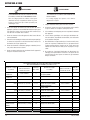
Eye protection filter shade selector for welding or cutting
(goggles or helmet), from AWS A6.2-73.
Welding or cutting
Torch soldering
Torch brazing
Oxygen Cutting
Light
Medium
Heavy
Gas welding
Light
Medium
Heavy
Shielded metal-arc
1-2
Electrode Size
Filter
2
3 or 4
Under 1 in., 25 mm
1 to 6 in., 25-150 mm
Over 6 in., 150 mm
3 or 4
4 or 5
5 or 6
Under 1/8 in., 3 mm
1/8 to 1/2 in., 3-12 mm
Over 1/2 in., 12 mm
Under 5/32 in., 4 mm
5/32 to 1/4 in.,
Over 1/4 in., 6.4 mm
4 or 5
5 or 6
6 or 8
10
12
14
Welding or cutting
Electrode Size
Gas metal-arc
Non-ferrous base metal
All
Ferrous base metal
All
Gas tungsten arc welding
All
(TIG)
All
Atomic hydrogen welding
All
Carbon arc welding
All
Plasma arc welding
Carbon arc air gouging
Light
Heavy
Plasma arc cutting
Light Under 300 Amp
Medium 300 to 400 Amp
Heavy Over 400 Amp
Filter
11
12
12
12
12
12
12
14
9
12
14
May 30, 2006
ULTRAFEED A 2000
WARNING
FLYING SPARKS AND HOT METAL can cause injury.
Chipping and grinding cause flying metal. As welds cool,
they can throw off slag.
1. Wear approved face shield or safety goggles. Side shields
recommended.
2. Wear proper body protection to protect skin.
WARNING
2. If used in a closed area, vent engine exhaust outside and away
from any building air intakes.
WARNING
ENGINE FUEL can cause fire or explosion.
Engine fuel is highly flammable.
1. Stop engine before checking or adding fuel.
2. Do not add fuel while smoking or if unit is near any sparks or
open flames.
3. Allow engine to cool before fueling. If possible, check and add
fuel to cold engine before beginning job.
CYLINDERS can explode if damaged.
4. Do not overfill tank — allow room for fuel to expand.
Shielding gas cylinders contain gas under high pressure.
If damaged, a cylinder can explode. Since gas cylinders
are normally part of the welding process, be sure to treat
them carefully.
5. Do not spill fuel. If fuel is spilled, clean up before starting engine.
1. Protect compressed gas cylinders from excessive heat, mechanical
shocks, and arcs.
WARNING
MOVING PARTS can cause injury.
2. Install and secure cylinders in an upright position by chaining
them to a stationary support or equipment cylinder rack to prevent
falling or tipping.
Moving parts, such as fans, rotors, and belts can cut fingers and hands
and catch loose clothing.
3. Keep cylinders away from any welding or other electrical circuits.
1. Keep all doors, panels, covers, and guards closed and
securely in place.
4. Never allow a welding electrode to touch any cylinder.
2. Stop engine before installing or connecting unit.
5. Use only correct shielding gas cylinders, regulators, hoses, and
fittings designed for the specific application; maintain them and
associated parts in good condition.
3. Have only qualified people remove guards or covers for
maintenance and troubleshooting as necessary.
6. Turn face away from valve outlet when opening cylinder valve.
4. To prevent accidental starting during servicing, disconnect
negative (-) battery cable from battery.
7. Keep protective cap in place over valve except when cylinder is in
use or connected for use.
5. Keep hands, hair, loose clothing, and tools away from moving
parts.
8. Read and follow instructions on compressed gas cylinders,
associated equipment, and CGA publication P-1 listed in Safety
Standards.
6. Reinstall panels or guards and close doors when servicing
is finished and before starting engine.
!
WARNING
Engines can be dangerous.
WARNING
SPARKS can cause BATTERY GASES TO EXPLODE;
BATTERY ACID can burn eyes and skin.
Batteries contain acid and generate explosive gases.
WARNING
1. Always wear a face shield when working on a battery.
2. Stop engine before disconnecting or connecting battery cables.
ENGINE EXHAUST GASES can kill.
3. Do not allow tools to cause sparks when working on a battery.
Engines produce harmful exhaust gases.
4. Do not use welder to charge batteries or jump start vehicles.
1. Use equipment outside in open, well-ventilated areas.
5. Observe correct polarity (+ and –) on batteries.
May 30, 2006
1-3
ULTRAFEED A 2000
1.02
WARNING
STEAM AND PRESSURIZED HOT COOLANT can burn
face, eyes, and skin.
The coolant in the radiator can be very hot and under
pressure.
1. Do not remove radiator cap when engine is hot. Allow engine to
cool.
2. Wear gloves and put a rag over cap area when removing cap.
3. Allow pressure to escape before completely removing cap.
!
WARNING
This product, when used for welding or cutting, produces
fumes or gases which contain chemicals know to the
State of California to cause birth defects and, in some
cases, cancer. (California Health & Safety code Sec.
25249.5 et seq.)
NOTE
Principal Safety Standards
Safety in Welding and Cutting, ANSI Standard Z49.1, from American
Welding Society, 550 N.W. LeJeune Rd., Miami, FL 33126.
Safety and Health Standards, OSHA 29 CFR 1910, from Superintendent
of Documents, U.S. Government Printing Office, Washington, D.C.
20402.
Recommended Safe Practices for the Preparation for Welding and
Cutting of Containers That Have Held Hazardous Substances, American
Welding Society Standard AWS F4.1, from American Welding Society,
550 N.W. LeJeune Rd., Miami, FL 33126.
National Electrical Code, NFPA Standard 70, from National Fire
Protection Association, Batterymarch Park, Quincy, MA 02269.
Safe Handling of Compressed Gases in Cylinders, CGA Pamphlet P1, from Compressed Gas Association, 1235 Jefferson Davis Highway,
Suite 501, Arlington, VA 22202.
Code for Safety in Welding and Cutting, CSA Standard W117.2, from
Canadian Standards Association, Standards Sales, 178 Rexdale
Boulevard, Rexdale, Ontario, Canada M9W 1R3.
Safe Practices for Occupation and Educational Eye and Face Protection,
ANSI Standard Z87.1, from American National Standards Institute,
1430 Broadway, New York, NY 10018.
Cutting and Welding Processes, NFPA Standard 51B, from National
Fire Protection Association, Batterymarch Park, Quincy, MA 02269.
Considerations About Welding And The Effects of Low
Frequency Electric and Magnetic Fields
The following is a quotation from the General Conclusions Section of
the U.S. Congress, Office of Technology Assessment, Biological Effects
of
Power
Frequency Electric & Magnetic Fields - Background Paper, OTA-BP-E63 (Washington, DC: U.S. Government Printing Office, May 1989):
“...there is now a very large volume of scientific findings based on
experiments at the cellular level and from studies with animals and
people which clearly establish that low frequency magnetic fields and
interact with, and produce changes in, biological systems. While most
of this work is of very high quality, the results are complex. Current
scientific understanding does not yet allow us to interpret the evidence
in a single coherent framework. Even more frustrating, it does not yet
allow us to draw definite conclusions about questions of possible risk
or to offer clear science-based advice on strategies to minimize or
avoid potential risks.”
To reduce magnetic fields in the workplace, use the following
procedures.
1. Keep cables close together by twisting or taping them.
2. Arrange cables to one side and away from the operator.
3. Do not coil or drape cable around the body.
4. Keep welding power source and cables as far away from
body as practical.
ABOUT PACEMAKERS:
The above procedures are among those also normally
recommended for pacemaker wearers. Consult your
doctor for complete information.
1-4
May 30, 2006
ULTRAFEED A 2000
1.03
Precautions De Securite En Soudage A L’arc
!
MISE EN GARDE
LE SOUDAGE A L’ARC EST DANGEREUX
PROTEGEZ-VOUS, AINSI QUE LES AUTRES, CONTRE LES BLESSURES GRAVES POSSIBLES OU LA MORT. NE LAISSEZ PAS LES ENFANTS
S’APPROCHER, NI LES PORTEURS DE STIMULATEUR CARDIAQUE (A MOINS QU’ILS N’AIENT CONSULTE UN MEDECIN). CONSERVEZ CES
INSTRUCTIONS. LISEZ LE MANUEL D’OPERATION OU LES INSTRUCTIONS AVANT D’INSTALLER, UTILISER OU ENTRETENIR CET EQUIPEMENT.
Les produits et procédés de soudage peuvent sauser des blessures graves ou la mort, de même que des dommages au reste du matériel et à la
propriété, si l’utilisateur n’adhère pas strictement à toutes les règles de sécurité et ne prend pas les précautions nécessaires.
En soudage et coupage, des pratiques sécuritaires se sont développées suite à l’expérience passée. Ces pratiques doivent être apprises par
étude ou entraînement avant d’utiliser l’equipement. Toute personne n’ayant pas suivi un entraînement intensif en soudage et coupage ne devrait
pas tenter de souder. Certaines pratiques concernent les équipements raccordés aux lignes d’alimentation alors que d’autres s’adressent aux
groupes électrogènes.
La norme Z49.1 de l’American National Standard, intitulée “SAFETY IN WELDING AND CUTTING” présente les pratiques sécuritaires à suivre.
Ce document ainsi que d’autres guides que vous devriez connaître avant d’utiliser cet équipement sont présentés à la fin de ces instructions de
sécurité.
SEULES DES PERSONNES QUALIFIEES DOIVENT FAIRE DES TRAVAUX D’INSTALLATION, DE REPARATION, D’ENTRETIEN ET D’ESSAI.
1.04
Dangers relatifs au soudage à l’arc
AVERTISSEMENT
L’ELECTROCUTION PEUT ETRE MORTELLE.
6. Arrêtez tout équipement après usage. Coupez l’alimentation de
l’équipement s’il est hors d’usage ou inutilisé.
7. N’utilisez que des porte-électrodes bien isolés. Ne jamais plonger
les porte-électrodes dans l’eau pour les refroidir. Ne jamais les
laisser traîner par terre ou sur les pièces à souder. Ne touchez
pas aux porte-électrodes raccordés à deux sources de courant en
même temps. Ne jamais toucher quelqu’un d’autre avec l’électrode
ou le porte-électrode.
8. N’utilisez pas de câbles électriques usés, endommagés, mal
épissés ou de section trop petite.
9. N’enroulez pas de câbles électriques autour de votre corps.
Une décharge électrique peut tuer ou brûler gravement.
L’électrode et le circuit de soudage sont sous tension
dès la mise en circuit. Le circuit d’alimentation et les
circuits internes de l’équipement sont aussi sous tension dès la mise en marche. En soudage automatique
ou semi-automatique avec fil, ce dernier, le rouleau ou
la bobine de fil, le logement des galets d’entrainement
et toutes les pièces métalliques en contact avec le fil de
soudage sont sous tension. Un équipement
inadéquatement installé ou inadéquatement mis à la terre
est dangereux.
10. N’utilisez qu’une bonne prise de masse pour la mise à la terre de
la pièce à souder.
11. Ne touchez pas à l’électrode lorsqu’en contact avec le circuit de
soudage (terre).
12. N’utilisez que des équipements en bon état. Réparez ou remplacez
aussitôt les pièces endommagées.
13. Dans des espaces confinés ou mouillés, n’utilisez pas de source
de courant alternatif, à moins qu’il soit muni d’un réducteur de
tension. Utilisez plutôt une source de courant continu.
14. Portez un harnais de sécurité si vous travaillez en hauteur.
1. Ne touchez pas à des pièces sous tension.
15. Fermez solidement tous les panneaux et les capots.
2. Portez des gants et des vêtements isolants, secs et non troués.
3
Isolez-vous de la pièce à souder et de la mise à la terre au moyen
de tapis isolants ou autres.
4. Déconnectez la prise d’alimentation de l’équipement ou arrêtez le
moteur avant de l’installer ou d’en faire l’entretien. Bloquez le
commutateur en circuit ouvert ou enlevez les fusibles de
l’alimentation afin d’éviter une mise en marche accidentelle.
5. Veuillez à installer cet équipement et à le mettre à la terre selon le
manuel d’utilisation et les codes nationaux, provinciaux et locaux
applicables.
May 30, 2006
1-5
ULTRAFEED A 2000
AVERTISSEMENT
AVERTISSEMENT
LE RAYONNEMENT DE L’ARC PEUT BRÛLER LES YEUX
ET LA PEAU; LE BRUIT PEUT ENDOMMAGER L’OUIE.
LES VAPEURS ET LES FUMEES SONT DANGEREUSES
POUR LA SANTE.
L’arc de soudage produit une chaleur et des rayons
ultraviolets intenses, susceptibles de brûler les yeux et
la peau. Le bruit causé par certains procédés peut
endommager l’ouïe.
Le soudage dégage des vapeurs et des fumées
dangereuses à respirer.
1. Eloignez la tête des fumées pour éviter de les respirer.
1. Portez une casque de soudeur avec filtre oculaire de nuance
appropriée (consultez la norme ANSI Z49 indiquée ci-après) pour
vous protéger le visage et les yeux lorsque vous soudez ou que
vous observez l’exécution d’une soudure.
2. A l’intérieur, assurez-vous que l’aire de soudage est bien ventilée
ou que les fumées et les vapeurs sont aspirées à l’arc.
2. Portez des lunettes de sécurité approuvées. Des écrans latéraux
sont recommandés.
4. Lisez les fiches signalétiques et les consignes du fabricant relatives aux métaux, aux produits consummables, aux revêtements
et aux produits nettoyants.
3. Entourez l’aire de soudage de rideaux ou de cloisons pour protéger
les autres des coups d’arc ou de l’éblouissement; avertissez les
observateurs de ne pas regarder l’arc.
4. Portez des vêtements en matériaux ignifuges et durables (laine et
cuir) et des chaussures de sécurité.
5. Portez un casque antibruit ou des bouchons d’oreille approuvés
lorsque le niveau de bruit est élevé.
3. Si la ventilation est inadequate, portez un respirateur à adduction
d’air approuvé.
5. Ne travaillez dans un espace confiné que s’il est bien ventilé; sinon,
portez un respirateur à adduction d’air. Les gaz protecteurs de
soudage peuvent déplacer l’oxygène de l’air et ainsi causer des
malaises ou la mort. Assurez-vous que l’air est propre à la respiration.
6. Ne soudez pas à proximité d’opérations de dégraissage, de
nettoyage ou de pulvérisation. La chaleur et les rayons de l’arc
peuvent réagir avec des vapeurs et former des gaz hautement
toxiques et irritants.
SELECTION DES NUANCES DE FILTRES OCULAIRS POUR LA PROTECTION
DES YEUX EN COUPAGE ET SOUDAGE (selon AWS á 8.2-73)
Dimension d'électrode ou
Epiasseur de métal ou
Intensité de courant
Nuance de
filtre oculaire
Brassage tendre
au chalumeau
toutes conditions
2
Brassage fort
au chalumeau
toutes conditions
3 ou 4
Opération de coupage
ou soudage
Soudage á l'arc sous gaz
avec fil plein (GMAW)
métaux non-ferreux
toutes conditions
11
métaux ferreux
toutes conditions
12
toutes conditions
12
toutes conditions
12
toutes conditions
12
toutes dimensions
12
Oxycoupage
mince
moins de 1 po. (25 mm)
moyen de 1 á 6 po. (25 á 150 mm)
épais
plus de 6 po. (150 mm)
2 ou 3
4 ou 5
5 ou 6
Soudage aux gaz
Dimension d'électrode ou
Nuance de
Epiasseur de métal ou
filtre oculaire
Intensité de courant
Opération de coupage
ou soudage
Soudage á l'arc sous gaz avec
électrode de tungstène (GTAW)
Soudage á l'hydrogène
atomique (AHW)
Soudage á l'arc avec
électrode de carbone (CAW)
Soudage á l'arc Plasma (PAW)
mince
moins de 1/8 po. (3 mm)
moyen de 1/8 á 1/2 po. (3 á 12 mm)
épais
Soudage á l'arc avec
électrode enrobees
(SMAW)
4 ou 5
Gougeage Air-Arc avec
électrode de carbone
5 ou 6
mince
12
plus de 1/2 po. (12 mm)
6 ou 8
épais
14
moins de 5/32 po. (4 mm)
10
5/32 á 1/4 po. (4 á 6.4 mm)
12
mince
moins de 300 amperès
9
plus de 1/4 po. (6.4 mm)
14
moyen
de 300 á 400 amperès
12
plus de 400 amperès
14
Coupage á l'arc Plasma (PAC)
épais
1-6
May 30, 2006
ULTRAFEED A 2000
7. Ne soudez des tôles galvanisées ou plaquées au plomb ou au
cadmium que si les zones à souder ont été grattées à fond, que si
l’espace est bien ventilé; si nécessaire portez un respirateur à adduction d’air. Car ces revêtements et tout métal qui contient ces
éléments peuvent dégager des fumées toxiques au moment du
soudage.
AVERTISSEMENT
AVERTISSEMENT
LES ETINCELLES ET LES PROJECTIONS BRULANTES
PEUVENT CAUSER DES BLESSURES.
Le piquage et le meulage produisent des particules
métalliques volantes. En refroidissant, la soudure peut
projeter du éclats de laitier.
LE SOUDAGE PEUT CAUSER UN INCENDIE OU UNE
EXPLOSION
1. Portez un écran facial ou des lunettes protectrices
approuvées. Des écrans latéraux sont recommandés.
L’arc produit des étincellies et des projections. Les
particules volantes, le métal chaud, les projections de
soudure et l’équipement surchauffé peuvent causer un
incendie et des brûlures. Le contact accidentel de
l’électrode ou du fil-électrode avec un objet métallique
peut provoquer des étincelles, un échauffement ou un
incendie.
2. Portez des vêtements appropriés pour protéger la peau.
1. Protégez-vous, ainsi que les autres, contre les étincelles et du
métal chaud.
2. Ne soudez pas dans un endroit où des particules volantes ou des
projections peuvent atteindre des matériaux inflammables.
3. Enlevez toutes matières inflammables dans un rayon de 10, 7
mètres autour de l’arc, ou couvrez-les soigneusement avec des
bâches approuvées.
4. Méfiez-vous des projections brulantes de soudage susceptibles
de pénétrer dans des aires adjacentes par de petites ouvertures
ou fissures.
5. Méfiez-vous des incendies et gardez un extincteur à portée de la
main.
6. N’oubliez pas qu’une soudure réalisée sur un plafond, un plancher,
une cloison ou une paroi peut enflammer l’autre côté.
7. Ne soudez pas un récipient fermé, tel un réservoir ou un baril.
8. Connectez le câble de soudage le plus près possible de la zone
de soudage pour empêcher le courant de suivre un long parcours
inconnu, et prévenir ainsi les risques d’électrocution et d’incendie.
AVERTISSEMENT
LES BOUTEILLES ENDOMMAGEES PEUVENT
EXPLOSER
Les bouteilles contiennent des gaz protecteurs sous
haute pression. Des bouteilles endommagées peuvent
exploser. Comme les bouteilles font normalement partie
du procédé de soudage, traitez-les avec soin.
1. Protégez les bouteilles de gaz comprimé contre les sources de
chaleur intense, les chocs et les arcs de soudage.
2. Enchainez verticalement les bouteilles à un support ou à un cadre
fixe pour les empêcher de tomber ou d’être renversées.
3. Eloignez les bouteilles de tout circuit électrique ou de tout soudage.
4. Empêchez tout contact entre une bouteille et une électrode de
soudage.
5. N’utilisez que des bouteilles de gaz protecteur, des détendeurs,
des boyauxs et des raccords conçus pour chaque application
spécifique; ces équipements et les pièces connexes doivent être
maintenus en bon état.
6. Ne placez pas le visage face à l’ouverture du robinet de la bouteille
lors de son ouverture.
9. Ne dégelez pas les tuyaux avec un source de courant.
10. Otez l’électrode du porte-électrode ou coupez le fil au tube-contact lorsqu’inutilisé après le soudage.
11. Portez des vêtements protecteurs non huileux, tels des gants en
cuir, une chemise épaisse, un pantalon revers, des bottines de
sécurité et un casque.
7. Laissez en place le chapeau de bouteille sauf si en utilisation ou
lorsque raccordé pour utilisation.
8. Lisez et respectez les consignes relatives aux bouteilles de gaz
comprimé et aux équipements connexes, ainsi que la publication
P-1 de la CGA, identifiée dans la liste de documents ci-dessous.
AVERTISSEMENT
LES MOTEURS PEUVENT ETRE DANGEREUX
LES GAZ D’ECHAPPEMENT DES MOTEURS PEUVENT
ETRE MORTELS.
Les moteurs produisent des gaz d’échappement nocifs.
May 30, 2006
1-7
ULTRAFEED A 2000
1. Utilisez l’équipement à l’extérieur dans des aires ouvertes et bien
ventilées.
Les accumulateurs contiennent de l’électrolyte acide et
dégagent des vapeurs explosives.
2. Si vous utilisez ces équipements dans un endroit confiné, les
fumées d’échappement doivent être envoyées à l’extérieur, loin
des prises d’air du bâtiment.
1. Portez toujours un écran facial en travaillant sur un accumu-lateur.
AVERTISSEMENT
LE CARBURANT PEUR CAUSER UN INCENDIE OU UNE
EXPLOSION.
Le carburant est hautement inflammable.
2. Arrêtez le moteur avant de connecter ou de déconnecter des câbles
d’accumulateur.
3. N’utilisez que des outils anti-étincelles pour travailler sur un
accumulateur.
4. N’utilisez pas une source de courant de soudage pour charger un
accumulateur ou survolter momentanément un véhicule.
5. Utilisez la polarité correcte (+ et –) de l’accumulateur.
1. Arrêtez
le moteur avant de vérifier le niveau e
carburant ou de faire le plein.
2. Ne faites pas le plein en fumant ou proche d’une source d’étincelles
ou d’une flamme nue.
AVERTISSEMENT
3. Si c’est possible, laissez le moteur refroidir avant de faire le plein
de carburant ou d’en vérifier le niveau au début du soudage.
LA VAPEUR ET LE LIQUIDE DE REFROIDISSEMENT
BRULANT SOUS PRESSION PEUVENT BRULER LA
PEAU ET LES YEUX.
4. Ne faites pas le plein de carburant à ras bord: prévoyez de l’espace
pour son expansion.
Le liquide de refroidissement d’un radiateur peut être
brûlant et sous pression.
5. Faites attention de ne pas renverser de carburant. Nettoyez tout
carburant renversé avant de faire démarrer le moteur.
1. N’ôtez pas le bouchon de radiateur tant que le moteur n’est pas
refroidi.
AVERTISSEMENT
DES PIECES EN MOUVEMENT PEUVENT CAUSER DES
BLESSURES.
Des pièces en mouvement, tels des ventilateurs, des
rotors et des courroies peuvent couper doigts et mains,
ou accrocher des vêtements amples.
1. Assurez-vous que les portes, les panneaux, les capots et les
protecteurs soient bien fermés.
2. Avant d’installer ou de connecter un système, arrêtez le moteur.
3. Seules des personnes qualifiées doivent démonter des protecteurs
ou des capots pour faire l’entretien ou le dépannage nécessaire.
4. Pour empêcher un démarrage accidentel pendant l’entretien,
débranchez le câble d’accumulateur à la borne négative.
5. N’approchez pas les mains ou les cheveux de pièces en
mouvement; elles peuvent aussi accrocher des vêtements amples
et des outils.
6. Réinstallez les capots ou les protecteurs et fermez les portes après
des travaux d’entretien et avant de faire démarrer le moteur.
AVERTISSEMENT
DES ETINCELLES PEUVENT FAIRE EXPLOSER UN
ACCUMULATEUR; L’ELECTROLYTE D’UN ACCUMULATEUR PEUT BRULER LA PEAU ET LES YEUX.
1-8
2. Mettez des gants et posez un torchon sur le bouchon pour l’ôter.
3. Laissez la pression s’échapper avant d’ôter complètement le
bouchon.
1.05
Principales Normes De Securite
Safety in Welding and Cutting, norme ANSI Z49.1, American
Welding Society, 550 N.W. LeJeune Rd., Miami, FL 33128.
Safety and Health Standards, OSHA 29 CFR 1910, Superintendent
of Documents, U.S. Government Printing Office, Washington, D.C.
20402.
Recommended Safe Practices for the Preparation for Welding and
Cutting of Containers That Have Held Hazardous Substances,
norme AWS F4.1, American Welding Society, 550 N.W. LeJeune
Rd., Miami, FL 33128.
National Electrical Code, norme 70 NFPA, National Fire Protection
Association, Batterymarch Park, Quincy, MA 02269.
Safe Handling of Compressed Gases in Cylinders, document P-1,
Compressed Gas Association, 1235 Jefferson Davis Highway, Suite
501, Arlington, VA 22202.
Code for Safety in Welding and Cutting, norme CSA W117.2
Association canadienne de normalisation, Standards Sales, 276
Rexdale Boulevard, Rexdale, Ontario, Canada M9W 1R3.
Safe Practices for Occupation and Educational Eye and Face
Protection, norme ANSI Z87.1, American National Standards
Institute, 1430 Broadway, New York, NY 10018.
Cutting and Welding Processes, norme 51B NFPA, National Fire
Protection Association, Batterymarch Park, Quincy, MA 02269.
May 30, 2006
ULTRAFEED A 2000
1.06
Declaration Of Conformity
Manufacturer:
Address:
Thermadyne Corporation
82 Benning Street
West Lebanon, New Hampshire 03784
USA
The equipment described in this manual conforms to all applicable aspects and regulations of the ‘Low Voltage Directive’ (European Council
Directive 73/23/EEC as amended by Council Directive 93/68/EEC) and to the National legislation for the enforcement of this Directive.
The equipment described in this manual conforms to all applicable aspects and regulations of the “EMC Directive” (European Council Directive
89/336/EEC) and to the National legislation for the enforcement of this Directive.
Serial numbers are unique with each individual piece of equipment and details description, parts used to manufacture a unit and date of
manufacture.
National Standard and Technical Specifications
The product is designed and manufactured to a number of standards and technical requirements. Among them are:
•
CSA (Canadian Standards Association) standard C22.2 number 60 for Arc welding equipment.
•
UL (Underwriters Laboratory) rating 94VO flammability testing for all printed-circuit boards used.
•
CENELEC EN50199 EMC Product Standard for Arc Welding Equipment.
•
ISO/IEC 60974-1 (BS 638-PT10)
equipment and associated accessories.
•
For environments with increased hazard of electrical shock, Power Supplies bearing the S mark conform to EN50192 when used in
conjunction with hand torches with exposed cutting tips, if equipped with properly installed standoff guides.
•
Extensive product design verification is conducted at the manufacturing facility as part of the routine design and manufacturing process.
This is to ensure the product is safe, when used according to instructions in this manual and related industry standards, and performs as
specified. Rigorous testing is incorporated into the manufacturing process to ensure the manufactured product meets or exceeds all
design specifications.
(EN
60
974-1)
(EN50192)
(EN50078)
applicable
to
plasma
cutting
Thermadyne has been manufacturing products for more than 30 years, and will continue to achieve excellence in our area of manufacture.
Manufacturers responsible representative:
Steve Ward
Operations Director
Thermadyne Europe
Europa Building
Chorley N Industrial Park
Chorley, Lancashire,
England PR6 7BX
May 30, 2006
1-9
ULTRAFEED A 2000
NOTES
1-10
May 30, 2006
ULTRAFEED A 2000
SECTION 2:
INTRODUCTION
2.01 How To Use This Manual
2.02 Equipment Identification
This Service Manual applies to just the part numbers listed
on page i.
The unit’s identification number (or part number), model,
and serial number usually appear on a nameplate attached
to the control panel. In some cases, the nameplate may
be attached to the rear panel. Equipment which does not
have a control panel such as the gun and cable assemblies
are identified only by the part number printed on the
shipping container. Record these numbers on the bottom
of page i for future reference.
To ensure safe operation, read the entire manual, including
the chapter on safety instructions and warnings.
Throughout this manual, the words WARNING,
CAUTION, and NOTE may appear. Pay particular attention
to the information provided under these headings. These
special annotations are easily recognized as
follows:
!
WARNING
A WARNING gives information regarding
possible personal injury.
CAUTION
A CAUTION refers to possible equipment
damage.
NOTE
A NOTE offers helpful information concerning
certain operating procedures.
Additional copies of this manual may be purchased by
contacting Thermal Arc at the address and phone number
in your area listed in the inside back cover of this manual.
Include the Service Manual number and equipment
identification numbers.
Electronic copies of this manual can also be downloaded
at no charge in Acrobat PDF format by going to the
Thermal Arc web site listed below and clicking on the
Literature Library link:
http://www.thermalarc.com
May 30, 2006
2-1
ULTRAFEED A 2000
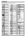
2.03 Symbol Chart
Note that only some of these symbols will appear on your model.
On
Single Phase
Wire Feed Function
Off
Three Phase
Wire Feed Towards
Workpiece With
Output Voltage Off.
Dangerous Voltage
Three Phase Static
Frequency ConverterTransformer-Rectifier
Welding Gun
Increase/Decrease
Remote
Purging Of Gas
Duty Cycle
Continuous Weld
Mode
Percentage
Spot Weld Mode
Circuit Breaker
AC Auxiliary Power
2-2
Spot Time
Fuse
Panel/Local
Amperage
Shielded Metal
Arc Welding (SMAW)
Voltage
Gas Metal Arc
Welding (GMAW)
Hertz (cycles/sec)
Gas Tungsten Arc
Welding (GTAW)
Frequency
Air Carbon Arc
Cutting (CAC-A)
Negative
Constant Current
Positive
Constant Voltage
Or Constant Potential
Direct Current (DC)
High Temperature
Protective Earth
(Ground)
Fault Indication
Line
Arc Force
IPM
Inches Per Minute
Line Connection
Touch Start (GTAW)
MPM
Meters Per Minute
Auxiliary Power
Variable Inductance
Receptacle RatingAuxiliary Power
V
Voltage Input
t
Preflow Time
t1
t2
Postflow Time
2 Step Trigger
Operation
Press to initiate wirefeed and
welding, release to stop.
4 Step Trigger
Operation
Press and hold for preflow, release
to start arc. Press to stop arc, and
hold for preflow.
t
Burnback Time
Disturbance In
Ground System
Art # A-04130
115V 15A
X
%
May 30, 2006
ULTRAFEED A 2000
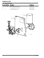
2.04 General Information
The ULTRAFEED A 2000 is a semiautomatic, Variac
controlled wire feeder capable of a 100% duty cycle. The
system offers both load and line voltage compensation
helping to maintain a constant wire feed speed, even with
changes in the input voltage and/or load. The wire feeder
comes complete with a wire spool support assembly.
The ULTRAFEED A 2000’s sheet metal box totally encloses
the solid state control circuitry. A hinged, latched
feedhead cover allows quick and easy access to the
feedhead, featuring tool-less quick change feed rolls.
The ULTRAFEED A 2000 comes with an abundance of
standard features including:
• an on/off rocker switch
• a circuit breaker for total system protection
• a wire feed speed control
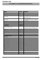
UltraFeed A 2000 Specifications
Input Voltage:
115 VAC
Input Frequency:
50/60 Hz
Input Voltage Tolerance
±10%
Maximum Input Current
1.5 Amps
30 - 650 ipm
Wire Speed Range
.76 - 16.6 m/min
for All Filler Wire Sizes
Wire Sizes
0.024 - 5/64" / 0.6 - 2.0 mm
Maximum Wire
Coil/Spool Weight
Feed Rolls
Welding Current (I)
Welding Gun/Torch Size
(Tweco #4 Std)
60 lb. / 27 kg
Maximum Shielding Gas
Inlet Pressure
Weight (Less Wire)
• an inch switch
Dimensions HxWxD
• a gas purge switch
Approvals
• electromechanical brake for precise wire stopping
• two quick change, gear-driven feed rolls
The ULTRAFEED A 2000 has been designed to comply
with CSA NRTL/C, NEMA EW 3, and IEC 60974-1
standards.
2 (Gear Driven)
450 A @ 100% Duty Cycle
5-8" (15.9mm) nominal
100 P.S.I. / 6.9 Bar
30 lbs. / 13.5 kg
10.3 x 12.4 x 19 in.
262 x 315 x 483 mm
NEMA EW 3
IEC 60974-1 (CE)
Table 2-1: Product Specifications
A 2000
Art # A-07319
Figure 2-1: ULTRFEED A 2000 Front View
May 30, 2006
2-3
ULTRAFEED A 2000
2.05 Features and Benefits
2.06 Options and Accessories
Ready to weld
Supplied with 6ft (2m) control cable with 19-pin male
amphenol plug and .030, .035, .045 in (0.8, 0.9,
1.2mm) drive rolls for hard wire.
Refer to the Appendix 2 section in the back of this
manual for the list of available options and accessories
for this product.
Inch & purge switches
Cold wire inch and gas purge.
Precision wire alignment
Machined feed head and tension arms ensure wire
alignment tolerances ± .002”.
Geared top & bottom drive rolls
Optimized wire traction for improved feedability.
Quick change drive rolls
No tools required.
Speed control fitted
Variac speed control ensured lower operating and repair
cost with improved reliability.
Electromechanical brake
Electromechanical control of the motor brake offers precise stopping of the wire.
Circuit breaker fitted
Built-in input circuit breaker provides total system
protection.
Welding gun quick disconnect
Quick and easy connection and disconnection of the
welding gun.
2-4
May 30, 2006
ULTRAFEED A 2000
SECTION 3:
INSTALLATION
3.01 Connections
3.03 EMI Considerations
Refer to the System Outline drawing in the Appendix of
this manual for details.
Electromagnetic interference (EMI) is common in today’s
complex industrial environment. At times, EMI levels can
become great enough to affect the operation of the
machinery. To help reduce and safeguard against EMI
levels in the welding area, follow these simple guidelines:
1. Make the proper welding cable connections
between the power source and wire feeder and
between the power source and work connection.
2. Connect the control cable from the feeder to the
power source. Control cable extensions are
available. Refer to the Appendix 2 section in the
back of this manual for the list of available options
and accessories for this product.
NOTE
An optional 870000-001 adapter cable will be
required for connection to a power source with
only a 5 pin amphenol connection and AC
voltage outlets. An optional 870093B-001
adapter cable will be required for connection
to a power source with only a 14 pin amphenol
connection. These options are only applicable
to 19 pin plug units.
3. Make the proper gas line connection from the gas
supply to the wire feeder gas valve (if gas will be
used).
4. Attach the welding gun to the wire feeder.
1. Firmly secure all sheet metal panels on the power
source and wire feeder. Repair or replace heavily
corroded or damaged panels and/or fasteners.
2. Keep the welding cables and control cables as
short as possible.
3. Route the ‘+’ and ‘-’ welding cables from a
particular power source together.
4. Keep the welding cables as straight as possible;
avoid coiling up the cables.
5. Route the control cable away from the welding
cables.
NOTE
Grounding of the workpiece may reduce
emissions in some, but not all circumstances.
To prevent the risk of injury or damage to other
electrical equipment when grounding the
workpiece, take care to follow all local laws
and regulations.
5. Connect the welding gun control leads to the wire
feeder gun switch terminals located on the front
of the feeder.
3.02 Grounding
To assure operator safety in the case of a fault condition,
the frame of the power source (welding machine) must
be grounded. The wire feeder sheet metal frame is
grounded only through pin G (for 19 pin plug) of the
control cable that connects to the power source.
Therefore, if the power source frame is not grounded,
then, the wire feeder sheet metal frame is not grounded,
and a shock hazard could possibly develop. Follow the
instructions found in the power source Owner’s Manual
for correct grounding methods.
May 30, 2006
3-1
ULTRAFEED A 2000
3.04 Installation Of Welding Wire Spool
3.05 Adjustment Of Spool Tension
Refer to Figure 3-1.
Adjust the wire spool tension so that the wire will feed
freely into the input wire guide. However, the spool of
welding wire must not “coast” when wire feeding stops.
To adjust the wire spool tension, tighten or loosen the
hub tension bolt accordingly (Refer to Figure 3-1).
NOTE
The wire spool hub supplied with the unit is
provided for mounting a 12 inch diameter
spool of wire. Optional adapters are available
allowing an 8 in diameter spool of wire or a 14
pound coil of wire to be used.
1. Remove the wire spool hub nut by turning
counterclockwise.
2. Orient and slide the spool of wire over the wire
spool hub so that the wire will feed off the bottom
of the spool as the spool rotates counter
clockwise. Make sure that the alignment pin on
the hub enters the hole in the backside of the wire
spool.
3. Replace the wire spool hub nut and turn clockwise
to a snug position.
NOTE
NOTE
Excessive tightening of the hub tension bolt
will result in a shorter motor life.
Wire Spool Hub Nut
Hub Tension Bolt
Alignment Pin
1
The wire must feed from the bottom of the
spool. If it comes off, the top the spool will
have to be removed and turned around.
Additional Wire Spool Support
Shaft Holes (with plugs)
2
Art # A-07264
3
Figure 3-1: Installing Welding Wire Spool
3-2
May 30, 2006
ULTRAFEED A 2000
3.06 Input And Output Wire Guide Installation
Refer to Figure 3-2.
Install the input wire guide (the longer one) by loosening
the input guide lockscrew and inserting the guide into
the hole in the feedhead assembly. The recessed end of
the guide should be towards the wire spool. Adjust the
guide so that it is clear of the feed rolls and tighten the
input guide lockscrew.
Input Guide Lockscrew
Output Guide Lockscrew
Install the output wire guide in the same manner, with
the conical end toward the feed rolls. The tip of the conical
end should be as close to the feed rolls as practical.
Tighten the output guide lockscrew.
NOTE
Before tightening the input and output guide
lockscrews, install the drive roll to help in the
alignment of the wire guides.
Input Wire Guide
Output Wire Guide
Art # A-07265
Figure 3-2: Wire Guide Installation
May 30, 2006
3-3
ULTRAFEED A 2000
3.07 Selection And Installation Of Feed
Rolls
Rotate retainer cap
to align splines
NOTE
Refer to feed roll kit drawing (supplied in the
Appendix A-1) to order feed roll kits. Kit
includes 2 drive rolls, an input wire guide and
an output wire guide for a specific wire type
and size.
1
Style 1: Feed rolls consist of flat smooth top rolls and
double smooth, vee grooved bottom rolls. They feed .024
- .068" hard and tubular wire.
Drive Gear
Style 2: Feed rolls consist of top and bottom flat knurled
top rolls and a double smooth, vee grooved bottom rolls.
They feed .030 - .045" hard and tubular wire.
Style 3: Feed rolls consist of top and bottom double
smooth, vee grooved drive rolls. This style supports 0.035
to 1/16” soft wire.
Retainer Cap
2
Style 4: Feed rolls consist of top and bottom double
knurled, vee grooved grooved drive rolls. They feed .045
- 5/64" hard and tubular wire.
Style 5: Feed rolls consist of top and bottom double cog
top and bottom rolls. They feed .045 - 5/64" tubular wire.
Style 6: Feed rolls consist of top and bottom double Ugrooved top and bottom feed rolls. They feed .035 - 1/16"
soft wire.
Feedroll
NOTE
All grooved feed rolls have their wire size or
range stamped on the side of the roll. On rolls
with different size grooves, the outer (visible
when installed) stamped wire size indicates
the groove in use.
REMOVING OR INST
ALLING FEED ROLLS
INSTALLING
Line up 3 grooves
with 3 splines
Art # A-07579
3
Refer to Figure 3-3
1. Twisting the feed roll retainer cap and align the retaining knob splines with the drive gear splines.
2. Place the new feedroll onto the drive gear splines and
push it abainst the edge of the gear
3. Twist the feedroll retainer cap about 1/4 turn so that
the splines rest against the face of the feedroll.
NOTE
The retainer caps can often be very tight and
may require pliers to turn.
Twist retainer cap
to lock feed roll
in place
Figure 3-3: Feed Roll Installation
3-4
May 30, 2006
ULTRAFEED A 2000
3.08 Welding Gun Compatibility And
Installation
Refer to Figure 3-4.
The ULTRAFEED A 2000 wire feeder is designed to be
used with most welding guns. In some cases, a special
adapter may be required.
To install the welding gun, simply loosen the gun clamp
knob and insert the welding gun into the feedhead until it
stops. Tighten the gun clamp knob and connect the
welding gun control wires to the gun switch receptacle.
NOTE
Before inserting the welding gun into the
feedhead, make sure the gun clamp knob does
not extend into the feedhead; otherwise, the
welding gun cannot be properly inserted.
NOTE
Check for gas leaks. If leaking gas, gun is not
all the way into the feedhead.
Art # A-07266
Feed Head
Gun Adapter
Gun Clamp Knob
Gun Switch Receptacle
Figure 3-4: Welding Gun Installation
May 30, 2006
3-5
ULTRAFEED A 2000
3.09 Threading Wire Into Feedhead
Refer to Figure 3-5.
WARNING
ELECTRIC SHOCK CAN KILL! Make certain the
power source and wire feeder are turned OFF.
Do not turn the power ON until told to do so in
these instructions.
CAUTION
Use care when handling the spooled wire as
the wire tends to “unravel” when loosened
from the spool. Grasp the end of the wire
firmly, and don’t let it get away from you. Make
sure that the end of the wire is straight and
free of burrs.
3. Lift the pressure arm up and pass the wire through the
output wire guide and into the welding gun assembly
(refer to welding gun manual).
4. Close the pressure arm, and lock in position with the
tension lever. To adjust the amount of force the roll
exerts on the welding wire, turn the spring tension
knob clockwise for increased force or
counterclockwise for decreased force.
NOTE
If the force applied to the wire is too great, the
welding wire will “bird nest” in the feedhead
and not feed properly.
5. Turn the welding machine and wire feeder ON, and
set the wire feed speed control to midrange (Refer to
Figure 4-1). Remove contact tube from welding gun.
Refer to the Gun Manual. Press the gun switch or INCH
switch until wire feeds out past the gas diffuser. Thread
the contact tube over the wire and lock into place and
tighten. Cut wire off at about 1/4 inch (6 mm) from
the nozzle.
1. Place end of the welding wire into the input wire guide.
Feed it through the guide and over the drive roll groove
closest to the feedhead casting.
2. Loosen the spring tension knob and pull the tension
lever toward you to unlock the pressure arm.
Spring Tension Knob
WARNING
The wire is electrically “HOT” if wire is fed by
depressing the gun switch. Wire contact with the
workpiece will cause an arc with the gun switch
depressed. Feed motor will run feeding “HOT” wire.
Pressure Arm
Tension Lever
Welding Wire
Art # A-07273
Input Wire Guide
Output Wire Guide
Figure 3-5: Threading Wire Into Feedhead
3-6
May 30, 2006
ULTRAFEED A 2000
SECTION 4:
OPERATION
4.01 Prewelding Procedure
Follow all installation instructions for the wire feeder, the
welding power source, and the welding gun before
attempting to operate the ULTRAFEED A 2000.
1. Make sure all necessary connections have been
made (Refer to “Connections” in the Installation
chapter of this manual).
2. Turn ON the power source and the wire feeder.
3. Push the PURGE switch of the feeder and adjust
the flow of shielding gas.
4. Push the INCH switch of the feeder and adjust
the wire feed speed to the desired value by means
of the wire feed speed control.
!
WARNING
If the gun switch is depressed, the electrode
(welding wire) is electrically “hot”. Do not
permit it to touch any metal or a welding arc
may be established which may be injurious to
someone’s eyes (flash) or skin (burn).
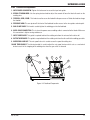
4.02 Front Panel
1. GUN SWITCH RECEPTACLE: The gun switch receptacle accepts the welding gun control wires. The gun
switch receptacle is where a gun switch closure is
inputted to the wire feeder.
2. INCH/PURGE SWITCH: Depressing the INCH switch
(which is in the up position) will feed wire at a speed
set by the WFS control. The wire will not be elecrically
hot when using the INCH switch. Depressing the
PURGE switch (which is in the down position) will
allow shielding gas to flow out of the welding gun
without feeding wire.
3. POWER ON/OFF SWITCH: This switch only the wire
feeder and not the power source (welding machine).
It is used as an on/off switch and also serves as a
circuit breaker.
NOTE:
If the circuit breaker trips, it turns the power
switch to the OFF position. A short cooling
period must be allowed before an attempt is
made to reset the unit by placing the switch in
the ON position.
4. Wire Feed Speed CONTROL: This knob controls wire
feed speed. The wire feed speed can be adjusted during setup or actual welding.
5. Adjust the voltage of the power source to the
desired value. The gun switch must be triggered
to close power source contactor.
3
WARNING
In semiautomatic or automatic wire welding,
the welding wire, wire reel (if used), input
guide, feed rolls, output guide, feedhead, and
welding gun metal parts are all ELECTRICALLY
“HOT”.
4
2
1
A 2000
Art # A-07320
Figure 4-1: Front Panel Controls and Connections
May 30, 2006
4-1
ULTRAFEED A 2000
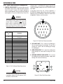
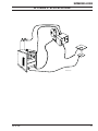
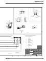
4.03 Rear Panel Controls &Connections
1. CONTROL CABLE SOCKET: The control cable connects
to the power source at this 19-pin connector (of which
5 pins are used). It contains the signals required to
allow the welding power source and the wire feeder to
work together as a system. (Refer to Fig 4-2 and 4-3).
If the power source only has a 5 pin amphenol and AC
voltage outlets, an 870000-001 adapter cable will be
required for proper hookup with the ULTRAFEED A 2000
wire feeder.
If the power source only has a 14 pin amphenol, a
870093B-001 adapter cable will be required for proper
hookup with the ULTRAFEED A 2000 wire feeder. Refer
to Appendix 2 Options and Accessories.
WARNING
Keyway
The protective earth ground (pin G) of the
control cable is established only when the
power source is properly grounded. See the
power source owner’s manual for proper
grounding methods. Also refer to page 3-1.
A
B
C
Control Cable
Pin
A
B
C
D
E
F
G
H
J
K
L
M
N
P
R
S
T
U
V
Contactor Hot Relay Closure To
Energize
Contactor Neutral Power Source
Not Used
Not Used
120 VAC Hot
120 VAC Neutral
Protective Earth Ground
Not Used
Not Used
Not Used
Not Used
Not Used
Not Used
Not Used
Not Used
Not Used
Not Used
Not Used
Not Used
Table 4-1: 19-Pin Control Cable Connections
N
P
D
Function
M
U
V
R
E
L
K
T
S
F
J
H
G
Figure 4-2: Rear Panel 19 pin connections
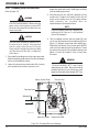
2. GAS VALVE INLET: This is where the shielding gas
hose is connected to the wire feeder. The gas valve
controls the “on/off” flow of shielding gas through
the welding gun.
3. WIRE FEED ACCESS: This is where the welding wire
feeds through the sheet metal housing to the wire
feeder.
4. WELDING CURRENT LEAD ACCESS: This is where
the welding current lead from the power supply feeds
through the sheet metal housing.
2
3
1
CAUTION
The relay contacts between pins A and B have
a maximum rating of 1/3 Horsepower (HP),
115 VAC or 10A, 230 VAC.
4-2
4
Art # A-07322
Figure 4-3: Rear Panel Connections
May 30, 2006
ULTRAFEED A 2000
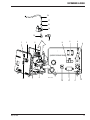
4.04 Feedhead Components
1. INPUT GUIDE LOCKSCREW: Tighten this lockscrew to secure the input wire guide.
2. SPRING TENSION KNOB: Use the spring tension knob to adjust the amount of force the feed rolls exert on the
welding wire.
3. FEEDROLL GEAR / KNOB : This knob is used to secure the feedroll to the pressure arm. Rotate the knob to change
the feedroll.
4. PRESSURE ARM: This arm pivots off the front of the feedhead to allow access to the wire guides and wire path.
5. GUN CLAMP KNOB: This knob is used to tighten the welding gun into the feedhead.
6. WELD CABLE CONNECTION: This is where the power source welding cable is connected to the feeder. Make sure
this connection is tight or arcing could occur.
7. INPUT WIRE GUIDE: This guide is required to direct the welding wire from the wire reel to the drive roll.
8. OUTPUT WIRE GUIDE: This guide is required to direct the welding wire from the drive roll to the welding gun cable.
9. WIRE SPOOL HUB NUT: The wire spool hub nut is used to secure the spool of welding wire.
10.HUB TENSION BOLT: The hub tension bolt is used to adjust the wire spool tension which acts as a mechanical
brake to assist in the stopping of the welding wire when the gun switch is released.
10
1
2
3
4
8
9
5
7
6
Art # A-07326
Figure 4-4: Feedhead Components
May 30, 2006
4-3
ULTRAFEED A 2000
4.05 Power Source Compatibility
The Ultrafeed A 2000 wire feeder will work with any Thermal Arc CV or CC/CV power source. If the Thermal Arc
power source only offers a 5 pin amphenol connector
and AC voltage outlets, a 870000-001 adapter cable will
be required to connect between the 19 pin control cable
of the wire feeder and the 5 pin amphenol connector and
AC voltage outlets of the power source.
If the Thermal Arc power source only offers a 14 pin
amphenol connector, a 870093B-001 adapter cable will
be required to connect between the 19 pin control cable
of the wire feeder and the 14 pin amphenol connector of
the power source.
The Ultrafeed A 2000 will also work with most competitive power sources that provide 115 VAC and require a
relay closure to become energized.
4.06 Power Source Compatability Details
Power Source Compatibility Details
Machine
Details
PowerMaster 500
Fully Compatible
PowerMaster 500P
Fully Compatible
ExcelArc 6045
Fully Compatible
ExcelArc 8065
Fully Compatible
Fabstar 4030
Fully Compatible
Arc Master 300 MST
Fully Compatible
Arc Master 400 MST
Fully Compatible
Arc Master 400 MSTP
Fully Compatible
Figure 4-5: Power Source Compatability
4-4
May 30, 2006
ULTRAFEED A 2000
SECTION 5:
MAINTENANCE
5.01 Cleaning The Unit
5.04 System Maintenance
Periodically, clean the inside of the wire feeder and feedhead
assembly by using a vacuum cleaner or clean, dry,
compressed air of not more than 25 psi/172 kPa/1.72 bar
pressure. After cleaning the unit, check all electrical
components for loose or faulty connections and correct if
necessary.
Scope
5.02 Cleaning The Feed Rolls
Clean the grooves on the lower drive roll frequently. This
cleaning operation can be done by using a small wire
brush. Also, wipe off or clean the grooves on the upper
roll. After cleaning the feed rolls, tighten the feed roll
retaining knobs accordingly.
5.03 Feedhead Maintenance
The troubleshooting guide is intended to be used by
qualified service technicians. The troubleshooting guide
contains information which can be used to diagnose and
correct unsatisfactory operation or failure of the various
components of the wire feeder. Each symptom of trouble
is followed by a list of probable causes and the procedure
necessary to correct the problem.
Safety
To ensure safe operation and service, read this entire
manual before attempting to service or repair this
machine. The service technician may be asked to check
voltage levels while the machine is turned ON. To assure
safety, use care and follow all instructions accordingly.
The only point of maintenance in the feedhead assembly
is the motor brushes. Inspect these about every 300 hours
of operation. When these brushes are worn to about 1/8"
(3.2 mm), new brushes should be installed.
CAUTION
Neglect in brush maintenance may cause
damage to the drive motor commutator
resulting in a shorter motor operating life.
Cap
407190-1
Brush
407191-2
Art # A-04195
Feed Motor
Brush Holders
Figure 5-1: Brush Maintenance
May 30, 2006
5-1
ULTRAFEED A 2000
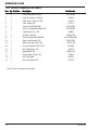
5.05 Gas Valve Maintenance
Foreign material inside the valve body is the major cause
of gas valve failure or improper operation. Foreign material
usually enters the valve body when disconnected gas lines
are allowed to come in contact with the floor or ground
before being connected or reconnected to the gas valve.
In general, sluggish operation and/or gas leakage are signs
the gas valve needs to be cleaned internally. To clean the
gas valve internally, follow these steps:
NOTE
Before disassembly of the gas valve, take note
of the orientation of inlet (marked IN) and outlet
ports with respect to electrical connections. The
reassembled gas valve should have the same
orientation.
After maintenance, operate the gas valve a few times to
be sure of proper operation. If the gas valve continues to
show signs of improper operation, replace the gas valve
assembly.
Art # A-04202
Coil
Yoke
Body Gasket
Plugnut / Core Tube
Sub-Assembly
Bracket
1. Remove input power from the wire feeder, and
depressurize the gas valve.
Core Assembly
Core Spring
2. Remove the gas valve from the wire feeder.
Valve Body
3. Remove the (2) bracket screws and bracket from the
yoke of the gas valve.
4. Slip the yoke (containing coil) off the plugnut/core
tube subassembly.
5. Remove the plugnut/core tube subassembly with the
body gasket attached.
Bracket Screws (2)
Figure 5-2: Gas Valve Assembly
6. Remove the core assembly and core spring.
7. All parts should now be inspected for foreign material
and cleaned with a lint-free cloth. Do not nick or
scratch any internal parts of the gas valve.
8. Reassemble the gas valve in reverse order of
disassembly paying careful attention to Figure 5-2.
NOTE
Tighten (2) bracket screws evenly to insure
proper body gasket compression. Torque
bracket screws to 20 inch-pounds (2.3 Newton
Meters).
9. Assemble the gas valve to the wire feeder.
NOTE
It may be necessary to apply pipe compound
sparingly to the gas adapter male threads only.
Do not apply compound to female threads of
gas valve or first two threads of male fittings.
Also, make sure the inlet port (marked IN) side
of the gas valve is connected to the main gas
supply; otherwise, the gas valve will leak.
5-2
May 30, 2006
ULTRAFEED A 2000
SECTION 6:
TROUBLESHOOTING
6.01 Troubleshooting Hints
Examine connections for proper assembly and contact
before replacing an electrical component or printed circuit
board. Wire lugs should be in tight contact with the lead’s
conductor and should be crimped to the lead’s insulation.
The mating surfaces of the connection should be clean
and free of oxidation.
6.02 Troubleshooting Guide
NOTE
Refer to the Connection Diagram and the
Schematic Diagram in the Appendix chapter
of this manual for graphical assistance in
disassembling and troubleshooting the wire
feeder.
Faulty connections or wiring problems are often the cause
of an equipment malfunction!
Do not pull on wires to disassemble connections. Firmly
grasp each lug or connector when disconnecting. Pulling
on wires for disassembly can damage the integrity of the
connection and cause future malfunctions.
Prior to disassembly or servicing of the machine, note
the wiring and connections in the machine. Reassembling
should place the wires in the same location and routing
as received from the factory. Keep wires and leads away
from hot parts and sharp objects.
All signals referenced in the following troubleshooting
guide can be measured with a digital multimeter (DMM).
WARNING
ELECTRIC SHOCK can kill.
Follow all safety precautions.
Do not touch live electrical parts.
Turn OFF input power before servicing the
machine unless otherwise noted.
Only qualified technicians are to service the
machine.
WARNINGS
PC boards and their components are static
sensitive devices.
Use static proof bags.
Use grounded wrist strap.
Only qualified personnel should test or handle
these devices.
NOTE
Refer to the Appendix 3 Connection and
Schematic Diagrams in the Appendix Section
of this manual for graphical assistance in
disassembling and troubleshooting the wire
feeder.
The acceptable tolerance (in most cases) on
resistance and voltage measurements made
with the DMM is ±10%.
Use only genuine replacement parts.
May 30, 2006
6-1
ULTRAFEED A 2000
A. Unit is completely inoperative - nothing functions
1. Make sure all connections have been made to both
the power source and wire feeder.
a. See Connections section of this manual.
2. Make sure both the power source and wire feeder
are turned ON.
3. Make sure ground fault protection circuit has not
activated.
a. If the ground fault protection has activated,
input power will have to be reset before normal
operation can resume.
4. Check for a damaged control cable (P1) that
connects between the power source and wire
feeder.
B. Wire feed motor operates but wire does not feed
or feeds erratically
1 Check for incorrect voltage and/or wire feed speed
settings.
2. Make sure all connections to the wire feeder are
tight.
3. Make sure feed rolls are of the correct size and
properly installed.
4. Check for too little or too much pressure on the
welding wire.
a. See spring tension knob in the Interior
Components section of this manual.
5. Check to see if wire spool tension is too great.
5. Check for a tripped circuit breaker (S2).
a. If the circuit breaker trips, it turns the power
switch (S2) to the OFF position. A short cooling
period must be allowed before an attempt is
madeto reset the unit by placing switch S2 in
the ON position.
6. Check for a damaged power on/off switch (S2).
7. Check on/off switch (S2), terminal block (TB1),
variable transformer (T1), and stepdown
transformer (T2) for loose or faulty connections.
a. With input power supplied to the wire feeder
and the on/off switch ON, measure the AC voltage from TB1-1 to TB1-2. The measured
voltage should be 120 VAC.
b. If not, check for an .activated. protection device
in the power source.
a. See Adjustment Of Spool Tension section of
this manual.
6. Check for restriction in welding gun and/or contact
tip.
7. Check for the correct size welding gun liner and
contact tip for welding wire being used.
8. Check for failed insulator on drive gear assembly
- motor shaft turning inside insulator
a. Replace drive gear assembly.
C. Wire wraps around the feed rolls
1. Check for too much pressure on the welding wire.
a. See spring tension knob in the Interior
Components section of this manual.
2. Check for proper alignment of the input and output
wire guides.
3. Check for the correct size welding gun liner and
contact tip for welding wire being used.
6-2
May 30, 2006
ULTRAFEED A 2000
D. Wire does not feed with gun switch depressed
1. Check to see if the feed rolls are mechanically
restricted.
2. Move the WFS control knob (on the front panel)
off the minimum setting.
E. Wire feed motor continues to run after gun switch
has been released
1. Check the continuity of the welding gun trigger
leads with the trigger released.
a. If shorted, repair or replace the welding gun.
3. Check the continuity of the welding gun trigger
leads with the trigger depressed.
2. Check for a shorted gun switch receptacle (J1),
terminal block (TB1), or inch/purge switch (S1).
a. If no continuity, repair or replace the welding
gun.
3. Check to see if relay (K1) is functioning properly.
4. Check all components for loose or faulty
connections.
5. With the wires removed from resistor (R1),
measure the resistance. The measured resistance
should be in the range of 4.6 to 6.6 ohms.
a. If not, replace resistor (R1).
6. With input power supplied to the wire feeder and
the on/off switch ON, check the following items:
a. Measure the AC voltage across the secondary
of the stepdown transformer (T2). The
measured voltage should be 24 VAC.
If not, replace the stepdown transformer (T2).
b. Depress the welding gun trigger; relay (K1)
should operate.
If not, replace relay (K1).
c. With the WFS control set to maximum,
measure the AC voltage from the wiper of the
variable transformer (T1) to TB1-2. The
measured voltage should be 120 VAC.
If not, replace the variable transformer (T1).
7. Check wear on motor brushes.
a. See Feedhead Maintenance in the Maintenance
chapter of this manual.
8. Replace bridge rectifier (CR1) if necessary.
F. No wire feed speed (WFS) control
1. Check for a loose WFS control knob.
2. Check variable transformer (T1), bridge rectifier
(CR1), and terminal block (TB1) for loose or faulty
connections.
3. With input power supplied to the wire feeder and
the on/off switch ON, measure the AC volt-age from
the wiper of the variable transformer (T1) to TB12. The measured voltage should change from 0 to
120 VAC while adjusting the WFS control knob
from minimum to maximum.
a. If not, replace the variable transformer (T1).
G. Wire feeds but no gas flows
1. Check to see if the gas cylinder is empty or the
valve closed.
2. Make sure the proper gas flow rate has been set.
3. Check for a possible restriction in the gas line or
gas valve.
4. Check to see if the welding gun nozzle is plugged.
5. Check gas valve (L1), terminal block (TB1), and
inch/purge switch (S1) for loose or faulty
connections.
6. With input power supplied to the wire feeder and
the on/off switch ON, measure the AC volt-age
across the gas valve terminals with the welding
gun trigger depressed. The measured voltage
should be 24 VAC.
a. If 24 VAC is present on the gas valve terminals
and gas does not flow, replace the gas valve
(L1).
May 30, 2006
6-3
ULTRAFEED A 2000
H. Gas Flows all the time or leaks
1. Make sure all connections are tight.
2. Check for foreign material inside the gas valve.
a. See Gas Valve Maintenance in the Maintenance
chapter of this manual.
I. Wire feeds but there is no arc
1. Make sure all connections have been made to both
the power source and wire feeder.
a. See Connections section of this manual.
2. Check for a damaged control cable (P1) that
connects between the power source and wire
feeder.
3. Check relay (K1), inch/purge switch (S1), and
terminal block (TB1) for loose or faulty
connections.
4. With input power supplied to the wire feeder and
the on/off switch ON, depress the welding gun
trigger. Make sure .all. relay (K1) contacts are
properly operating.
a. If not, replace relay (K1).
J. Wire does not feed with inch switch depressed or
gas does not flow with purge switch depressed
1. Check inch/purge switch (S1) and terminal block
(TB1) for loose or faulty connections.
2. Check for a defective inch/purge switch (S1).
6-4
May 30, 2006
ULTRAFEED A 2000
SECTION 7:
PARTS LIST
7.01 Equipment Identification
All identification numbers as described in the Introduction
chapter must be furnished when ordering parts or making
inquiries. This information is usually found on the
nameplate attached to the equipment. Be sure to include
any dash numbers following the Part or Assembly
numbers.
7.02 How To Use This Parts List
The Parts List is a combination of an illustration and a
corresponding list of parts which contains a breakdown
of the equipment into assemblies, subassemblies, and
detail parts. All parts of the equipment are listed except
for commercially available hardware, bulk items such as
wire, cable, sleeving, tubing, etc., and permanently
attached items which are soldered, riveted, or welded to
other parts. The part descriptions may be indented to show
part relationships.
To determine the part number, description, quantity, or
application of an item, simply locate the item in question
from the illustration and refer to that item number in the
corresponding Parts List.
PART NUMBER:
W3200001
May 30, 2006
7-1
ULTRAFEED A 2000
7.03 External Components and Labels
Item Qty
Qty.. Ref
Ref.. Des.
Description
Part Number
1
8
Plug, Black Nylon Snap, WF
870716PKD
3
1
Label, Precaution, Arc Equip
204036
4
1
Label, Electric Shock US, WF
407099
5
1
Label, Feeder, WF
170101
6
1
Cover,Assy,VA2000/A2000
871242PKD
7
4
Spacer, Threaded M6 Rubber, WF
870729PKD
8
1
Label,Moving Parts, WF
9
2
Bushing, Snap, WF
10
1
Base Assembly,VA2000/A2000
12
1
Spool, Hub Assembly, WF
870987PKD
13
1
Spool, Hub Locking Nut, WF
170201-002
14
1
Screw,Hex HD,3/8"-16x1",STZP
See Note
15
1
Hub, Spool Spacer, WF
405449
16
1
Spring,Spool Hub
17
1
Spacer, Spool Tension, WF
375683
18
1
Hub, Wire Spool
405376
19
1
Shaft, Wire Spool, WF
375176
406636
405362-002
870731WBLKPKD
400562-027
Note:This part may be purchased locally.
7-2
May 30, 2006
ULTRAFEED A 2000
1
5
6
3
4
10
7
9
13
14 15 16 17
18
19
8
12
Art # A-07582
May 30, 2006
7-3
ULTRAFEED A 2000
7.04 Electrical Components
Item Qty
Qty.. Ref
Ref.. Des.
Description
1
1
S1
Switch, Rocker, 1.5 Amps, WF
870032-001
2
1
S2
Switch, 4PDT,(Inch, Purge), WF
407135-001
3
1
Knob,Control,1/4" IDx1.6"
870696PKD
4
1
PCB, Ground Circuit, WF
375581
5
1
7
1
Transformer, Powerstat, WF
400244
8
1
Resistor,5.6 Ohm,30W, WF
405626-003
9
1
Suppressor, W/Lug AY., WF
202258-001
10
1
Rectifier, Bridge, 35A, 800V
409554-002
11
1
Relay, Enclosed, WF
403056-011
12
1
Wire Harness, A2000, WF
870980PKD
13
1
Adaptor, Gas RH 1/8NPT-5/8, WF
14
1
15
T1
16DA3134
7978024PKD
Valve, Solenoid, 24VAC, WF
404162-008
1
Fitting, Elbow street 90, WF
7978025PKD
16
1
Fitting, Barbed, Polypro, WF
203846-002
17
2
Wire Tie, Nylon, 4"
18
1
Tube, Water or Gas, WF
7-4
L1
Transformer,Control,120V-24V
Part Number
See Note
16DA3304-017
May 30, 2006
ULTRAFEED A 2000
18
17
16
14
15
13
1
8
5
3
5
9
6
(INSIDE OF REAR PANEL)
2
May 30, 2006
7
4
Art # A-07509
10
11
4
12
7-5
ULTRAFEED A 2000
7.05 Feedhead Components
Item Qty
Qty.. Ref
Ref.. Des.
Description
Part Number
1
1
Knob,Control,1/4" IDx3/4"
870082
2
1
Rod,Tension Arm,2R & 4R Plate
870425
3
1
Washer, 1/4" Flat, WF
See Note
4
1
Spring,Pressure Adj,2R Plate
400562-033
5
1
Pin, Roll, 3/32" ODx1/2"
7962029PKD
6
1
Guide,Input,.030-.045,2R Plate
377941
7
2
Screw,PHCR,#8-32x1/2",STZP
See Note
8
1
Screw,Hex HD,3/8"-16x3/4,STZP
See Note
9
1
Washer, 3/8",Lock, WF
See Note
10
1
Washer, 3/8",Flat, WF
See Note
11
1
Knob, Clamp, 2R Plate
171380
12
1
Clamp, MIG gun,2R Plate
171362
13
1
Spring,Clamp,2R Plate
14
1
Gas Nipple, #10-32 UN,2R Plate
375298
15
1
Guide,Output, 2R Plate
375655
16
1
Pressure Arm, 2R M/C, WF
870679PKD
17
1
Feed Plate, 2 Roll,Tweco#4
870932PKD
18
1
Pin,#6x50mm,2R & 4R Plate
870509
19
3
Screw,PHCR,1/4"-20x3/4",STZP
See Note
20
3
Insulator,Screw mtg,2R Plate
171374
21
2
Retainer, Drive Gear,2R Plate
870733PKD
22
1
Gear, Drive Roll, 2R Plate
870560PKD
400562-048
Note:This part may be purchased locally.
7-6
May 30, 2006
ULTRAFEED A 2000
Art # A-07581
22
21
1
2
3
4
20
16
5
19
18
6
17
7
9
8
10
7
15
13
12
14
11
May 30, 2006
7-7
ULTRAFEED A 2000
7.06 Feed Drive Motor
Item Qty
Qty.. Ref
Ref.. Des.
Description
Part Number
1
1
Motor, Feed Drive, 20 VDC, WF
204994-002
2
1
Insulator,Motor,28.7 ID,2R Plate
870695-002PKD
3
1
Plate, MTG, Feedhead, WF
870122CLAPKD
B1
1
3
Art # A-07503
2
7-8
May 30, 2006
ULTRAFEED A 2000
APPENDIX 1: FEED ROLL KITS
FEED ROLL KITS (#375980-Series) 2 ROLL
Style 1
Style 2
Flat
Double
Smooth "V"
Flat Knurled
Double
Smooth "V"
Hard
Hard
.024" / 0.6mm
375980-031
-
-
.030", .035" / 0.8, 0.9mm
375980-001 375980-003
375980-010
.030", .035", .045" / 0.8, 0.9, 1.2mm
375980-028* 375980-029
-
-
-
-
.035" / 0.9mm
375980-040*
-
-
-
-
375980-032
-
-
375980-030
-
-
-
-
375980-092
375980-022
-
-
-
375980-033
-
Top
Bottom
Wire Type
Style 3
Double Smooth
"V"
Double Smooth
"V"
Style 4
Double
Knurled "V"
Double
Knurled "V"
Style 5
Style 6
Double Cog
Double "U"
Double Cog
Double "U"
Tubular
Soft (Aluminum)
-
-
-
-
-
-
Soft/Hard/Tubular Hard/Tubular
Wire Size
.035", .045" 3/64" / 0.9, 1.2, 1.2mm
.045" / 1.2mm
375980-002* 375980-004
3/64 / 1.2mm
-
-
375980-011
.052" / 1.3mm
375980-090*
-
375980-012
-
-
-
-
-
375980-017
375980-023
-
375980-005*
-
-
-
-
375980-034
.052", 1/16" / 1.3, 1.6mm
1/16" / 1.6mm
.068" / 1.7mm
-
-
-
-
-
-
5/64" / 2.0mm
375980-006*
-
-
375980-018
-
-
Notes: 1) One Kit (# 375980-028) is supplied standard w ith each w ire feeder.
2) Feed Roll Kits include: Drive Rolls; Input & Output Guides
3) Narrow 30° "V"
May 30, 2006
A-1
ULTRAFEED A 2000
APPENDIX 2: OPTIONS AND ACCESSORIES
Product
KITS
Ground Fault Interrupt Kit
ACCESSORIES
Drive Roll Kits
Part No.
870081
375980-028
Control Cable
6 ft (1.8m)
15ft (4.5m)
25ft (7.6m)
50ft (15.2m)
100ft (30.5m)
A-2
One kit (#375980-028) is supplied standard with
each wire feeder, see drive roll kit chart to select a
different drive roll style
Control cable from wire feeder to power source (A
6ft. control cable, #374878-006 is supplied with
the wire feeder)
374878-006
374878-015
374878-025
374878-050
374878-100
Complete interconnect assembly from wire feeder
to power source, includes control cable, welding
power cable and gas hose in a sheathed cover.
Interconnect Cable Assembly
6 ft (1.8m)
15ft (4.5m)
25ft (7.6m)
50ft (15.2m)
Wire Spool Adaptor
10 lb (4.5kg), 8” spool
15 lb (6.8kg), 8” spool
Spool Cover
30 lb (13.6kg) spool
60 lb (27.2kg) spool
Wire Reel Kit
Wire Coil Adaptor
14 lb (6.4kg) coil
60 lb (27.3kg) coil
Wire Feeder Cart
Lift Eye Kit
MIG Gun Holder Kit
MIG Gun Adaptor Kits
Tweco® #5
Miller®
Euro-style
Cable Adapters
19 pin wire feeder to 5 pin power source
19 pin wire feeder to 14 pin power source
Description
W4009200
W4009201
W4009202
W4009203
375585-001
375864-001
375582A-004
375733A-001
870059
375942A
407142A
W4000001
W4002001
171463
Electrically isolated
870395
870397
171449
870000-001
870093B-001
For older style power sources
For Miller® or 14 pin style power sources
May 30, 2006
ULTRAFEED A 2000
APPENDIX 3: SYSTEM OUTLINE
Art # A-07403
May 30, 2006
A-3
ULTRAFEED A 2000
APPENDIX 4: WIRE DIAGRAM
12
11
10
9
1
H
8
7
10
BK (C)
11
11 LINE
1 BL
19 BR
5
16 OR
5
B1
9
2 BK
J1
5
3
12(K)
RD (M)
2
S2
BK (M)
G
4
S1
31 BL
5
7
21 OR
5
20 RD
5
6 BK
17 GY
23 BR
5
F
6 BK
18 RD
5
12 BR
TB1
6
4
12
6
12
5
10
2
2
2
10
24 VT
8
14 RD
7
19 BR
6
18 RD
21 OR
16 OR
5
4
9
T1
6
8
2
23 BR
12 BR
15 RD
RD (M)
2
2
6
3
WT-BL
14
3
1 BL
2
E
11 VT
13 VT
20 RD
4
3
4
3 WT
1
4 9 WT
8 WT (T)
1
4 YL
5
FRONT PANEL
2
3 WT
WT (C)
1
BK (T)
2 BK
9
11
8
1
BOTTOM PANEL
D
TB1-1
S2
BK
TB1-4
E
CW
T1
24V
T2
P1
J1
AC
C
TB1-6
TB1-7
TB1-2
WT
F
R1
6
K1
L1
RV1
G
GN
CR1
K1
K1
B
TB1-8
3
B
9
B1
AC
+
K1
B
12
-
P1
A
A-4
RD
AC
SEE NOTE 1
A
7
OR
11
4
10
9
8
7
May 30, 2006
ULTRAFEED A 2000
6
5
4
3
2
1
4
WH (T)
7 RD
4 YL
9
2
9 WT
-
8
5
BK (M)
T2
3
7
WT-YL
14
K1
RD (C)
11
11
14
2
WT-BL
8
WT-OR
WT-YL
AC
17 GY
4
6
7
9
A
B
7 RD
2
8 BL
7
15 RD
5
4
R1
11 VT
VIEWED FROM TOP OF FEEDER
8 BL
31 BL
5
6
2
F
5
8
AC
BK (C)
WT (C)
+
GN (C)
P1
13
14
5
-
11
OR (C)
13 VT
6 BK
3
G
WT-OR
6
1
H
5
7
+
6 BK
BK (T)
5
CR1
GN (C)
RD (C)
OR (C)
11
1
5
12
14
6
6
24 VT
5
RV1
L1
14 RD
5
GN (C)
E
14
13
GN (C)
GROUND
SCREW
REAR PANEL
D
NOTES:
1. WRAP GREEN GROUND WIRE FROM CONTROL CABLE AROUND THE REED SWITCH
ON THE GROUND FAULT BOARD 4 TIMES, AND THEN SECURE GROUND
WIRE TO GROUND FAULT BOARD WITH WIRE TIE.
CENTER POSITION ON
LEGEND
B1
MOTOR, WIRE FEED
CR1
RECTIFIER, BRIDGE
J1
RECEPTACLE, GUN SWITCH
K1
RELAY, CONTROL, 24 VAC, DPDT
L1
GAS VALVE, 24 VAC
P1
PLUG, CONTROL, 19 PIN AMPHENOL
R1
RESISTOR, 5.6 OHM, 30W
RV1
SUPPRESSOR
S1
SWITCH, INCH/PURGE
S2
ON/OFF SWITCH,
T1
TRANSFORMER, VARIABLE
T2
TRANSFORMER, STEPDOWN
TB1
TERMINAL STRIP
C
CIRCUIT BREAKER, 1.5 A
A
150
TECHPUB
11/98
11/98
B
OUTSIDE DISTR.
DISTRIBUTION TABLE
CHANGE RECORD
E.C. No.
USER
DATE
REV AA
5-31-06
FILE NAME
PLOT DATE
870143
3-22-00
FINISH CODE PER
NONE
ACTIVITY
REPLACED BY
REPLACES
QUANTITY-U.M.
COMM. CLS.
MATERIAL NO.
UNLESS OTHERWISE SPECIFIED
DIMENSIONS ARE IN INCHES/MILLIMETERS
TOLERANCES BELOW APPLY EXCEPT FOR
VENDOR DESIGNED PARTS AND ITEMS.
PRODUCED TO RECOGNIZED STANDARDS.
FRACT.
INCH
DECIMAL-INCH
.0 ± .1
.00 ± .02
.000 ± .003
TITLE
DIAGRAM,CONNECTION&SCHEMATIC
± 3°
METRIC
MODEL17A(CE-VERSION)
0. ± 1.0mm
0.0 ± 0.4mm
0.00 ± 0.1mm
DESIGNED
DO NOT SCALE DRAWING
Art # A-07580
May 30, 2006
ANGLES
DESCRIPTIVE DATA
(M) MOTOR LEAD
(T) TRANSFORMER LEAD
(C) CONTROL CABLE LEAD - P1
6
± TOL
MATERIAL SPEC.
CONFIDENTIAL: This drawing, including all information
contained thereon, is the exclusive and confidential property of
Thermal Arc Corporation of Troy, Ohio 45373 . This drawing is
not to be copied, reproduced, delivered or disclosed to others,
in whole or in part, except with express written permission.
5
4
3
DRAWN
TLT
DBB
CHECKED
APPROVED
TLT
TLT
SIZE
d
A THERMADYNE Company
d
D
DATE
SCALE
11-4-98
FULL
RECORDS
A
ITEM TYPE
11-4-98
DWG. NO.
SHEET
SHEET
870143
TROY, OHIO 45373 , U.S.A.
2
1
A-5
LIMITED WARRANTY
This information applies to Thermal Arc products that were purchased in the USA and Canada.
April 2006
LIMITED WARRANTY: Thermal Arc®, Inc., A Thermadyne Company ("Thermal Arc"),
warrants to customers of authorized distributors ("Purchaser") that its products will be free
of defects in workmanship or material. Should any failure to conform to this warranty
appear within the warranty period stated below, Thermal Arc shall, upon notification
thereof and substantiation that the product has been stored, installed, operated, and
maintained in accordance with Thermal Arc's specifications, instructions,
recommendations and recognized standard industry practice, and not subject to misuse,
repair, neglect, alteration, or damage, correct such defects by suitable repair or
replacement, at Thermal Arc's sole option, of any components or parts of the product
determined by Thermal Arc to be defective.
This warranty is exclusive and in lieu of any warranty of
merchantability, fitness for any particular purpose, or other warranty of
quality, whether express, implied, or statutory.
Limitation of liability: Thermal Arc shall not under any circumstances be liable for special,
indirect, incidental, or consequential damages, including but not limited to lost profits and
business interruption. The remedies of the purchaser set forth herein are exclusive, and
the liability of Thermal Arc with respect to any contract, or anything done in connection
therewith such as the performance or breach thereof, or from the manufacture, sale,
delivery, resale, or use of any goods covered by or furnished by Thermal Arc, whether
arising out of contract, tort, including negligence or strict liability, or under any warranty,
or otherwise, shall not exceed the price of the goods upon which such liability is based.
No employee, agent, or representative of Thermal Arc is authorized to change this
warranty in any way or grant any other warranty, and Thermal Arc shall not be bound by
any such attempt. Correction of non-conformities, in the manner and time provided
herein, constitutes fulfillment of thermal’s obligations to purchaser with respect to the
product.
This warranty is void, and seller bears no liability hereunder, if purchaser used
replacement parts or accessories which, in Thermal Arc's sole judgment, impaired the
safety or performance of any Thermal Arc product. Purchaser’s rights under this warranty
are void if the product is sold to purchaser by unauthorized persons.
The warranty is effective for the time stated below beginning on the date that the
authorized distributor delivers the products to the Purchaser. Notwithstanding the
foregoing, in no event shall the warranty period extend more than the time stated plus
one year from the date Thermal Arc delivered the product to the authorized distributor.
Warranty repairs or replacement claims under this limited warranty must be submitted to
Thermal Arc via an authorized Thermal Arc repair facility within thirty (30) days of
purchaser's discovery of any defect. Thermal Arc shall pay no transportation costs of any
kind under this warranty. Transportation charges to send products to an authorized
warranty repair facility shall be the responsibility of the Purchaser. All returned goods
shall be at the Purchaser's risk and expense. This warranty dated April 1st 2006
supersedes all previous Thermal Arc warranties. Thermal Arc® is a Registered
Trademark of Thermal Arc, Inc.
WARRANTY SCHEDULE
This information applies to Thermal Arc products that were purchased in the USA and Canada.
April 2006
ENGINE DRIVEN WELDERS
WARRANTY PERIOD
Scout, Raider, Explorer
Original Main Power Stators and Inductors .................................................................................. 3 years
LABOR
3 years
Original Main Power Rectifiers, Control P.C. Boards ................................................................... 3 years
3 years
All other original circuits and components including, but not limited to, relays,
1 year
switches, contactors, solenoids, fans, power switch semi-conductors.......................................... 1 year
Engines and associated components are NOT warranted by Thermal Arc, although
most are warranted by the engine manufacturer .............................................................
See the Engine’s Warranty for Details
GMAW/FCAW (MIG) WELDING EQUIPMENT
WARRANTY PERIOD
Fabricator 131, 181; 190, 210, 251, 281; Fabstar 4030;
PowerMaster 350, 350P, 500, 500P; Excelarc 6045.
Wire Feeders; Ultrafeed, Portafeed
Original Main Power Transformer and Inductor............................................................................ 5 years
Original Main Power Rectifiers, Control P.C. Boards, power switch semi-conductors ................. 3 years
All other original circuits and components including, but not limited to, relays,
switches, contactors, solenoids, fans, electric motors................................................................... 1 year
GTAW (TIG) & MULTI-PROCESS INVERTER WELDING EQUIPMENT
WARRANTY PERIOD
160TS, 300TS, 400TS, 185AC/DC, 200AC/DC, 300AC/DC, 400GTSW, 400MST,
300MST, 400MSTP
Original Main Power Magnetics.................................................................................................... 5 years
Original Main Power Rectifiers, Control P.C. Boards, power switch semi-conductors ................. 3 years
All other original circuits and components including, but not limited to, relays,
switches, contactors, solenoids, fans, electric motors................................................................... 1 year
PLASMA WELDING EQUIPMENT
WARRANTY PERIOD
Ultima 150
Original Main Power Magnetics.................................................................................................... 5 years
Original Main Power Rectifiers, Control P.C. Boards, power switch semi-conductors ................. 3 years
Welding Console, Weld Controller, Weld Timer ........................................................................... 3 years
All other original circuits and components including, but not limited to, relays,
switches, contactors, solenoids, fans, electric motors, Coolant Recirculator. ............................... 1 year
SMAW (Stick) WELDING EQUIPMENT
WARRANTY PERIOD
Dragster 85
Original Main Power Magnetics..................................................................................................... 1 year
Original Main Power Rectifiers, Control P.C. Boards .................................................................... 1 year
All other original circuits and components including, but not limited to, relays,
switches, contactors, solenoids, fans, power switch semi-conductors .......................................... 1 year
160S, 300S, 400S
Original Main Power Magnetics.................................................................................................... 5 years
Original Main Power Rectifiers, Control P.C. Boards ................................................................... 3 years
All other original circuits and components including, but not limited to, relays,
switches, contactors, solenoids, fans, power switch semi-conductors .......................................... 1 year
GENERAL ARC EQUIPMENT
WARRANTY PERIOD
Water Recirculators ....................................................................................................................... 1 year
Plasma Welding Torches.............................................................................................................180 days
Gas Regulators (Supplied with power sources) ..........................................................................180 days
LABOR
1 year
LABOR
1 year
180 days
Nil
MIG and TIG Torches (Supplied with power sources)..................................................................90 days
Replacement repair parts .............................................................................................................90 days
MIG, TIG and Plasma welding torch consumable items...................................................................Nil
Nil
Nil
Nil
3 years
3 years
1 year
LABOR
3 years
3 years
1 year
LABOR
3 years
3 years
3 years
1 year
LABOR
1 year
1 year
1 year
3 years
3 years
GLOBAL CUSTOMER SERVICE CONTACT INFORMATION
Thermadyne USA
Thermadyne Asia Sdn Bhd
2800 Airport Road
Denton, Tx 76207 USA
Telephone: (940) 566-2000
800-426-1888
Fax: 800-535-0557
Email: [email protected]
Lot 151, Jalan Industri 3/5A
Rawang Integrated Industrial Park - Jln Batu Arang
48000 Rawang Selangor Darul Ehsan
West Malaysia
Telephone: 603+ 6092 2988
Fax : 603+ 6092 1085
Thermadyne Canada
Cigweld, Australia
2070 Wyecroft Road
Oakville, Ontario
Canada, L6L5V6
Telephone: (905)-827-1111
Fax: 905-827-3648
71 Gower Street
Preston, Victoria
Australia, 3072
Telephone: 61-3-9474-7400
Fax: 61-3-9474-7510
Thermadyne Europe
Thermadyne Italy
Europe Building
Chorley North Industrial Park
Chorley, Lancashire
England, PR6 7Bx
Telephone: 44-1257-261755
Fax: 44-1257-224800
OCIM, S.r.L.
Via Benaco, 3
20098 S. Giuliano
Milan, Italy
Tel: (39) 02-98 80320
Fax: (39) 02-98 281773
Thermadyne, China
Thermadyne International
RM 102A
685 Ding Xi Rd
Chang Ning District
Shanghai, PR, 200052
Telephone: 86-21-69171135
Fax: 86-21-69171139
2070 Wyecroft Road
Oakville, Ontario
Canada, L6L5V6
Telephone: (905)-827-9777
Fax: 905-827-9797
World Headquarters
Thermadyne Holdings Corporation
Suite 300, 16052 Swingley Ridge Road
St. Louis, MO 63017
Telephone: (636) 728-3000
Fascimile: (636) 728-3010
Email: [email protected]
www.thermalarc.com