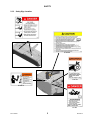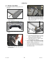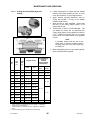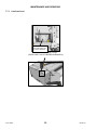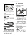
1
R85 Rotary Disc 13 Foot
Self-Propelled Windrower Header
OPERATOR’S MANUAL
Revision B
Part #169455 $15
R85 ROTARY DISC 13 FOOT SELF-PROPELLED WINDROWER HEADER
1 INTRODUCTION
This instructional manual describes the operating and maintenance procedures for the MacDon Model R85
Self-Propelled 13 foot Rotary Disc Header.
Your new MacDon Rotary Header is designed to cut, condition, and lay in windrows a wide variety of grasses and
hay crops.
CAREFULLY READ ALL THE MATERIAL PROVIDED BEFORE ATTEMPTING TO UNLOAD, ASSEMBLE, OR
USE THE MACHINE.
Use this manual as your first source of information about the machine. If you follow the instructions given in this
manual, your Mower will work well for many years. A Parts Catalog is also supplied with your new header. If you
require more detailed service information, a Service Manual is available from your dealer.
Use the Table of Contents and the Index to guide you to specific areas. Study the Table of Contents to familiarize
yourself with how the material is organized.
Keep this manual handy for frequent reference, and to pass on to new Operators or Owners. Call your Dealer if
you need assistance, information, or additional copies of this manual.
Store this Operator’s Manual and the Parts Catalog in the manual storage case located at the right end of the
header.
RECORD THE SERIAL NUMBER OF THE HEADER.
___________________________________________
Serial Number plate is located on the top surface at the right end
of the header.
Published: February, 2011
Form 169455
1
Revision B
TABLE OF CONTENTS
Section/Title
Page
1 INTRODUCTION ............................................................................................................................................... 1 2 SAFETY ............................................................................................................................................................ 4 2.1 SAFETY ALERT SYMBOL ....................................................................................................................... 4 2.2 SIGNAL WORDS ...................................................................................................................................... 4 2.3 SAFETY SIGNS ........................................................................................................................................ 4 2.3.1 Safety Sign Installation ....................................................................................................................... 4 2.3.2 Safety Sign Location ........................................................................................................................... 5 2.4 GENERAL SAFETY .................................................................................................................................. 7 3 DEFINITIONS .................................................................................................................................................... 9 4 COMPONENT IDENTIFICATION ................................................................................................................... 10 5 SPECIFICATIONS .......................................................................................................................................... 11 6 OPERATION ................................................................................................................................................... 12 6.1 OWNER/OPERATOR RESPONSIBILITIES ........................................................................................... 12 6.2 OPERATIONAL SAFETY ....................................................................................................................... 12 6.3 PRE-SEASON CHECK........................................................................................................................... 14 6.4 DAILY START-UP CHECK ..................................................................................................................... 14 6.5 HEADER ATTACHMENT ....................................................................................................................... 15 6.5.1 M205 Windrower............................................................................................................................... 16 6.5.2 M200 Windrower............................................................................................................................... 18 6.5.3 M150 Windrower............................................................................................................................... 20 6.6 HEADER DETACHMENT ....................................................................................................................... 22 6.6.1 M205 Windrower............................................................................................................................... 22 6.6.2 M200 Windrower............................................................................................................................... 24 6.6.3 M150 Windrower............................................................................................................................... 26 6.7 BREAK-IN PERIOD ................................................................................................................................ 27 6.8 SHUTDOWN PROCEDURE................................................................................................................... 27 6.9 TRANSPORTING HEADER ................................................................................................................... 27 6.10 HEADER OPERATION........................................................................................................................... 28 6.10.1 Header Flotation ............................................................................................................................... 28 6.10.2 Roll Gap ............................................................................................................................................ 29 6.10.3 Roll Tension ...................................................................................................................................... 31 6.10.4 Roll Timing ........................................................................................................................................ 32 6.10.5 Forming Shields ................................................................................................................................ 33 6.10.6 Header Angle .................................................................................................................................... 35 6.10.7 Cutting Height ................................................................................................................................... 36 6.10.8 Disc Speed ....................................................................................................................................... 37 6.10.9 Ground Speed .................................................................................................................................. 37 6.10.10 Double Windrowing........................................................................................................................... 38 6.10.11 Tall Crop Dividers ............................................................................................................................. 38 6.10.12 Header Pan ....................................................................................................................................... 39 6.11 HAYING TIPS ......................................................................................................................................... 40 6.11.1 Curing ............................................................................................................................................... 40 6.11.2 Topsoil Moisture ............................................................................................................................... 40 6.11.3 Weather and Topography ................................................................................................................. 40 6.11.4 Windrow Characteristics ................................................................................................................... 40 6.11.5 Driving On Windrow .......................................................................................................................... 40 6.11.6 Raking and Tedding.......................................................................................................................... 40 6.11.7 Chemical Drying Agents ................................................................................................................... 40 6.12 UNPLUGGING THE HEADER ............................................................................................................... 41 6.13 STORAGE .............................................................................................................................................. 41 Form 169455
2
Revision B
TABLE OF CONTENTS
7 MAINTENANCE AND SERVICING ................................................................................................................ 42 7.1 PREPARATION FOR SERVICING ........................................................................................................ 42 7.2 RECOMMENDED SAFETY PROCEDURES ......................................................................................... 42 7.3 MAINTENANCE SPECIFICATIONS ...................................................................................................... 43 7.3.1 Recommended Torques ................................................................................................................... 43 7.3.2 Recommended Lubricants ................................................................................................................ 46 7.3.3 Conversion Chart .............................................................................................................................. 47 7.4 HEADER LIFT CYLINDER LOCKS ........................................................................................................ 48 7.5 DRIVESHIELD ........................................................................................................................................ 48 7.6 CUTTERBAR DOORS............................................................................................................................ 48 7.7 LUBRICATION ........................................................................................................................................ 49 7.7.1 Greasing Procedure.......................................................................................................................... 49 7.7.2 Greasing Points ................................................................................................................................ 49 7.7.3 Lubricant Level ................................................................................................................................. 52 7.7.4 Sealed Bearing Installation ............................................................................................................... 53 7.8 CUTTERBAR .......................................................................................................................................... 54 7.8.1 Cutter Bar Lubrication ....................................................................................................................... 54 7.8.2 Rock Guards ..................................................................................................................................... 56 7.8.3 Disc Maintenance ............................................................................................................................. 56 7.8.4 Cutter Blades .................................................................................................................................... 58 7.8.5 Accelerators ...................................................................................................................................... 61 7.8.6 Rotary Deflectors .............................................................................................................................. 62 7.9 DRIVES................................................................................................................................................... 63 7.9.1 Conditioner Drive Belt ....................................................................................................................... 63 7.9.2 Conditioner Gearbox......................................................................................................................... 65 7.9.3 Bevel Gearbox .................................................................................................................................. 65 7.9.4 Gearbox Speed Sensor .................................................................................................................... 66 7.10 HYDRAULICS ......................................................................................................................................... 68 7.10.1 Hoses and Lines ............................................................................................................................... 68 7.10.2 Hydraulic Motor................................................................................................................................. 68 7.11 MAINTENANCE SCHEDULE ................................................................................................................. 69 7.11.1 Break-In Inspection ........................................................................................................................... 69 7.11.2 Interval Maintenance ........................................................................................................................ 70 7.11.3 Maintenance Record......................................................................................................................... 71 8 TROUBLESHOOTING .................................................................................................................................... 72 8.1 MOWER PERFORMANCE..................................................................................................................... 72 8.2 MECHANICAL ........................................................................................................................................ 74 9 OPTIONS AND ATTACHMENTS ................................................................................................................... 76 9.1 TALL CROP DIVIDER KIT...................................................................................................................... 76 9.2 CUTTERBAR REPAIR TOOL KIT .......................................................................................................... 76 9.3 DOUBLE WINDROW ATTACHMENT .................................................................................................... 76 9.4 SKID SHOE KIT ...................................................................................................................................... 76 10 UNLOADING AND ASSEMBLY ..................................................................................................................... 77 INDEX ...................................................................................................................................................................... 78
Form 169455
3
Revision B
SAFETY
2 SAFETY
WARNING
2.1 SAFETY ALERT SYMBOL
Indicates a potentially hazardous situation
that, if not avoided, could result in death or
serious injury. It is also used to alert
against unsafe practices.
CAUTION
Indicates a potentially hazardous situation
that, if not avoided, may result in minor or
moderate injury. It is also used as a
reminder of good safety practices.
This safety alert symbol indicates important
safety messages in this manual and on safety
signs on the machine.
2.3 SAFETY SIGNS
•
•
This symbol means:
•
ATTENTION!
BECOME ALERT!
YOUR SAFETY IS INVOLVED!
•
Carefully read and follow the safety message
accompanying this symbol.
2.3.1
Keep safety signs clean and legible at all
times.
Replace safety signs that are missing or
become illegible.
If original parts on which a safety sign was
installed are replaced, be sure the repair
part also bears the current safety sign.
Safety signs are available from your Dealer
Parts Department.
Safety Sign Installation
a. Be sure the installation area is clean and dry.
b. Decide on the exact location before you remove
the decal backing paper.
c. Remove the smaller portion of the split backing
paper.
d. Place the sign in position and slowly peel back
the remaining paper, smoothing the sign as it is
applied.
e. Small air pockets can be smoothed out or
pricked with a pin.
WHY IS SAFETY IMPORTANT TO YOU?
ACCIDENTS DISABLE AND KILL.
ACCIDENTS COST.
ACCIDENTS CAN BE AVOIDED.
2.2 SIGNAL WORDS
Note the use of the signal words DANGER,
WARNING, and CAUTION with safety
messages. The appropriate signal word for each
message has been selected using the following
guidelines:
DANGER
Indicates
an
imminently
hazardous
situation that, if not avoided, will result in
death or serious injury.
Form 169455
4
Revision B
SAFETY
2.3.2
Safety Sign Location
2 PLCS #148829
#109843
#32738
#134070
#170B
Form 169455
5
Revision B
SAFETY
1 PLC - BOTH SIDES
#142909
Form 169455
1 PLC #36651
6
Revision B
SAFETY
2.4 GENERAL SAFETY
CAUTION
The following are general farm safety
precautions that should be part of your
operating procedure for all types of
machinery:
•
Protect yourself.
•
When
assembling,
operating
and
servicing machinery, wear all the
protective clothing and personal safety
devices that COULD be necessary for the
job at hand. Don't take chances.
•
•
Provide a first-aid kit for use in case of
emergencies.
•
Keep a fire extinguisher on the machine.
Be sure the extinguisher is properly
maintained and be familiar with its proper
use.
•
Keep young children
machinery at all times.
•
Be aware that accidents often happen
when the operator is tired or in a hurry to
get finished. Take the time to consider
the safest way. Never
ignore warning signs of
fatigue.
•
Wear close-fitting clothing
and cover long hair. Never
wear dangling items such
as scarves or bracelets.
•
Keep hands, feet, clothing and hair away
from moving parts. Never attempt to
clear obstructions or objects from a
machine while the engine is running.
•
Keep all shields in place. Never alter or
remove safety equipment. Make sure
driveline
guards
can
rotate
independently of the shaft and can
telescope freely.
•
Use only service and repair parts made
or
approved
by
the
equipment
manufacturer. Substituted parts may not
meet strength, design, or safety
requirements.
•
Do
not
modify
the
machine.
Unauthorized modifications may impair
the function and/or safety and affect
machine life.
(continued next page)
You may need:
•
•
•
•
•
•
a hard hat.
protective shoes with slip resistant
soles.
protective glasses or goggles.
heavy gloves.
wet weather gear.
respirator or filter mask.
A
B
•
Form 169455
hearing protection. Be aware that
prolonged exposure to loud noise
can cause impairment or loss of
hearing. Wearing a suitable hearing
protective device such as ear muffs
(A) or ear plugs (B) protects against
objectionable or loud noises.
7
away
from
Revision B
SAFETY
•
Stop engine, and remove key from
ignition before leaving Operator's seat
for any reason. A child or even a pet
could engage an idling machine.
•
Keep the area used for servicing
machinery clean and dry. Wet or oily
floors are slippery. Wet spots can be
dangerous when working with electrical
equipment. Be sure all electrical outlets
and tools are properly grounded.
•
Use adequate light for the job at hand.
•
Keep machinery clean. Do not allow oil or
grease to accumulate on service
platforms, ladders or controls. Clean
machines before storage.
•
Never use gasoline, naphtha or any
volatile material for cleaning purposes.
These materials may be toxic and/or
flammable.
•
When storing machinery, cover sharp or
extending components to prevent injury
from accidental contact.
Form 169455
8
Revision B
3 DEFINITIONS
The following terms may be used in this manual:
TERM
DEFINITION
API
American Petroleum Institute
ASTM
American Society Of Testing And Materials
Cab-Forward
Windrower operation with the operator and cab facing in the direction of travel.
Center-link
A hydraulic cylinder or turnbuckle type link between the header and the machine
that tilts the header.
Engine-Forward
Windrower operation with the operator and engine facing in the direction of travel.
Header or Rotary Header
A machine that cuts and conditions hay, and is attached to a windrower.
Mower Conditioner
A machine that cuts and conditions hay, and is pulled by an agricultural tractor.
rpm
Revolutions Per Minute
SAE
Society Of Automotive Engineers
Self-Propelled Windrower
Self-propelled machine consisting of a power unit with a header and conditioner.
Sickle or Knife
A cutting device which uses a reciprocating cutter.
Tractor
Ag type tractor.
Truck
A four-wheel highway/road vehicle weighing no less than 7500 lb (3400 kg).
Windrower
Power unit of a self-propelled auger header.
Form 169455
9
Revision B
4 COMPONENT IDENTIFICATION
HYDRAULIC HOSES
TO SP WINDROWER
FRONT CURTAINS
HOSE SUPPORTS
CONDITIONER ROLLS
8 DISC CUTTERBAR
DOORS
DRIVESHIELD
Form 169455
BAFFLE CONTROL
DRIVE MOTOR
ROTARY
DEFLECTOR
MANUAL STORAGE CASE
HEADER BOOT
10
BAFFLE
Revision B
5 SPECIFICATIONS
HEADER MODEL
R85 - 13 FT
FRAME AND STRUCTURE
Transport Width
13 ft-0 in. (3952 mm)
Weight (estimated)
3000 lb (1360 kg)
Carrier
MacDon M150, M200, M205 SP Windrowers
Lighting
None
Manual Storage
Header Mounted Storage Case
CUTTERBAR
8
Quantity Of Cutting Discs
Two 18 Degrees Bevel Down Reversible
Blades Per Disc
Disc Speed
1800 - 2600 rpm
Blade Tip Speed Range
131 - 189 mph (59.2 - 85.5 m/s)
Effective Cutting Width
12 ft-9.5 in. (3895 mm)
Cutting Height
1 to 3 in. (25 - 75 mm)
3.37 quarts US (3.25 liters)
Lubricant Capacity (Maximum)
Cutting Angle Range
0 - 8 Degrees Below Horizontal
Geartrain Protection
Shearable Disc Spindles
Deflectors
Two Rotary Converging Cages
Shoes
Two Adjustable
DRIVE
Type
Max. Power
Developed
M200 & M205
6.4 cu in. (106 cc) Heavy Duty Hydraulic Motor
M150
4.6 cu in. (75 cc) Heavy Duty Hydraulic Motor
M205
231 hp (174 kW)
M200
195 hp (146 kW)
M150
130 hp (97 kW)
Connections
Direct Coupled (Optional Quick Coupler Connection)
Normal Operating Pressure
4000 psi (27.58 MPa)
CONDITIONER
Drive
Bevel Gearbox To Belt Driven Enclosed Conditioner Timing Gearbox And Driveline.
Bevel Gearbox Lub. Capacity
13.5 oz. (400 ml)
Conditioner Gearbox Lub. Cap.
Lubricated for Life
Roll Type
Roll Diameter
Intermeshing Steel Bars
9.0 in. (229 mm) / 7.0 in. (179 mm) OD Tube
Roll Length
118 in. (3000 mm)
Roll Speed
730 - 1040 rpm
Swath Width
Forming Shields
36 - 102 in. (915 - 2540 mm)
Windrower Mounted Adjustable Forming Shield System
GROUND SPEED
16 mph (25.7 km/h)
NOTES: 1. Specifications and design are subject to change without notice or obligation to revise previously sold units.
Form 169455
11
Revision B
OPERATION
6.2 OPERATIONAL SAFETY
6 OPERATION
Follow these safety precautions:
6.1 OWNER/OPERATOR
RESPONSIBILITIES
CAUTION
•
Follow all safety and operational
instructions given in your windrower
Operator's Manual. If you do not have a
windrower manual, get one from your
dealer and read it thoroughly.
•
Never attempt to start the windrower
engine or operate the windrower except
from the operator’s seat.
•
Check the operation of all controls in a
safe clear area before starting work.
•
Do not allow riders on windrower.
•
Never start or move the machine until
you are sure all bystanders have cleared
the area.
•
Avoid travelling over loose fill, rocks,
ditches or holes.
•
Drive slowly
doorways.
•
If cutting ditch banks, use extreme
caution. If the header hits an
obstruction, the front of the windrower
will usually swerve towards the ditch.
•
When working on inclines, travel uphill
or downhill when possible.
Do
not
modify
the
machine.
Unauthorized modifications may impair
the function and/or safety and affect
machine life.
•
Never attempt to get on or off a moving
windrower.
•
•
Do not get off the windrower while the
header is in operation.
The safety information given in this
manual does not replace safety codes,
insurance needs, or laws governing
your area. Be sure your machine meets
the standards set by these regulations.
•
Stop windrower engine and remove key
before adjusting or removing plugged
material from the machine. A child or
even a pet could engage the drive.
•
Ensure that the windrower is properly
equipped to safely operate the header.
This may include adding ballast
according to Windrower Operator’s
Manual requirements for attachments of
this size and mass.
•
Check for excessive vibration and
unusual noises. If there is any indication
of trouble, shutdown and inspect the
machine. Follow proper shutdown
procedure:
- engage windrower brake.
- turn off engine and remove key.
- wait for all movement to stop.
- dismount and engage lift cylinder
stops before inspecting raised
machine.
•
Operate only in daylight or in good
artificial light.
(continued next page)
CAUTION
•
It is your responsibility to read and
understand this manual completely
before operating the windrower. Contact
your Dealer if an instruction is not clear
to you.
•
Follow all safety messages in the
manual and on safety signs on the
machine.
•
Remember that YOU are the key to
safety. Good safety practices protect
you and the people around you.
•
Before allowing anyone to operate the
windrower, for however short a time or
distance, make sure they have been
instructed in its safe and proper use.
•
Review the manual and all safety related
items with all operators annually.
•
Be alert for other operators not using
recommended
procedures
or not
following safety precautions. Correct
these mistakes immediately, before an
accident occurs.
•
Form 169455
12
through
gates
and
Revision B
OPERATION
•
Keep everyone several hundred feet
away from your operation. Ensure
bystanders are never in line with the
front or rear of the machine. Stones or
other foreign objects can be ejected
from either end with force.
•
Extreme care must be exercised to
avoid injury from thrown objects. Do
not, under any circumstances, operate
the mower conditioner when other
people are in the vicinity. Stones and
other objects can be thrown great
distances by the rotating cutting blades.
•
The cutterbar curtains are very
important to reduce the potential for
thrown objects. Always keep these
curtains down when operating the
mower conditioner. Replace the curtains
if they should become worn or
damaged.
Form 169455
13
Revision B
OPERATION
•
6.3 PRE-SEASON CHECK
You may need:
Perform the following the beginning of each
operating season:
CAUTION
•
Review the Operator's Manual to refresh
your memory on safety and operating
recommendations.
•
Review all safety signs and other decals
on the header, and note hazard areas.
•
Be sure all shields and guards are
properly installed and secured. Never
alter or remove safety equipment.
•
Be sure you understand and have
practiced safe use of all controls. Know
the
capacity and
the
operating
characteristics of the machine.
-
a hard hat.
protective glasses or goggles.
heavy gloves.
respirator or filter mask.
wet weather gear.
•
Protect against noise. Wear a
suitable hearing protective
device such as ear muffs or ear
plugs
to
protect
against
objectionable or uncomfortable
loud noises.
a. Check the machine for leaks or any parts that
are missing, broken, or not working correctly.
•
Check the first aid kit and fire
extinguisher. Know where they are and
how to use them.
a. Lubricate machine completely. Refer to Section
7.7 LUBRICATION.
b. Perform all annual maintenance. See Section
7.11 MAINTENANCE SCHEDULE.
NOTE
Use proper procedure when searching for
pressurized fluid leaks. Refer to Section
7.10 HYDRAULICS.
b. Clean all reflective surfaces on the machine.
c. Perform all Daily maintenance. Refer to Section
7.11 MAINTENANCE SCHEDULE.
6.4 DAILY START-UP CHECK
CAUTION
•
Be sure windrower and header are
properly attached, all controls are in
neutral and windrower brake is
engaged.
•
Clear the area of other persons, pets
etc.
Keep
children
away
from
machinery. Walk around the windrower
to be sure no one is under, on or close
to it.
•
Wear close fitting clothing and
protective shoes with slip resistant
soles.
•
Remove foreign objects from
machine and surrounding area.
•
As well, carry with you any protective
clothing and personal safety devices
that COULD be necessary through the
day. Don't take chances.
the
•
Form 169455
14
Revision B
OPERATION
6.5 HEADER ATTACHMENT
a. If not installed, attach the forming shield to the
windrower:
D
C
A
4. Lift the aft end of the forming shield, and
attach straps (C) to pins (D) on windrower
frame. Install washer and hairpin to secure
strap. Use the "middle" hole, and adjust
height to suit the crop.
1. Remove the two clevis pins (A) from forming
shield forward end.
G
E
F
2. Position forming shield under the windrower
frame.
BOTH SIDES
5. Set forming shield side deflectors to desired
width by re-positioning adjuster bars (E).
Use same hole location on both sides.
6. Adjust fluffer shield (F) to "middle" position.
Loosen handles (G) if required.
b. Attach the R85 header to the Windrower. Refer
to the MacDon Self-Propelled Windrower
Operator’s Manual, and then return to this
manual to complete the attachment.
c. Connect the hydraulics and electrical harness.
See applicable section in the following pages for
your windrower model.
B
A
3. Locate forming shield onto spacers (B) on
windrower legs, and secure with clevis pins
(A) and lynch pin.
Form 169455
15
Revision B
OPERATION
6.5.1
d. If optional couplers and lock are installed on
hoses and lines, proceed as follows. Otherwise,
proceed to step e.
1. If installed, remove coupler lock as follows:
M205 Windrower
DANGER
Stop engine, and remove key from ignition
before leaving Operator's seat for any
reason. A child or even a pet could engage
an idling machine.
E
D
i.
ii.
Remove lynch pin (D), and open up
coupler lock (E).
Remove lock from coupler.
a. Move windrower left side platform to "open"
position.
F
A
F
C
2. Position hose couplers against mating
couplers on windrower, and screw sleeves
(F) onto mating receptacles.
3. Hand-tighten both coupler sleeves (F).
B
G
H
b. Route the hose bundle (A) from the header,
under the windrower frame, and insert pin (B)
into hole in windrower frame.
c. Place hoses on support (C).
Form 169455
4. Locate lock onto couplers so that retainer
(G) locates on fitting adjacent to the sleeve
on each coupler. Retainer can be adjusted
by loosening bolts (H). Tighten bolts after
adjusting.
(continued next page)
16
Revision B
OPERATION
g. Connect electrical harness to connector (P)
(located beside the forward valve block on the
windrower).
J
F
K
F
5. Lower holder (J) onto sleeves (F) so that
flats locate on holder.
Holder can be
adjusted by loosening bolts (K). Tighten
bolts after adjusting.
h. Move windrower platform to "closed" position.
L
D
6. Insert lynch pin (D) to secure lock.
7. Remove caps and plugs from the two large
hoses and lines.
8. Attach case drain hose coupler at (L).
9. Proceed to step g.
P
M
O
N
e. Connect large hoses to the lines at (M) and (N)
as shown. Torque fittings to 135 ft·lbf (183 N·m).
f. Attach case drain hose coupler at (O).
Form 169455
17
Revision B
OPERATION
6.5.2
M200 Windrower
DANGER
Stop engine, and remove key from ignition
before leaving Operator's seat for any
reason. A child or even a pet could engage
an idling machine.
d. Check that hose support is positioned so that
lower bolt is in "forward" hole, and support is
positioned as shown. Loosen bolts, and adjust
as required.
C
E
D
A
B
C
a. Disengage and rotate lever (A) counter
clockwise to "fully up" position.
b. Remove cap (B) securing electrical connector to
frame.
e. Route hose bundle (C) from windrower through
support (D) on header.
f. Route header return and pressure hose bundle
(E) through support (D) on header, to windrower.
C
A
F
c.
Move hose bundle (C) from windrower, and rest
bundle on the header.
g. Lower and lock lever (A).
h. Secure hose bundles with three cinch straps (F).
(continued next page)
Form 169455
18
Revision B
OPERATION
PRESSURE
RETURN
i.
Move windrower left side platform to "open"
position.
CASE DRAIN
l.
Connect the three hoses from windrower to the
fittings on the header as shown.
m. Assemble electrical connector as shown.
RETURN
PRESSURE
MIDDLE VALVE BLOCK
j.
k.
Connect two hose bundle from header to
"middle" valve block as shown.
Remove caps and plugs on hoses from
windrower and lines on header
Form 169455
n. Move platform to "closed" position.
19
Revision B
OPERATION
6.5.3
M150 Windrower
DANGER
Stop engine, and remove key from ignition
before leaving Operator's seat for any
reason. A child or even a pet could engage
an idling machine.
d. Check that hose support is positioned so that
lower bolt is in "forward" hole, and support is
positioned as shown. Loosen bolts, and adjust
as required.
C
D
C
E
A
B
a. Disengage and rotate lever (A) counter
clockwise to "fully up" position.
b. Remove cap (B) securing electrical connector to
frame.
e. Route hose bundle (C) from windrower through
support (D) on header.
f. Route header hose (E) through support (D) on
header, to windrower.
C
c.
Move hose bundle (C) from windrower, and rest
bundle on the header.
g. Move windrower left side platform to "open"
position.
(continued next page)
Form 169455
20
Revision B
OPERATION
F
h. Connect single hose (E) from header to coupler
(F) on "middle" valve block as shown
i. Remove caps and plugs on hoses from
windrower and lines on header.
m. Move windrower platform to "closed" position.
PRESSURE
RETURN
CASE DRAIN
j.
k.
Connect the three hoses from windrower to the
fittings on the header as shown.
Connect harness from windrower to electrical
connector.
G
E
A
l.
Lower and lock lever (A). Secure hose (E) with
three cinch straps (G).
Form 169455
21
Revision B
OPERATION
6.6 HEADER DETACHMENT
6.6.1
D
M205 Windrower
a. Lower header to ground. If ground is soft, place
blocks under header.
b. Stop engine, and remove key.
2. Remove lynch pin (C), and open up coupler
lock (D).
3. Remove lock from couplers.
c.
Move LH (cab-forward) platform to rear of
windrower.
E
A
4. Unscrew sleeves (E) on couplers, and
separate couplers.
5. Install caps and plugs on open lines.
d. Disconnect electrical harness at (A).
e. If couplers and coupler lock are installed on
lines, proceed as follows. Otherwise, proceed to
step f.
D
B
C
C
6. Attach coupler lock (D) to hoses, and secure
with lynch pin (C).
7. Proceed to step g.
(continued next page)
1. Disconnect ½ inch hose (B) from windrower
coupler.
Form 169455
22
Revision B
OPERATION
F
H
G
f.
Disconnect hoses from lines (F), (G), and (H) on
windrower. Install caps and plugs on open lines.
i.
j.
Move maintenance platform to "closed" position.
Detach the header from the windrower. Refer to
the
MacDon
Self-Propelled
Windrower
Operator’s Manual.
K
J
g. Remove hose support (J) from windrower frame.
h. Route hoses (K) and electrical harness onto
header.
Form 169455
23
Revision B
OPERATION
6.6.2
M200 Windrower
A
C
DANGER
Stop engine, and remove key from ignition
before leaving Operator's seat for any
reason. A child or even a pet could engage
an idling machine.
B
a. Lower header to ground. If ground is soft, place
blocks under header.
b. Stop engine, and remove key.
e. Raise lever (A), and undo Velcro® straps (B).
f. Move hose bundle (C) to store on header
g. Install caps on connectors and hose ends if
equipped.
h. At the header, disconnect electrical connector by
turning collar counter clockwise, and pulling
connector to disengage.
PRESSURE
c.
Move LH (cab-forward) platform to rear of
windrower.
RETURN
RETURN
CASE DRAIN
PRESSURE
i.
Disconnect the two drive couplers, and case
drain coupler on header.
(continued next page)
d. Disconnect the two hydraulic couplers from
windrower valve.
Form 169455
24
Revision B
OPERATION
A
D
E
j.
k.
l.
Move hose bundle from header, and locate on
windrower LH side with hoses in support (D).
Rotate lever (A) clockwise, and push to engage
bracket.
Locate electrical harness through support (D),
and attach cap to electrical connector (E).
m. Move windrower platform back to "closed"
position.
n. Detach header from windrower. Refer to the
Self-Propelled Windrower Operator’s Manual.
Form 169455
25
Revision B
OPERATION
6.6.3
h. At the header, disconnect electrical connector by
turning collar counter clockwise, and pulling
connector to disengage.
M150 Windrower
DANGER
Stop engine, and remove key from ignition
before leaving Operator's seat for any
reason. A child or even a pet could engage
an idling machine.
PRESSURE
a. Lower header to ground. If ground is soft, place
blocks under header.
b. Stop engine, and remove key.
RETURN
CASE DRAIN
i.
Disconnect the two drive couplers, and case
drain coupler on header.
E
c.
Move LH (cab-forward) platform to rear of
windrower.
A
j.
k.
l.
d. Disconnect the hydraulic coupler from windrower
valve.
D
Move hose bundle from header, and locate on
windrower LH side with hoses in support (D).
Rotate lever (A) clockwise, and push to engage
bracket.
Locate electrical harness through support (D),
and attach cap to electrical connector (E).
B
C
A
m. Move windrower platform back to "closed
position".
n. Detach header from windrower. Refer to the
Self-Propelled Windrower Operator’s Manual.
e. Raise lever (A) and undo Velcro® straps (B).
f. Move hose (C) to store on header.
g. Install caps on connectors and hose end if
equipped.
Form 169455
26
Revision B
OPERATION
6.7 BREAK-IN PERIOD
a. After attaching header to windrower for the first
time, operate the machine slowly for 5 minutes,
watching
and
listening
FROM
THE
WINDROWER SEAT for binding or interfering
parts.
NOTE
Until you become familiar with the sound
and feel of your new header, be extra alert
and attentive.
WARNING
Before investigating an unusual sound or
attempting to correct a problem, shut off
windrower, engage parking brake and
remove key.
b. Perform the items specified in Section 7.11.1
Break-In Inspection.
6.8 SHUTDOWN PROCEDURE
CAUTION
Before leaving the windrower seat for any
reason:
•
Park on level ground if possible.
•
Lower the header fully.
•
Place
ground
N-DETENT.
•
Stop engine, and remove key from
ignition.
•
Wait for all movement to stop.
speed
control
in
6.9 TRANSPORTING HEADER
Refer to your MacDon Self-Propelled Windrower
Operator’s Manual for transporting headers
when attached to the windrower.
Form 169455
27
Revision B
OPERATION
6.10 HEADER OPERATION
6.10.1
Satisfactory operation of the header in all
situations requires making proper adjustments to
suit various crops and conditions.
Header flotation springs are normally set so that
95 - 105 lbf (426 - 471 N) is required to lift either
end of the header "just" off the ground. In rough
or stony conditions, it may be desirable to
maintain a lighter setting to protect cutting
components.
Correct operation reduces crop loss and
increases productivity. As well, proper
adjustments and timely maintenance will
increase the length of service you receive from
the machine.
NOTE
When float setting is light, it may be
necessary to use a slower ground speed
to avoid excessive bouncing and leaving a
ragged cut.
The variables listed below and detailed on the
following pages will affect the performance of
the header. You will quickly become adept at
adjusting the machine to give you the desired
results. Most of the adjustments have been set
at the factory but if desired, the settings can be
changed to suit crop conditions.
VARIABLE
SECTION
Header Flotation
Roll Gap
Roll Tension
Roll Timing
Forming Shields
Header Angle
Cutting Height
Disc Speed
Ground Speed
Double Windrowing
6.10.1
6.10.2
6.10.3
6.10.4
6.10.5
6.10.6
6.10.7
6.10.8
6.10.9
6.10.10
Header Flotation
a. Set the float fine adjustment to mid-range with
the windrower float adjustment system in the
cab. Refer to your M Series Self-Propelled
Windrower Operator’s Manual.
DANGER
Stop engine, and remove key from ignition
before leaving operator's seat for any
reason. A child or even a pet could engage
an idling machine.
b. Check float by grasping the front corner of
header and lifting. The force to lift should be
95 - 105 lbf (426 - 471 N), and should be
approximately the same at both ends.
c. Perform the following steps to adjust the float (if
necessary):
1. Raise the header fully, shutdown the engine,
and remove the key.
A
2. Turn drawbolt (A):
•
clockwise to increase float (makes
header lighter), or
•
counter clockwise to decrease float
(makes header heavier).
3. Re-check the float.
Form 169455
28
Revision B
OPERATION
6.10.2 Roll Gap
Steel rolls "condition" the crop by crimping and
crushing the stem in several places. This allows
moisture release for quicker drying. The degree
to which the crop is conditioned as it passes
through the rolls is controlled by roll gap, which
is factory-set at 0.5 inch (13 mm).
A
Correct conditioning of alfalfa, clover and other
legumes is usually indicated when 90% of the
stems show cracking, but no more than 5% of
the leaves are damaged. Set enough roll gap to
achieve this result.
B
B
A
d. At each end of rolls, loosen nuts (A), and slide
cover (B) “upwards” to expose observation hole.
A larger gap (up to 1 inch (25 mm)) may be
desirable in thick stemmed cane-type crops;
however, too large a gap may cause feeding
problems.
ROLL GAP
Grass type crops may require less gap for
proper feeding and conditioning.
If settings below the factory setting are used, it is
recommended that the actual gap be visually
checked.
To check roll gap, proceed as follows:
DANGER
LEFT END
Stop engine, and remove key from ignition
before leaving Operator's seat for any
reason. A child or even a pet could engage
an idling machine.
a. Lower header fully.
b. Stop engine, and remove key.
ROLL GAP
RIGHT END
e. Check the gap at each end of the rolls to verify
setting, and adjust as necessary.
IMPORTANT
c.
Open driveshield at left end of header.
Section 7.5 DRIVESHIELD.
Roll timing is critical when the roll gap is
decreased because:
See
•
Conditioning is affected, and
• The bars may contact each other.
Refer to Section 6.10.4 Roll Timing.
f. Re-position covers (B), and tighten nuts (A).
g. Close driveshield.
Form 169455
29
Revision B
OPERATION
6.10.2.1 Roll Gap Adjustment
a. Lower header fully.
DANGER
Stop engine, and remove key from ignition
before leaving Operator's seat for any
reason. A child or even a pet could engage
an idling machine.
b. Stop engine, and remove key.
0.75 in. (19 mm)
A
B
c.
Loosen and “back off” upper jam-nut (A) - both
sides of conditioner.
d. To increase roll gap, turn lower nut (B)
clockwise.
NOTE
The amount of thread protruding through
jam-nut indicates roll gap. Factory setting
is 0.75 in. (19 mm) which equates to 0.50
in (13 mm) of roll gap.
NOTE
When adjusting roll gap, be sure that the
thread protruding is the same on both
sides of the conditioner roll to achieve a
consistent gap across the rolls.
e. To decrease the roll gap, turn lower nut (B)
counter clockwise.
f. Tighten jam-nuts (A), both sides.
Form 169455
30
Revision B
OPERATION
6.10.3 Roll Tension
C
The roll tension (the force holding the rolls
together) is factory-set to “maximum”, and is
adjustable.
A
Heavy crops or tough forage that tend to
separate the rolls require the maximum roll
tension to ensure that material is sufficiently
crimped.
B
Light alfalfa and short grasses would require
less roll tension to lessen over-conditioning.
6.10.3.1 Roll Tension Adjustment
LH SHOWN
DANGER
c.
To increase the roll tension, loosen jam-nut (A),
and turn the spring draw-bolt (B) clockwise to
tighten the spring (C).
d. Repeat above step for opposite end of roll.
e. To decrease the roll tension, turn the spring
draw-bolts (B) counter clockwise to loosen the
springs.
Stop engine, and remove key from ignition
before leaving Operator's seat for any
reason. A child or even a pet could engage
an idling machine.
a. Lower header to ground, shutdown windrower,
and remove key.
IMPORTANT
Turn each bolt equal amounts. Each turn
of the bolt changes the roll tension by
approximately 6.5 lbf (29 N).
f. Tighten jam-nut (A) after adjusting tension.
g. Close driveshield.
b. Open driveshield at LH end of header.
Section 7.5 DRIVESHIELD.
Form 169455
See
31
Revision B
OPERATION
6.10.4.1 Roll Timing Adjustment
6.10.4 Roll Timing
Adjust roll timing, if necessary, as follows:
For proper conditioning, the rolls must be
properly timed with each steel bar on one roll
centered between two bars of the other roll as
shown. The factory setting should be suitable
for most crop conditions.
IMPORTANT
Roll timing is critical when the roll gap is
decreased because:
•
Conditioning is affected, and
•
The bars may contact each other.
A
a. Loosen four bolts (A) in slots of yoke plate on
upper roll universal shaft.
b. Manually rotate upper roll it stops. Make a mark
on yoke flange to align with the center of one of
the bolt (A) heads.
c. Manually rotate upper roll in opposite direction
until it stops. Make a second mark on yoke
flange to align with the bolt.
d. Determine the center between the two marks,
and mark a third line on the yoke flange.
e. Rotate the upper roll until the bolt “lines up” with
the third line.
f. Tighten bolts (A) to secure the position.
CROP
X
To check roll timing ‘X’, proceed as follows:
DANGER
Stop engine, and remove key from ignition
before leaving Operator's seat for any
reason. A child or even a pet could engage
an idling machine.
a. Lower header fully, stop engine, and remove
key.
b. Open the driveshield.
See Section 7.5
DRIVESHIELD.
c. Examine roll timing (distance ‘X’) at each end of
the rolls with the header fully lowered. Each
steel bar on one roll should be centered
between two bars of the other roll so that
distance ‘X’ is approximately equal on both
sides of the bar.
Form 169455
32
Revision B
OPERATION
6.10.5.1 Side Deflectors
6.10.5 Forming Shields
The position of the side deflectors control the
width and placement of the windrow.
WARNING
DANGER
Keep everyone several hundred feet away
from your operation. Ensure bystanders
are never in line with the front or rear of the
machine. Stones or other foreign objects
can be ejected from either end with force.
Stop engine, and remove key from ignition
before leaving Operator's seat for any
reason. A child or even a pet could engage
an idling machine.
The position of the forming shields controls the
width and placement of the windrow. The
decision on forming shield position should be
based on the following factors:
•
•
•
•
weather conditions (rain, sun, humidity,
wind),
type and yield of crop,
drying time available, and
method of processing (bales, silage, "greenfeed")
A wider windrow will generally dry faster and
more evenly, resulting in less protein loss. Fast
drying is especially important in areas where the
weather allows only a few days to cut and bale.
Refer to Section 6.11 HAYING TIPS, for more
information.
B
A
BOTH SIDES
a. Set forming shield side deflectors (A) to desired
width by re-positioning adjuster bars (B) in holes
in forming shield cover. To ensure windrow
placement is centered, adjust both side
deflectors to the same position.
A narrower windrow may be preferred for ease
of pick-up, and when drying is not critical, for
example, when cutting for silage or "green-feed".
C
b. If side deflector attachment is too tight or too
loose, tighten or loosen nut (C) as required.
Form 169455
33
Revision B
OPERATION
6.10.5.3 Baffle
6.10.5.2 Rear Deflector (Fluffer Shield)
The baffle (F) determines the width and height of
the windrow.
The rear deflector slows the crop exiting the
conditioner rolls, directs the flow downward, and
"fluffs" the material.
It is located immediately behind and above the
conditioning rolls, and can be positioned to:
Adjust the deflector as follows:
DANGER
Stop engine, and remove key from ignition
before leaving Operator's seat for any
reason. A child or even a pet could engage
an idling machine.
•
Direct the crop flow into the forming shield
for narrow and moderate width windrows, or
•
Direct crop downward to form a wide swath.
Adjust the baffle as follows:
DANGER
Stop engine, and remove key from ignition
before leaving Operator's seat for any
reason. A child or even a pet could engage
an idling machine.
E
D
F
BOTH SIDES
a. For more crop control in light material, lower the
deflector (D) by pushing "down" on one side of
the deflector, and then on the other side.
G
NOTE
Locking handles (E) are located at either
end of the deflector, and may be loosened
slightly.
H
b. For heavier crops, raise the deflector by pulling
"up" on one side, and then on the other side.
NOTE
For even windrow formation, be sure the
deflector is not twisted.
c.
a. Pull lever (G) to disengage from bracket (H), and
move lever:
Tighten handles (E) to secure deflector position.
•
"forward" to raise baffle (F), or
•
"backward" to lower baffle (F).
b. Release lever into bracket.
Form 169455
34
Revision B
OPERATION
6.10.6 Header Angle
Header (or cutterbar) angle can be varied from
0 - 8° below horizontal.
Choose an angle that maximizes performance
for your crop and field conditions.
A flatter angle provides better clearance in stony
conditions, while a steeper angle is required in
down crops for better lifting action.
The header angle can be hydraulically adjusted
from the windrower cab using hydraulic cylinder
without shutting down the windrower.
Refer to your MacDon Self-Propelled Windrower
Operator’s Manual.
Form 169455
35
Revision B
OPERATION
6.10.7 Cutting Height
Set up the header as follows:
Cutting height is determined by a combination of
the angle of the cutterbar/header, and the skid
shoe settings.
DANGER
To avoid bodily injury or death from
unexpected start-up or fall of raised
machine: stop engine, remove key, and
engage header lift cylinder stops before
going under machine for any reason.
Cutting height should be adjusted for optimum
cutting performance without allowing excessive
build-up of mud and soil inside the header that
can lead to poor crop flow and increased wear
on cutting components.
a. Raise header fully, stop engine, and remove
key.
Choose an angle that maximizes performance
for your crop and field conditions. Refer to
Section 6.10.6 Header Angle.
Optional adjustable skid shoes are available to
also provide different cutting heights as
described below:
•
Lowering the skid shoes or decreasing
header angle increases the cutting
height. This may be desirable in stony
conditions, to reduce damage to cutting
components. Also, a longer stubble
length helps material dry faster.
•
Raising the skid shoes and increasing
header angle allows the crop to be
“shaved”.
A
b.
c.
d.
e.
f.
Remove bolts (A).
Raise or lower skid shoe.
Re-install bolts (A).
Repeat for skid shoe at opposite end of header.
Check header float as described in Section
6.10.1 Header Flotation.
g. Adjust header angle to desired working position
using the machine's header angle controls. If
angle is not critical, set it to "mid-position".
Refer to Section 6.10.6 Header Angle for more
information.
To minimize damage to cutterbar components,
scooping soil, or soil build-up at the cutterbar in
damp conditions, header float should be set as
light as possible without causing excessive
bouncing.
When the float setting is light, it may be
necessary to use a slower ground speed to
avoid excessive bouncing and leaving a ragged
cut.
Form 169455
36
Revision B
OPERATION
6.10.9
6.10.8 Disc Speed
The disc header can be used to cut a variety of
crops.
CAUTION
Reduce speed when turning, crossing
slopes, or when travelling over rough
ground.
For the best cutting results, a range of disc
speeds is recommended for each type of crop
and condition.
a. Choose a ground speed that allows the cutterbar
and conditioner to cut the crop smoothly and
evenly. Try different combinations of header
speed and ground speed to suit your specific
crop. Refer to your MacDon Self-Propelled
Windrower Operator’s Manual for changing
ground speed.
b. In tough cutting conditions (such as native
grasses) the disc speed will need to be
increased.
c. In light crops the header speed can be reduced
while maintaining ground speed.
See table below.
CROP
Alfalfa
Sudan,
Sorghum,
Haygrazer,
Timothy
Short Grass
CONDITION
DISC RPM
Heavy
2300 - 2500
Light
1600 - 2000
Tall and
Stemmy
2300 - 2500
Dense
2500
Thin
1800 - 2000
Ground Speed
NOTE
Disc speeds are set and adjusted from the cab
without shutting down the windrower.
Operating the header at the minimum disc
speed will extend the wear life of cutting
components.
Refer to your MacDon Self-Propelled Windrower
Operator’s Manual.
d. The chart below indicates the relationship
between ground speed and area cut for a 13 FT
header.
Example: At ground speed of 13 mph (21 km/h),
the area cut would be approximately 20 acres
(8 hectares) per hour.
kilometers/hour
3.2
4.8
6.4
8.0
9.7 11.3 12.9 14.5 16.1 17.7 19.3 20.9 22.5 24.1 25.7
14
30
12
25
10
20
8
15
6
10
4
5
2
0
0
1
2
3
4
5
6
7
8
9
hectares/hour
acres/hour
1.6
35
10 11 12 13 14 15 16
miles/hour
Form 169455
37
Revision B
OPERATION
6.10.11 Tall Crop Dividers
6.10.10 Double Windrowing
The tall crop dividers (one on each end of
header) assist in clean crop dividing and
cutterbar entry in tall crops.
They are not adjustable, but can easily be
removed as follows:
DANGER
Stop engine, and remove key from ignition
before leaving Operator's seat for any
reason. A child or even a pet could engage
an idling machine.
a. Lower header to ground, shutdown windrower,
and remove key.
If your windrower is equipped with the Double
Windrow Attachment (DWA), refer to MacDon M
Series Windrower Double Windrow Attachment
Manual (Form 169216) for operating and
maintenance instructions.
The manual is shipped with the DWA Kit.
b. Open cutterbar doors.
B
A
c.
Remove the four bolts (A), and remove deflector
(B).
d. Re-install the four bolts.
e. Close cutterbar doors.
Form 169455
38
Revision B
OPERATION
6.10.12 Header Pan
The header pan is located behind the cutterbar,
and helps prevent material loss and wrapping in
certain crops, such as grass seed, oats, and tall
stalky crops.
In conditions where more soil and stones are
being picked up by the cutterbar, it may be
desirable to remove the pan to allow the debris
to fall out before being fed into the conditioner.
DANGER
Stop engine, and remove key from ignition
before leaving Operator's seat for any
reason. A child or even a pet could engage
an idling machine.
Removal:
a. Raise header fully, stop engine, and remove
key.
b. Engage header lift cylinder stops.
c.
Raise cutter bar doors for access to the bolts
securing pan to frame.
A
B
d. Remove six bolts (A) securing pan (B) to
header, and remove pan.
Installation:
a. Locate pan (B) under header frame, and hold in
place.
b. Install six 1/2 in. x 1 carriage bolts (A) and
flanged locknuts. Tighten hardware.
Form 169455
39
Revision B
OPERATION
6.11.4 Windrow Characteristics
6.11 HAYING TIPS
It is recommended that a windrow with the
following characteristics be produced. Refer to
Section 6.10 HEADER OPERATION for
instructions on adjusting the header.
6.11.1 Curing
a. A quick cure will maintain top quality because:
•
Protein is lost for each day hay lies on the
ground,
• The sooner the cut hay is harvested, the
earlier the start for next growth.
b. Leaving the windrow as wide and thin as
possible makes for the quickest curing.
c. The cured hay should be baled as soon as
possible.
6.11.2 Topsoil Moisture
a. On wet soil, the general rule of "wide and thin"
does not apply. A narrower windrow will dry
faster than hay left flat on wet ground.
b. When the ground is wetter than the hay,
moisture from the soil is absorbed by the hay
above it. Determine topsoil moisture level before
cutting. Use a moisture tester or estimate level:
LEVEL
% MOISTURE
CONDITION
Wet
Over 45%
Soil is Muddy
Damp
25 - 45%
Shows Footprints
Dry
Under 25%
Surface is Dusty
ADVANTAGE
High and Fluffy
The movement of air through the
windrow is more important to the
curing process than is direct
sunlight.
Consistent
Formation,
Not Bunchy
Permits an even flow of material
into the baler, chopper etc.
Even Distribution of
Material Across
Windrow
Results in even and consistent
bales to minimize handling and
stacking problems.
Properly
Conditioned
Prevents excessive leaf damage.
6.11.5 Driving On Windrow
Driving on previously cut windrows can lengthen
drying time by a full day in hay that will not be
raked.
If practical, set forming shields for a narrower
windrow that can be straddled.
NOTE
c.
If ground is wet due to irrigation, wait until soil
moisture drops below 45%.
d. If ground is wet due to frequent rains, cut when
weather allows, and let the forage lie on wet
ground until it dries to the moisture level of the
ground.
e. The cut hay will dry no more until the ground
under it dries, so consider moving the windrow
to drier ground.
Driving on the windrow in high yielding
crops may be unavoidable if a full width
windrow is necessary.
6.11.6 Raking and Tedding
a. Raking or tedding speeds up drying, however
the benefits must be weighed against the
additional leaf losses which will result. There is
little or no advantage to raking or tedding if the
ground beneath the windrow is dry.
b. Large windrows on damp or wet ground should
be turned over when they reach 40 - 50%
moisture. Hay should not be raked or tedded at
less than 25% moisture, or excessive yield
losses will result.
6.11.3 Weather and Topography
a. Cut as much hay as possible by midday, when
drying conditions are best.
b. Fields sloping south get up to 100% more
exposure to the sun's heat than do north sloping
fields. If hay is baled and chopped, consider
baling the south facing fields, and chopping
those facing north.
c. When relative humidity is high, the evaporation
rate is low, and hay dries slower.
d. If there is no wind, saturated air becomes
trapped around the windrow. Raking or tedding
will expose the hay to fresher, less saturated air.
e. Cutting hay perpendicular to the direction of the
prevailing winds is also recommended.
Form 169455
CHARACTERISTIC
6.11.7 Chemical Drying Agents
a. Hay drying agents work by removing wax from
legume surfaces, enabling water to escape and
evaporate faster. However, treated hay lying on
wet ground will also absorb ground moisture
faster.
b. Before deciding to use a drying agent, costs and
benefits relative to your area should be carefully
compared.
40
Revision B
OPERATION
6.12 UNPLUGGING THE HEADER
6.13 STORAGE
Do the following at the end of each operating
season:
DANGER
a. Clean the windrower thoroughly.
Stop windrower engine, and remove key
before removing plugged material from
header. A child or even a pet could engage
the drive.
CAUTION
Never use gasoline, naphtha or any volatile
material for cleaning purposes. These
materials may be toxic and/or flammable.
a. Stop forward movement of the windrower, and
disengage the header.
b. Raise header fully, shut off engine, and remove
key.
c. Engage header lift cylinder locks.
b. Store in a dry, protected place if possible. If
stored outside, always cover windrower with a
waterproof canvas or other protective material.
c. Raise header, and engage header lift cylinder
lock-outs.
d. If possible, "block up" the windrower to take
weight off tires.
e. Repaint all worn or chipped painted surfaces to
prevent rust.
f. Loosen drive belt.
g. Lubricate the header thoroughly, leaving excess
grease on fittings to keep moisture out of
bearings. Apply grease to exposed threads,
cylinder rods and sliding surfaces of
components. Oil cutterbar components to
prevent rust.
h. Check for worn components and repair as
necessary.
i. Check for broken components and order
replacement from your dealer. Attention to
these items right away will save time and effort
at beginning of next season.
j. Replace or tighten any missing or loose
hardware. Refer to Section 7.3.1 Recommended
Torques.
k. Remove tall crop dividers (if equipped) to reduce
space required for inside storage.
WARNING
Wear heavy gloves when working around
cutterbar.
d. Open cutterbar doors, and clean off cutterbar by
hand.
Form 169455
41
Revision B
MAINTENANCE AND SERVICING
•
If more than one person is servicing the
machine at the same time, be aware that
rotating
a
driveline
or
other
mechanically driven component by hand
(for example, accessing a lube fitting)
will cause drive components in other
areas (belts, pulleys, and disc) to move.
Stay clear of driven components at all
times.
•
Be prepared if an accident should occur.
Know where the first aid kit and fire
extinguishers are located and how to
use them.
•
Keep the service area clean and dry.
Wet or oily floors are slippery. Wet
spots can be dangerous when working
with electrical equipment. Be sure all
electrical outlets and tools are properly
grounded.
•
Use adequate light for the job at hand.
•
Replace all shields removed or opened
for service.
•
Use only service and repair parts made
or
approved
by
the
equipment
manufacturer. Substituted parts may not
meet strength, design or safety
requirements.
•
Keep the machine clean. Never use
gasoline, naphtha or any volatile
material for cleaning purposes. These
materials
may
be
toxic
and/or
flammable.
7 MAINTENANCE AND
SERVICING
The following instructions are provided to assist
the Operator in the use of the disc header.
Detailed maintenance, service, and parts
information are contained in the Service
Instruction Manual and Parts Catalog that are
available from your Dealer.
Log hours of operation, and use the
"Maintenance Checklist" provided to keep a
record of scheduled maintenance. Refer to
Section 7.11 MAINTENANCE SCHEDULE.
7.1 PREPARATION FOR SERVICING
CAUTION
To avoid personal injury, before servicing
header or opening drive covers, perform
the following:
•
Fully lower the header. If necessary to
service in the raised position, always
engage header lift cylinder stops.
•
Stop engine, and remove key.
•
Engage park brake.
•
Wait for all moving parts to stop.
7.2 RECOMMENDED SAFETY
PROCEDURES
•
Park on level surface when possible.
Block wheels securely if windrower is
parked on an incline. Follow all
recommendations in your Windrower
Operator's Manual.
•
Wear close-fitting clothing
and cover long hair. Never
wear dangling items such
as scarves or bracelets.
•
Wear protective shoes
with slip-resistant soles, a
hard
hat,
protective
glasses or goggles and
heavy gloves.
Form 169455
42
Revision B
MAINTENANCE AND SERVICING
7.3.1.2
7.3 MAINTENANCE SPECIFICATIONS
7.3.1
BOLT
DIA.
"A"
Recommended Torques
•
Tighten all bolts to the torques specified in
chart unless otherwise noted throughout this
manual.
Check tightness of bolts periodically, using
bolt torque chart as a guide.
Replace hardware with the same strength
bolt.
Torque figures are valid for non-greased or
non-oiled threads and heads unless
otherwise specified. Do not grease or oil
bolts or capscrews unless specified in this
manual.
When using locking elements, increase
torque values by 5%.
•
•
•
•
7.3.1.1
SAE Bolts
NC BOLT TORQUE*
BOLT
DIA.
"A"
in.
lbf·ft
N·m
lbf·ft
N·m
1/4
9
12
11
15
5/16
18
24
25
34
3/8
32
43
41
56
SAE-5
Metric Bolts
STD COARSE BOLT TORQUE*
8.8
10.9
lbf·ft
N·m
lbf·ft
N·m
M3
0.4
0.5
1.3
1.8
M4
2.2
3
3.3
4.5
M5
4
6
7
9
M6
7
10
11
15
M8
18
25
26
35
M10
37
50
52
70
M12
66
90
92
125
M14
103
140
148
200
M16
166
225
229
310
M20
321
435
450
610
M24
553
750
774
1050
M30
1103
1495
1550
2100
M36
1917
2600
2710
3675
SAE-8
7/16
50
68
70
95
1/2
75
102
105
142
9/16
110
149
149
202
5/8
150
203
200
271
3/4
265
359
365
495
7/8
420
569
600
813
1
640
867
890
1205
* Torque categories for bolts and capscrews are identified
by their head markings.
* Torque categories for bolts and capscrews are identified
by their head markings.
SAE-5
Form 169455
SAE-8
43
Revision B
MAINTENANCE AND SERVICING
7.3.1.3
7.3.1.4
Flare-Type Hydraulic Fittings
FITTING
NUT
FLARE
O-Ring Boss (ORB) Hydraulic Fittings
LOCKNUT
WASHER
O-RING
GROOVE
BODY
FLARESEAT
SEAT
a. Check flare and flare seat for defects that might
cause leakage.
b. Align tube with fitting before tightening.
c. Lubricate connection, and hand-tighten swivel
nut until snug.
d. To prevent twisting the tube(s), use two
wrenches. Place one wrench on the connector
body, and with the second, tighten the swivel nut
to the torque shown.
SAE
NO.
TUBE
SIZE
O.D.
(in.)
THD
SIZE
(in.)
NUT
SIZE
ACROSS
FLATS
(in.)
TORQUE
VALUE*
ft·lbf
N·m
a. Inspect O-ring and seat for dirt or obvious
defects.
C
A
B
RECOMMENDED
TURNS TO
TIGHTEN
(AFTER FINGER
TIGHTENING)
Flats
b. On angle fittings, "back off" the lock nut until
washer (A) "bottoms out" at top of groove (B) in
fitting.
c. Hand-tighten fitting until back up washer (A) or
washer face (if straight fitting) bottoms on part
face (C), and O-ring is seated.
d. Position angle fittings by unscrewing no more
than one turn.
e. Tighten straight fittings to torque shown.
f. Tighten angle fittings to torque shown in the
following table, while holding body of fitting with
a wrench.
Turns
3
3/16
3/8
7/16
6
8
1
1/6
4
1/4
7/16
9/16
9
12
1
1/6
5
5/16
1/2
5/8
12
16
1
1/6
6
3/8
9/16
11/16
18
24
1
1/6
8
1/2
3/4
7/8
34
46
1
1/6
10
5/8
7/8
1
46
62
1
1/6
12
3/4
1-1/16
1-1/4
75
102
3/4
1/8
14
7/8
1-3/16
1-3/8
90
122
3/4
1/8
16
1
1-5/16
1-1/2
105
142
¾
1/8
* The torque values shown are based on lubricated connections
as in re-assembly.
SAE
NO.
THD
SIZE
(in.)
NUT SIZE
ACROSS
FLATS
(in.)
TORQUE
VALUE*
RECOMMENDED
TURNS TO TIGHTEN
(AFTER FINGER
TIGHTENING)
ft·lbf
N·m
Flats
Turns
6
8
2
1/3
3
3/8
1/2
4
7/16
9/16
9
12
2
1/3
5
1/2
5/8
12
16
2
1/3
6
9/16
11/16
18
24
2
1/3
8
3/4
7/8
34
46
2
1/3
10
7/8
1
46
62
1-1/2
1/4
12
1-1/16
1-1/4
75
102
1
1/6
14
1-3/16
1-3/8
90
122
1
1/6
16
1-5/16
1-1/2
105
142
3/4
1/8
20
1-5/8
1-7/8
140
190
3/4
1/8
24
1-7/8
2-1/8
160
217
1/2
1/12
* The torque values shown are based on lubricated connections
as in re-assembly.
Form 169455
44
Revision B
MAINTENANCE AND SERVICING
7.3.1.5
a. Check components to ensure that the sealing
surfaces and fitting threads are free of burrs,
nicks, and scratches, or any foreign material.
b. Apply lubricant (typically Petroleum Jelly) to
O-ring and threads. If O-ring is not already
installed, install O-ring.
c. Align the tube or hose assembly. Ensure that
flat face of the mating flange comes in full
contact with O-ring.
d. Thread tube or hose nut until hand-tight. The
nut should turn freely until it is bottomed out.
Torque fitting further to the specified number of
F.F.F.T (“Flats From Finger Tight”), or to a given
torque value in the table shown in the opposite
column.
O-Ring Face Seal (ORFS) Hydraulic
Fittings
NOTE
If available, always hold the hex on the
fitting body to prevent unwanted rotation
of fitting body and hose when tightening
the fitting nut.
e. When assembling unions or two hoses together,
three wrenches will be required.
SAE
NO.
THD
SIZE
(in.)
TUBE
O.D.
(in.)
TORQUE VALUE*
RECOMMENDED
TURNS TO
TIGHTEN
(AFTER FINGER
TIGHTENING)**
ft·lbf
N·m
Tube
Nuts
Swivel
& Hose
3
***
3/16
---
---
---
---
4
9/16
1/4
11 - 12
14 - 16
1/4 -1/2
1/2 - 3/4
5
***
5/16
---
---
---
---
6
11/16
3/8
18 - 20
24 - 27
8
13/16
1/2
32 - 35
43 - 47
10
1
5/8
45 - 51
60 - 68
12
1-3/16
3/4
67 - 71
90 - 95
14
1-3/16
7/8
67 - 71
90 - 95
16
1-7/16
1
93 - 100
125 - 135
20
1-11/16
1-1/4
126 - 141
170 - 190
24
2
1-1/2
148 - 167
200 - 225
32
2-1/2
2
---
---
1/2 - 3/4
1/4 -1/2
1/3 -1/2
---
---
*
Torque values and angles shown are based on lubricated
connection, as in re-assembly.
** Always default to the torque value for evaluation of adequate
torque.
*** O-ring face seal type end not defined for this tube size.
Form 169455
45
Revision B
MAINTENANCE AND SERVICING
7.3.2
•
•
•
Recommended Lubricants
Your machine can operate at top efficiency
only if clean lubricants are used.
Use clean containers to handle all
lubricants.
Store in an area protected from dust,
moisture, and other contaminants.
IMPORTANT
Do not overfill the cutterbar when
adding lubricant.
Overheating and
failure of cutterbar components may occur
if overfilled.
LUBRICANT
Grease
SPEC.
SAE
Multi-Purpose
DESCRIPTION
USE
High Temperature Extreme
Pressure (EP2) Performance
With 1% Max Molybdenum
Disulphide (NLGI Grade 2).
Lithium Base
As Required Unless
Otherwise Specified.
CAPACITIES
--High Temperature Extreme
Pressure (EP) Performance
With 10% Max Molybdenum
Disulphide (NLGI Grade 2).
Lithium Base
Driveline Slip-Joints
Traxon
LS 80W90*
High Thermal and
Oxidation Stability.
API Service Class GL-5
Cutterbar
3.37 quarts US
(3.25 liters)
Traxon
E 75W90*
Fully Synthetic Lubricant
API Service Class GL-5
Bevel Gearbox
13.50 oz
(400 ml)
Gear Lubricant
* or equivalent
Form 169455
46
Revision B
MAINTENANCE AND SERVICING
7.3.3
Conversion Chart
INCH-POUND UNITS
QUANTITY
UNIT NAME
ABBR.
FACTOR
SI UNITS (METRIC)
UNIT NAME
ABBR.
Area
acres
acres
x 0.4047 =
hectares
ha
Flow
gallons per minute (US)
gallons per minute (Imp)
gpm (US)
gpm
x 3.7854 =
x 4.5460 =
liters per minute
L/min
Force
pounds force
lbf
x 4.4482 =
Newtons
N
inch
in.
x 25.4 =
millimeters
mm
foot
ft
x 0.305 =
meters
m
Power
horsepower
hp
x 0.7457 =
kilowatts
kW
x 6.8948 =
kilopascals
kPa
Pressure
pounds per square inch
psi
x .00689 =
megapascals
MPa
newton meters
N·m
Length
Torque
Temperature
Velocity
Volume
Weight
Form 169455
pound feet or foot pounds
lbf·ft or ft·lbf
x 1.3558 =
pound inches or
inch pounds
lbf·in. or
in·lbf
x 0.1129 =
degrees Fahrenheit
˚F
(˚F - 32) x 0.56 =
Celsius
˚C
feet per minute
ft/min
x 0.3048 =
meters per minute
m/min
feet per second
ft/s
x 0.3048 =
meters per second
m/s
miles per hour
mph
x 1.6063 =
kilometers per hour
km/h
ounces
oz.
x 29.5735 =
milliliters
ml
cubic inches
in.3
x 16.3871 =
cubic centimeters
cm3 or
cc
quarts (US)
quarts (Imperial)
US qt.
qt.
x 0.96464
x 1.1365
liters
L
gallons (US)
gallons (Imperial)
US gal.
gal.
x 3.7854 =
x 4.5460 =
pounds
lb
x 0.4536 =
kilograms
kg
47
Revision B
MAINTENANCE AND SERVICING
7.4 HEADER LIFT CYLINDER LOCKS
Refer to your MacDon Self-Propelled Windrower
Operator’s Manual for details on the header lift
cylinder locks.
7.5 DRIVESHIELD
WARNING
Do not operate the machine with the
driveshields open. High speed rotating
components may throw debris, and could
result in death or serious injury.
Latches at the lower corners of the curtains keep
the curtains together, and minimize the risk of
thrown objects.
The cutterbar curtains are very important to
reduce the potential for thrown objects. Always
keep these curtains down and latched when
operating the mower conditioner.
A
B
Replace the curtains if they should become worn
or damaged. Refer to your Dealer or the
Technical Service Manual for replacement
instructions.
a. To open the driveshield (A), rotate fastener (B)
¼ turn, and lift shield to "open" position.
NOTE
Fastener is spring-loaded, and should
return to original position.
b. To close, lower shield, and fastener will
self-latch.
7.6 CUTTERBAR DOORS
WARNING
a. To open door: unhook latches, and lift at front of
door.
b. To close door: pull at top, and move to "closed"
position. Hook latches.
Do not operate the machine without all the
cutterbar doors down, curtains installed
and in good condition.
CAUTION
There are two doors to provide access to the
cutterbar area. Rubber curtains are attached to
each door, and at the front corners and center
fixed cover.
Form 169455
To avoid injury, keep hands and finger
away from corners of doors when closing.
48
Revision B
MAINTENANCE AND SERVICING
7.7.2
7.7 LUBRICATION
Greasing Points
Refer to the illustrations on the following pages
to identify the various locations that require
lubrication.
WARNING
To avoid personal injury, before servicing
windrower or opening drive covers, follow
procedures in Section 7.1 PREPARATION
FOR SERVICING.
The greasing points are marked on the machine
by decals showing a grease gun and grease
interval in hours of operation.
Log hours of operation and use the
"Maintenance Checklist" provided to keep a
record of scheduled maintenance. Refer to
Section 7.11 MAINTENANCE SCHEDULE.
7.7.1
Greasing Procedure
DANGER
Stop engine, and remove key from ignition
before leaving Operator's seat for any
reason. A child or even a pet could engage
an idling machine.
a. Use the recommended lubricants specified in
this manual. See Section 7.3.2 Recommended
Lubricants.
b. Wipe grease fitting with a clean cloth before
greasing, to avoid injecting dirt and grit.
c. Inject grease through fitting with grease gun until
grease overflows fitting, except where noted.
d. Leave excess grease on fitting to keep out dirt.
e. Replace any loose or broken fittings
immediately.
f. If fitting will not take grease, remove and clean
thoroughly. Also clean lubricant passageway.
Replace fitting if necessary.
Form 169455
49
Revision B
MAINTENANCE AND SERVICING
Greasing Points (Cont'd)
High Temperature Extreme
Pressure (EP2) Performance With
1% Max Molybdenum Disulphide
(NLGI Grade 2) Lithium Base
BELT TENSIONER PIVOT (1 PLC)
10% MOLY GREASE IS RECOMMENDED
FOR DRIVELINE SHAFT SLIP JOINT ONLY
DRIVELINE UNIVERSALS (4 PLCS)
DRIVELINE SHAFT (2 PLCS)
Form 169455
ROLL SHAFT BEARINGS (2 PLCS)
50
Revision B
MAINTENANCE AND SERVICING
Greasing Points (cont'd)
High Temperature Extreme
Pressure (EP2) Performance With
1% Max Molybdenum Disulphide
(NLGI Grade 2) Lithium Base
ROLL SHAFT BEARINGS (2 PLCS)
10% MOLY
GREASE IS
RECOMMENDED
FOR DRIVELINE
SHAFT SLIP
JOINT ONLY
DRIVELINE UNIVERSALS (2 PLCS)
DRIVESHAFT (1 PLC)
Form 169455
51
Revision B
MAINTENANCE AND SERVICING
7.7.3
Lubricant Level
CHECK PLUG
Oil Should Slightly Run
Out When Removed.
GEARBOX LUBRICANT LEVEL
(CHECK WITH TOP OF HEADER HORIZONTAL)
Form 169455
52
Revision B
MAINTENANCE AND SERVICING
7.7.4
Sealed Bearing Installation
a. Clean shaft and coat with rust preventative.
A
C
B
E
D
b. Install flangette (A), bearing
flangette (C), and lock collar (D).
(B),
second
NOTE
The locking cam is only on one side of the
bearing.
c. Install (but do not tighten) the flangette bolts (E).
d. When the shaft is correctly located, lock the lock
collar with a punch.
NOTE
The collar should be locked in the same
direction the shaft rotates. Tighten the set
screw in the collar.
e. Tighten the flangette bolts.
f. Loosen the flangette bolts on the mating bearing
one turn, and re-tighten. This will allow the
bearing to “line up”.
Form 169455
53
Revision B
MAINTENANCE AND SERVICING
7.8
d. Disengage the header lift cylinder locks, start
windrower, and lower header onto blocks.
Shutdown windrower, and remove key.
e. Open cutterbar RH door.
CUTTERBAR
7.8.1
Cutter Bar Lubrication
The lubricant level in the cutterbar cannot be
checked. If in doubt as to the quantity of
lubricant in the cutterbar, do not add lubricant.
Drain the cutterbar and refill with new clean
lubricant as follows:
IMPORTANT
Drain the cutterbar when the lubricant is
warm. If the lubricant is cold, idle the
machine for about 10 minutes prior to
draining.
DANGER
A
Stop engine, and remove key from ignition
before leaving Operator's seat for any
reason. A child or even a pet could engage
an idling machine.
f.
CAUTION
Clean around either filler (A), and remove plug
with an 8 mm hex L-Key.
NOTE
Exercise caution when working around the
blades. Blades are sharp, and can cause
serious injury. Wear gloves when handling
blades.
Rotate disc to expose filler if necessary.
7.8.1.1 Draining
a. Park the machine on level ground, raise header
fully, stop engine, and remove key.
DANGER
To avoid bodily injury or death from
unexpected start-up or fall of raised
machine: stop engine, remove key, and
engage header lift cylinder stops before
going under machine for any reason.
B
b. Engage header lift cylinder locks.
g. Place a suitably sized container under the
cutterbar drain hole (B).
h. Remove plug (B) with an 8 mm hex L-Key, and
allow sufficient time for lubricant to drain.
IMPORTANT
c.
Do not flush the cutterbar.
Place a block under each end of the header.
i.
j.
NOTE
The block under the left end of the header
should be higher than the right end.
Form 169455
54
Replace drain plug (B), and tighten.
Safely dispose of lubricant.
Revision B
MAINTENANCE AND SERVICING
7.8.1.2
Filling
DANGER
To avoid bodily injury or death from
unexpected start-up or fall of raised
machine: stop engine, remove key, and
engage header lift cylinder stops before
going under machine for any reason.
CAUTION
A
Never start or move the machine until you
are sure all bystanders have cleared the
area.
a. Start engine, and raise header. Stop engine,
and engage header lift cylinder lock-outs.
b. Move higher block to right end of header, and
remove used lubricant container.
e. Remove filler plug at either location (A).
f. Add exactly 3.37 quarts US (3.25 liters) of
Traxon SAE 80W90 lubricant through filler hole
(A).
NOTE
Having the fill end higher allows for
quicker filling of cutterbar.
c.
IMPORTANT
Do not overfill the cutterbar. Overfilling
can cause overheating, and damage to or
failure of cutterbar will occur.
Disengage header lift cylinder lock-outs.
g.
h.
i.
j.
k.
Replace filler plug (A).
Close cutterbar doors.
Start engine, and raise header.
Stop engine, and engage header lift cylinder
lock-outs.
Remove blocks.
d. Start engine, and lower header onto blocks.
Stop engine, and remove key.
DANGER
Stop engine, and remove key from ignition
before leaving Operator's seat for any
reason. A child or even a pet could engage
an idling machine.
Form 169455
55
Revision B
MAINTENANCE AND SERVICING
7.8.2
7.8.3
Rock Guards
Disc Maintenance
Check daily that discs are not damaged by rocks
or worn excessively from abrasive working
conditions.
The R85 is equipped with a rock guard at each
cutting disc location. The rock guard prevents
the cutterbar from digging into the ground, and
protects the disc from coming in contact with
stones and other debris.
They are interchangeable, and a disc can be
moved to a spindle that rotates in the opposite
direction, as long as it is in a useable condition.
DANGER
The discs are not repairable, and must be
replaced if severely damaged or worn.
Stop engine, and remove key from ignition
before leaving Operator's seat for any
reason. A child or even a pet could engage
an idling machine.
IMPORTANT
If holes appear in a disc, replace the disc
immediately. Do not attempt to repair the
discs. Always use factory replacement
parts.
DANGER
DANGER
To avoid bodily injury or death from
unexpected start-up or fall of raised
machine: stop engine, remove key, and
engage header lift cylinder stops before
going under machine for any reason.
Stop engine, and remove key from ignition
before leaving Operator's seat for any
reason. A child or even a pet could engage
an idling machine.
CAUTION
a. Lower header to ground, shut off engine and
remove key.
Exercise caution when working around the
blades. Blades are sharp, and can cause
serious injury. Wear gloves when handling
blades.
Check rock guards periodically for severe
damage or wear as follows:
a. Raise header fully, stop engine, and remove
key.
b. Engage header lift cylinder locks.
b. Open cutterbar doors.
c.
Inspect rock guards for severe damage, wear,
and distortion. The guards should be replaced if
severely damaged or worn.
d. Check for loose or missing fasteners, and
tighten or replace fastener if missing.
e. See the Technical Manual or your MacDon
Dealer for replacement procedures.
Form 169455
c. Check discs for damage or loose fasteners.
d. Replace damaged discs. Refer to following
section.
e. Replace damaged fasteners. Tighten loose
fasteners.
f. Close cutterbar doors.
56
Revision B
MAINTENANCE AND SERVICING
7.8.3.1
d. Replacing the driveline disc:
Disc Removal/Installation
CAUTION
Exercise caution when working around the
blades. Blades are sharp, and can cause
serious injury. Wear gloves when handling
blades.
a. Place a block of wood between two discs to
prevent disc rotation while loosening blade bolts.
b. Replacing a disc:
B
Refer to the Technical Service Manual.
A
C
WARNING
c.
Ensure cutterbar is completely clear of
foreign objects. These objects can be
ejected with considerable force when the
machine is started, and may result in
serious injury or machine damage.
1. Remove four bolts (A) on disc cover (B), and
remove cover and disc (C).
2. Position new disc (C) on spindle ensuring it
is 90 degrees to the adjacent discs.
3. Install cover (B), and secure with four bolts
(A). Tighten bolts to 92 ft·lbf (125 N·m).
Replacing disc under driven deflector:
e. Close doors.
F
E
H
G
D
1. Remove four bolts (D).
2. Remove cover (E), deflector (F), and disc
(G).
3. Position new disc (G) on spindle, ensuring it
is 90 degrees to adjacent discs.
4. Position deflector (F) on spindle so that it
clears accelerators (H).
5. Install cover (E), and secure with four bolts
(D). Tighten bolts to 92 ft·lbf (125 N·m).
Form 169455
57
Revision B
MAINTENANCE AND SERVICING
7.8.4
a. Check daily that the cutter blades are securely
attached to the disc.
Cutter Blades
BLADE WEAR TO
CENTERLINE
0.81 in.
(20.6 mm)
ELONGATED HOLE
Each disc has two cutter blades attached to
either end, and are free to swivel horizontally on
a specially designed shoulder bolt.
b. Check blades for cracks, wear beyond safe
operating limits, and distortion.
c. Replace blades immediately if any of these
problems occur.
The blade, with two cutting edges, can be
flipped over so that the blade does not need to
be replaced as often.
IMPORTANT
Blades should be replaced in pairs,
otherwise the disc may be unbalanced,
and damage the cutterbar.
The blades are not repairable, and must be
replaced if severely damaged or worn.
IMPORTANT
Always use factory replacement parts.
7.8.4.1
Inspection
CAUTION
ROTATION DIRECTION
Cutter blades have two cutting edges.
Exercise caution when working around the
blades. Blades are sharp, and can cause
serious injury. Wear gloves when handling
blades.
CLOCKWISE DISC
CAUTION
Damaged blades may damage the
cutterbar, and result in poor cutting
performance. Replace damaged blades at
earliest possible opportunity.
ROTATION DIRECTION
DANGER
COUNTER CLOCKWISE DISC
Stop engine, and remove key from ignition
before leaving Operator's seat for any
reason. A child or even a pet could engage
an idling machine.
Form 169455
IMPORTANT
The cutter blades have cutting edges on
both edges so that the blade can be
turned over and re-used. The twist in each
blade determines if its cutting direction is
clockwise or counter clockwise.
58
Revision B
MAINTENANCE AND SERVICING
7.8.4.2
Replacement
DISC ROTATION
CAUTION
E
Cutter blades have two cutting edges.
Exercise caution when working around the
blades. Blades are sharp, and can cause
serious injury. Wear gloves when handling
blades.
D
B
DANGER
To avoid bodily injury or death from
unexpected start-up or fall of raised
machine: stop engine, remove key, and
engage lift cylinder lock-out valves before
going under machine for any reason.
g. Remove nut (D).
h. Remove shoulder bolt (E), and blade (B).
i. Install new or reversed blade (B) with shoulder
bolt (E) onto disc.
j. Install nut (D).
Tighten nut to 100 ft·lbf
(135 N·m).
k. Remove block of wood (if used).
a. Raise header fully, shut off engine, and remove
key.
b. Engage lift cylinder lock-out valves.
WARNING
c.
Ensure cutterbar is completely clear of
foreign objects. These objects can be
ejected with considerable force when the
machine is started, and may result in
serious injury or machine damage.
Open cutterbar door(s).
l.
B
Close doors.
A
C
d. Rotate disc (A) so that blade (B) faces "forward",
and "lines up" with hole (C) in rock guard.
e. Place a block of wood between two discs to
prevent disc rotation while loosening blade bolts.
f. Clean debris from blade attachment area.
Form 169455
59
Revision B
MAINTENANCE AND SERVICING
7.8.4.3
Cutter Blade Hardware
Check blade attachment hardware each time
blades are changed. Refer to previous section
for hardware replacement procedure.
a. Check bolts for wear or damage, and replace
bolt if any of the following conditions occur:
1. Bolt has been removed and installed five
times.
6. Evidence of interference with adjacent parts.
b. Check nuts for wear or damage, and replace nut
if:
H/2
2. Head is worn flush with bearing surface of
blade.
H
•
Worn height is less than half total height.
•
Cracked.
•
Nut has been removed and installed five
times.
0.13 in
(3 mm)
3. Diameter of bolt neck is worn out of
specification.
4. Bolt is cracked.
5. Bolt is visibly distorted.
Form 169455
60
Revision B
MAINTENANCE AND SERVICING
7.8.5
7.8.5.1 Replacing Accelerators
a. Raise header fully, shut off engine, and remove
key.
b. Engage lift cylinder lock-out valves.
c. Remove disc.
See Section 7.8.3.1 Disc
Removal/Installation.
Accelerators
D
DISC ROTATION
A
Two accelerators are mounted on each disc,
and are designed to quickly move the cut
material off the disc and into the auger and
conditioner.
C
B
They are replaceable, and should be periodically
inspected for damage and loose or missing
fasteners.
d. Remove bolt and nut (A), and nut (B) and
remove accelerator (C) from disc (D).
DANGER
IMPORTANT
Stop engine, and remove key from ignition
before leaving Operator's seat for any
reason. A child or even a pet could engage
an idling machine.
Do not remove cutter blade bolt unless it
or the blade are being replaced. Repeat
for other accelerator.
e. Locate new accelerator on disc onto existing
cutter blade bolt. Install nut (B).
a. Raise header fully, stop engine, and remove
key.
b. Engage header lift cylinder locks.
NOTE
Accelerators are handed for clockwise or
counter clockwise operation. Verify the
direction of disc before installing
accelerators.
f.
c.
Install hex bolt (A) and nut at inboard hole. Bolt
head faces “up”.
g. Tighten both nuts to 100 ft·lbf (135 N·m).
h. Repeat for other accelerator.
i. Re-install disc (D) on spindle. Refer to Section
7.8.3.1 Disc Removal/Installation.
j. Remove block of wood (if used).
Open cutterbar doors.
CAUTION
WARNING
Cutter blades have two cutting edges.
Exercise caution when working around the
blades. Blades are sharp and can cause
serious injury. Wear gloves when handling
blades.
Ensure cutterbar is completely clear of
foreign objects. These objects can be
ejected with considerable force when the
machine is started, and may result in
serious injury or machine damage.
d. Inspect accelerators for damage and wear. They
should be replaced if severely damaged or worn.
e. Check for loose or missing fasteners, and
tighten or replace fastener if missing.
Form 169455
k.
61
Close cutterbar doors.
Revision B
MAINTENANCE AND SERVICING
7.8.6
7.8.6.1 Deflector Removal/Installation
a. To replace driven deflector:
Rotary Deflectors
The rotary converging cage deflectors are
designed to deliver the cut material from the
ends of the cutterbar into the auger, and to
assist in maintaining the even flow of crop into
the conditioner.
C
B
They should be checked daily for damage or
wear.
DANGER
D
Stop engine, and remove key from ignition
before leaving Operator's seat for any
reason. A child or even a pet could engage
an idling machine.
A
1. Remove four bolts (A).
2. Remove cover (B) and deflector (C).
3. Position new deflector (C) on spindle so that
it clears accelerators (D).
4. Install cover (B), and secure with four bolts
(A).
5. Tighten bolts to 92 ft·lbf (125 N·m).
6. Close cutterbar doors.
b. To replace driveline deflector:
a. Lower header to ground, shut off engine, and
remove key.
b. Open cutterbar doors.
c.
Check that deflectors are not damaged or bent
by rocks, and for loose fasteners.
d. Replace deflectors if they are severely damaged
or worn. See next section. Do not repair.
e. Tighten loose fasteners.
WARNING
Refer to the Technical Service Manual or your
MacDon Dealer.
Ensure cutterbar is completely clear of
foreign objects. These objects can be
ejected with considerable force when the
machine is started, and may result in
serious injury or machine damage.
f.
Close cutterbar doors.
Form 169455
62
Revision B
MAINTENANCE AND SERVICING
7.9 DRIVES
7.9.1
Conditioner Drive Belt
The conditioner drive belt (A) is located inside
the drive compartment at the left hand side of
the header, and is tensioned with a spring
tensioner. The tension is factory-set, so should
not require adjusting.
5.55 - 5.95 in.
(141 - 151 mm)
Check the belt tension, and inspect for damage
or wear every 100 hours or annually, preferably
before the start of the cutting season.
DANGER
Stop engine, and remove key from ignition
before leaving Operator's seat for any
reason. A child or even a pet could engage
an idling machine.
d. The
tensioner
spring
should
measure
approximately 5.55 - 5.95 in. (141 - 151 mm) in
length when properly tensioned.
e. If necessary, adjust tension as follows:
1. Loosen jam-nut (C).
2. Turn nut (B):
a. Lower header to ground, turn off engine, and
remove key.
•
f.
b. Open the driveshield.
DRIVESHIELD.
See
Section
clockwise to increase spring length
(tension), or
• counter clockwise to decrease length
(loosen).
3. Tighten jam-nut (C).
Close driveshield.
7.5
B
C
A
c.
Check that adjuster nuts (B) and (C) are tight.
Form 169455
63
Revision B
MAINTENANCE AND SERVICING
7.9.1.1
d. Remove conditioner drive belt (B) from drive
pulley (C). Tensioner (D) can be forced away
from belt to ease removal.
Replacing Conditioner Drive Belt
DANGER
Stop engine, and remove key from ignition
before leaving Operator's seat for any
reason. A child or even a pet could engage
an idling machine.
B
a. Lower header to ground, turn off engine, and
remove key.
E
F
A
e. Remove the four bolts (E), and washers
attaching upper driveline to driven pulley (F),
and slide driveline away from pulley.
f. Remove drive belt (B) from driven pulley.
IMPORTANT
b. Open the driveshield.
See Section 7.5
DRIVESHIELD. Lower shield (A) can also be
removed to ease access to drive compartment.
Change all three bolts when replacing, as
they are a matched set.
g. Install new belt (B) onto driven pulley (F) first,
and then onto drive pulley (C), ensuring they are
in the pulley grooves.
h. Tension belt (B). See previous section.
i. Re-attach upper driveline to driven pulley with
bolts (E) and washers. Check roll timing before
fully tightening bolts. See Section 6.10.4 Roll
Timing.
j. Torque bolts to 75 lbf·ft (102 N·m).
k. Re-install lower driveshield (A).
l. Close driveshield.
C
B
c.
D
Release tension on conditioner drive belt (B).
See previous section.
Form 169455
64
Revision B
MAINTENANCE AND SERVICING
7.9.2
Conditioner Gearbox
The conditioner gearbox, which transfers power
from the bevel gearbox to the conditioner rolls
and to the overshot auger, is located inside the
drive compartment at the left end of the header.
The gearbox does not
maintenance or servicing.
require
normal
If repairs are required, it should be removed and
serviced at your Dealer. See your MacDon
Dealer or Technical Service Manual.
7.9.3
Bevel Gearbox
c.
The bevel gearbox, which transfers power from
the hydraulic motor to the header drives, is
located inside the drive compartment at the left
end of the header.
Open the driveshield.
DRIVESHIELD.
If repairs are required, it should be removed and
serviced at your Dealer. See your MacDon
Dealer or Technical Service Manual.
Section
7.5
B
The only regular servicing required is
maintaining the lubricant level, and changing the
lubricant according the intervals specified in this
manual.
7.9.3.1
See
C
Changing Lubricant
DANGER
A
Stop engine, and remove key from ignition
before leaving Operator's seat for any
reason. A child or even a pet could engage
an idling machine.
d.
e.
f.
g.
Place a suitable container under drain plug (A).
Remove plug (A).
Allow sufficient time for lubricant to drain.
Disengage header lift cylinder locks, start
engine, and lower header so that it is level. Stop
engine, and remove key.
h. Remove breather and bushing from filler elbow
(B) and plug (C).
i. Add 13.5 oz. (400 ml) of Traxon E 75W90 gear
lubricant to gearbox through elbow (B).
Lubricant should slightly run out of port (C) when
at the proper level.
j. Replace plug (C), bushing and breather (B), and
tighten.
k. Properly dispose of used lubricant, and clean up
any spilled lubricant.
l. Lower driveshield.
a. Drain the gearbox when the lubricant is warm. If
the lubricant is cold, idle the machine for about
10 minutes prior to draining.
b. Raise header to full height, and engage header
lift cylinder locks. Stop engine, and remove key.
Form 169455
65
Revision B
MAINTENANCE AND SERVICING
7.9.4
5. Slide and lift cover (B) away from motor to
remove it.
Gearbox Speed Sensor
G
J
0.08 in. (2 mm)
The gearbox speed sender monitors the
rotational speed of the gearbox output shaft, and
sends a signal to the systems monitor in the
Operator’s station, that is displayed as disc
speed.
H
F
The sensor does not require regular
maintenance, and if it malfunctions or is
damaged, it can be easily adjusted or replaced.
c.
Check gap between sensor (F) and pulley. If
required, adjust gap by loosening bolts (G), and
moving bracket (H) to achieve 0.08 in. (2 mm)
gap. Tighten bolts.
d. Check position of sensor. If required, adjust
position by loosening bolt (J), and moving
sensor to align it with rim of pulley.
e. Remove and install the sensor as follows:
DANGER
Stop engine, and remove key from ignition
before leaving Operator's seat for any
reason. A child or even a pet could engage
an idling machine.
a. Lower header to ground, turn off engine, and
remove key.
K
D
B
L
E
F
J
C
A
1. Disconnect sensor wire from header wiring
harness at connector (K).
2. Remove bolt through clip (L).
3. Pull harness through grommet, and into
drive compartment.
4. Remove nut and bolt (J) securing sensor (F)
to bracket, and remove sensor.
(continued next page)
b. Remove shield (A) and cover (B) as follows:
1. Open shield (A).
2. Remove bolt (C), washer and nut from LH
hinge.
3. Pull shield (A) off of the other hinge.
4. Remove four bolts (D) and hinge (E).
Form 169455
66
Revision B
MAINTENANCE AND SERVICING
5. Install new sensor (F) onto bracket with bolt
(J) and nut. Ensure sensor is aligned with
pulley rim.
6. Check gap between sensor and pulley is
0.08 in. (2 mm), and adjust as required.
7. Route connector and harness through hole
in frame, and through grommet in cover.
8. Connect sensor wiring to existing connector
(K).
D
D
B
E
C
A
f.
Re-install cover (B) and shield (A) as follows:
1. Position cover (B) over opening, and install
four bolts (D) and nuts, and hinge (E).
Washer goes between hinge (E) and frame.
2. Slide shield (A) onto hinge (E), and attach
other hinge with bolt (C), washer, and nut.
Washer goes between hinge and frame.
g. Close shield.
Form 169455
67
Revision B
MAINTENANCE AND SERVICING
7.10.2 Hydraulic Motor
7.10 HYDRAULICS
The hydraulic drive motor does not require any
maintenance.
Refer to your MacDon Self-Propelled Windrower
Operator’s Manual for hydraulic system
maintenance procedures for self-propelled
windrowers.
If repairs are required, it should be removed and
serviced at your MacDon Dealer.
Refer to the Technical Service Manual for
removal and installation procedures.
7.10.1 Hoses and Lines
Check hydraulic hoses and lines daily for signs
of leaks.
WARNING
•
Avoid
high-pressure
fluids. Escaping fluid
can penetrate the skin
causing serious injury.
•
Relieve pressure before disconnecting
hydraulic lines. Tighten all connections
before applying pressure. Keep hands
and body away from pin- holes and
nozzles which eject fluids under high
pressure.
•
If ANY fluid is injected into the skin, it
must be surgically removed within a few
hours by a doctor familiar with this type
of injury or gangrene may result.
•
Use a piece of cardboard or paper to
search for leaks.
IMPORTANT
Keep
hydraulic coupler
tips
and
connectors clean. Dust, dirt, water and
foreign material are the major causes of
hydraulic system damage.
DO NOT attempt to service hydraulic
system in the field.
Precision fits require
CARE during overhaul.
Form 169455
WHITE
ROOM
68
Revision B
MAINTENANCE AND SERVICING
7.11 MAINTENANCE SCHEDULE
Service Intervals: The recommended service
intervals are in hours of operation. Where a
service interval is given in more than one
timeframe, e.g. "100 hours or Annually", service
the machine at whichever interval is reached
first.
The following maintenance schedule lists the
periodic maintenance procedures, organized by
service intervals.
Regular maintenance is the best insurance
against early wear and untimely breakdowns.
IMPORTANT
Following this schedule will increase machine
life.
For detailed instructions, refer to the
specific headings in Section 7 MAINTENANCE
AND SERVICING. Use the fluids and lubricants
specified in Section 7.3.2 Recommended
Lubricants.
Recommended intervals are for average
conditions. Service the machine more
often if operated under adverse conditions
(severe dust, extra heavy loads, etc.).
CAUTION
Carefully follow safety messages given
under
Section
7.2
RECOMMENDED
SAFETY PROCEDURES.
7.11.1 Break-In Inspection
HOURS
ITEM
50
SECTION
Drive Belt
Check Tension.
7.9.1
Hardware
Check For Loose Hardware.
Tighten To Required Torque.
7.3.1
Drive Belt
Check Tension.
7.9.1
Drive Belt
Check Tension.
7.9.1
Cutterbar Lubricant
Change. Use Only Specified Amount.
Do Not Overfill.
7.8.1
Bevel Gearbox Lubricant
Change.
7.9.3
Bevel Gearbox Lubricant
Change.
7.9.3
Cutterbar Lubricant
Change. Use Only Specified Amount.
Do Not Overfill.
7.8.1
5
25
INSPECTION
150
Form 169455
69
Revision B
MAINTENANCE AND SERVICING
7.11.2 Interval Maintenance
INTERVAL
SERVICE
SECTION
FIRST USE
Refer To 7.11.1 Break-In Inspection (previous page).
7.11.1
100 HOURS
OR
ANNUALLY *
END OF
SEASON
1. Check Bevel Gearbox Lubricant Level.
2. Check Conditioner Drive Belt Tension.
Refer To Section 6.13 STORAGE.
7.9.3
7.9.1
6.13
10 HOURS
OR DAILY
1. Check Hydraulic Hoses And Lines For Leaks.
2. Check Cutter Blades For Security And Condition.
3. Check Rotary Converging Cage Deflectors For Security And Condition.
--7.8.4
7.8.6
25 HOURS
1. Grease Cutterbar Driveline Universal Shaft.
2. Grease Roll Universal Shafts.
7.7.2
50 HOURS
1. Grease Roll Shaft Bearings.
2. Grease Drive Belt Tensioner.
7.7.2
250 HOURS
1. Change Bevel Gearbox Lubricant.
2. Change Cutterbar Lubricant. Use only specified amount. Do not overfill.
7.9.3
7.8.1
* IT IS RECOMMENDED THAT ANNUAL MAINTENANCE BE DONE PRIOR TO START OF OPERATING
SEASON.
Form 169455
70
Revision B
MAINTENANCE AND SERVICING
7.11.3 Maintenance Record
9 - Check
MAINTENANCE
RECORD
ACTION:
6 - Lubricate
S - Change
Hour Meter Reading
Date
Serviced By
FIRST USE
Refer To Section 7.11.1 Break-In Inspection
100 HOURS OR ANNUALLY
9
Conditioner Drive Belt
9
Bevel Gearbox Lubricant Level
END OF SEASON
Refer To Section 6.13 STORAGE
10 HOURS OR DAILY
9
Hydraulic Hoses and Lines
9
Cutter Blades, Deflectors and Discs
25 HOURS
6
Roll Universal Shafts
6
Cutterbar Driveline Universals
NOTE: A RECORD OF DAILY MAINTENANCE IS NOT
NORMALLY REQUIRED BUT IS AT THE
OWNER/OPERATOR’S DISCRETION.
50 HOURS
S
Cutterbar Lube - First 50 & 150 H
S
Bevel Gearbox Lube - First 50 & 150 H
6
Drive Belt Tensioner
6
Roll Shaft Bearings
250 HOURS
S
Cutterbar Lubricant
S
Bevel Gearbox Lubricant
Form 169455
71
Revision B
TROUBLESHOOTING
8 TROUBLESHOOTING
8.1 MOWER PERFORMANCE
SYMPTOM
PROBLEM
SOLUTION
Dull, bent, or badly worn blades.
Replace blades.
SECTION
7.8.4.2
Decrease header angle, and
increase flotation.
Cutterbar Plugging.
Build-up of dirt between rock
guards.
In some conditions, it may be
necessary to carry header
slightly with header lift
cylinders.
6.10.6 &
6.10.1
Conditioner drive belt slipping.
Adjust conditioner drive belt
tension.
Header angle too flat for guards
to pick up down crop.
Increase header angle.
Downed crop.
Adjust header angle to cut
closer to ground.
Header flotation too light,
causing bouncing.
Adjust to heavier float setting.
6.10.1
Excessive ground speed.
Reduce ground speed.
6.10.9
Bent cutter blades.
Replace blades.
7.8.4.2
Build-up of dirt between rock
guards.
Decrease header angle, and
increase flotation.
6.10.6 &
6.10.1
Excessive header speed.
Reduce header disc speed.
6.10.8
Foreign object on cutterbar.
Disengage header, and stop
engine. When all moving
parts are completely stopped,
remove foreign object.
Ground speed too slow.
Increase ground speed.
Ground speed too fast.
Reduce ground speed.
Roll gap too large for proper
feeding.
Decrease roll gap.
7.9.1
6.10.6
Ragged Or Uneven Cutting Of
Crop.
Strips Of Uncut Crop Left On
Field.
6.12
6.10.9
6.10.2
Roll gap too small in thick
stemmed cane-type crops.
Increase roll gap.
Baffle set too low.
Raise baffle.
Roll speed too low.
Increase disc speed.
Foreign object between rolls.
Disengage header, and stop
engine. When all moving
parts are completely stopped,
remove foreign object.
Cutting height too low.
Decrease header angle to
raise cutting height.
6.10.5.3
Conditioner Rolls Plugging.
Form 169455
72
6.10.8
6.12
6.10.6
Revision B
TROUBLESHOOTING
SYMPTOM
PROBLEM
SOLUTION
Backing into windrow.
Raise header before backing
up.
Rolls improperly timed.
Adjust roll timing.
Rear deflector bypassing or
dragging crop.
Adjust rear deflector for
proper crop control.
6.10.5.2
Forming shields improperly
adjusted.
Adjust forming shields.
6.10.5
Roll gap too large.
Adjust roll gap.
6.10.2
Conditioner rolls running too
slow.
Maintain rated header speed.
Uneven Windrow Formation
In Light Crop.
Uneven feeding.
Reduce header speed.
Plugging Behind End
Hourglass Deflectors.
Ground speed too slow.
Increase ground speed.
Ground speed too fast.
Reduce ground speed.
Broken, bent or dull blades.
Replace blades or turn
blades over.
7.8.4.2
Cutting height too high.
Adjust header angle to lower
cutting height, if field
conditions allow.
6.10.6
Conditioner Rolls Plugging
(cont'd).
Uneven Formation And
Bunching Of Windrow.
Not Cutting Short Enough In
Down Crop.
Material Being Pulled Out By
Roots When Cutting Tall
Crop Leaning Into Machine.
Crop in conditioner rolls before
crop is cut.
Insufficient roll gap.
Damaged Leaves And Broken
Stems.
Roll timing off.
Slow Crop Drying.
Excessive Drying Or
Bleaching Of Crop.
--6.10.4
See
Windrower
Operator’s
Manual.
6.10.2.1
Check roll timing, and adjust
if necessary.
6.10.4
Crop is bunched in windrow.
Adjust forming shields/baffle.
6.10.5
Rolls not crimping crop
sufficiently.
Decrease roll gap.
Excessive crimping.
Increase roll gap.
6.10.2
Crop is spread too wide in
windrow.
Poorly Formed Or Bunchy
Windrows.
Forming shields not properly
adjusted.
Cutting Height Varies From
One Side To The Other.
Flotation not properly balanced.
Form 169455
Increase roll gap.
SECTION
73
Adjust forming shields.
6.10.5
Adjust header flotation.
6.10.1
Revision B
TROUBLESHOOTING
8.2 MECHANICAL
SYMPTOM
PROBLEM
SOLUTION
SECTION
Bent cutter blade.
Replace blade.
7.8.4.2
Conditioner roll timing off.
Check roll timing, and adjust
if necessary.
6.10.4
Bent cage deflector.
Replace deflector.
7.8.6
Conditioner roll gap too small.
Check gap, and adjust if
necessary.
Excessive Noises.
Excessive Vibration Or Noise
In Header.
Excessive Heat In Cutterbar.
Frequent Blade Damage.
Excessive Wear Of Cutting
Components.
Form 169455
Conditioner rolls contacting each
other.
6.10.2
Increase roll gap.
Check roll timing.
6.10.4
Mud deposits on conditioner
rolls.
Clean rolls.
Too much lubricant in cutterbar.
Drain lubricant, and refill
with specified amount.
Mud on cutterbar.
Remove mud from cutterbar.
Do not allow mud to dry on
cutterbar.
Spindle bearing failure.
Replace spindle bearing.
See
MacDon
Dealer.
Material wrapped around
spindle.
Remove disc, and remove
material.
7.8.3
Cutting too low in rocky field
conditions.
Decrease header angle.
Increase flotation.
Header float set too heavy.
Increase flotation.
6.10.1
Ground speed too high in rocky
field conditions.
Note: high ground speed tends
to dig rocks from ground instead
of floating over them.
Reduce ground speed.
6.10.9
Blade incorrectly mounted.
Check all blade mounting
hardware to ensure blades
are free to move.
7.8.4.3
Header angle too steep.
Reduce header angle.
6.10.6
Crop residue and dirt deposits
on cutterbar.
Clean cutterbar.
Mud on cutterbar.
Remove mud from cutterbar.
Do not allow mud to dry on
cutterbar.
74
--7.8.1
---
6.10.6 &
6.10.1
---
Revision B
TROUBLESHOOTING
SYMPTOM
PROBLEM
SOLUTION
Machine Pulling To One Side.
Header dragging on one end,
and pulling to that side.
Adjust header flotation on
both ends.
6.10.1
Improper belt tension.
Adjust conditioner drive belt
tension.
7.9.1
Belt not in proper groove in
pulley.
Move belt to proper groove.
7.9.1.1
Belt pulleys and idlers
misaligned.
Align pulleys and idler.
Breakage Of Conditioner
Drive Belt.
SECTION
See
MacDon
Dealer.
Disengage header, and stop
engine.
Foreign object between rolls.
Discs Don’t Turn When
Engaging Header.
Header Slows When Going
Uphill.
Mud on cutterbar.
Remove mud from cutterbar.
Do not allow mud to dry on
cutterbar.
Hoses not connected.
Connect hoses.
Faulty drive belt.
Check drive belt on pulleys.
Poor electrical connection at
valve.
Check connection at
windrower.
Hydraulic oil level in windrower
is low.
Add oil to windrower
reservoir.
Hydraulic oil level in windrower
is low.
Add oil to windrower
reservoir.
Defective hydraulic motor.
Repair/replace hydraulic
motor.
Header Runs While Unloaded Defective hydraulic pump in
windrower.
But Slows Or Stops When
Starting To Cut.
Defective relief valve in
windrower.
Cold oil in hydraulic drive
system.
Form 169455
When all moving parts are
completely stopped, remove
foreign object.
75
Repair/replace pump.
---
6.5
7.9.1
See
Windrower
Operator’s
Manual.
See
MacDon
Dealer.
Repair/replace relief valve.
Reduce ground speed until
oil reaches operating
temperature.
---
Revision B
OPTIONS
9.3 DOUBLE WINDROW ATTACHMENT
9 OPTIONS AND
ATTACHMENTS
9.1 TALL CROP DIVIDER KIT
The double windrow attachment (DWA) can be
attached to the M Series Windrower to enable
double windrowing. The kit includes all the
necessary fittings and instructions.
9.4 SKID SHOE KIT
The tall crop dividers attach to the ends of
the header for clean crop dividing and
cutterbar entry in tall crops. The kit includes
left and right dividers, and attachment
hardware.
9.2 CUTTERBAR REPAIR TOOL KIT
The skid shoe kit installs at either end of the
cutterbar. The shoes can be adjusted for varying
cutting height. The kit includes two skid shoe
assemblies,
attachment
hardware,
and
installation instructions.
The cutterbar repair tool kit contains the
necessary tools for replacement of the
cutterbar idler gears. Refer to the Technical
Service Manual for instructions.
Form 169455
76
Revision B
10 UNLOADING AND ASSEMBLY
Refer to R85 Rotary Disc Self-Propelled Windrower Header Unloading and Assembly Instructions
(Form 169487), and the yellow “Pre-Delivery Checklist” that were included with your shipment.
Form 169455
77
Revision B
INDEX
capacities ............................................................ 46
Maintenance Checks .............................................. 70
Maintenance Record............................................... 71
Maintenance Schedule ........................................... 69
Manuals
operator's .............................................................. 1
parts catalog .......................................................... 1
service ................................................................... 1
Metric Conversions ................................................. 47
Moisture,topsoil ....................................................... 40
Oil
cutterbar .............................................................. 54
Options.................................................................... 76
Owner/Operator Responsibilities ............................ 12
Pre-Season Check .................................................. 14
Raking ..................................................................... 40
Rock Guards ........................................................... 56
Roll Drive Belt ......................................See Conditioner
Rolls
gap ...................................................................... 29
Safety
operating ............................................................. 12
owner................................................................... 12
procedures .......................................................... 42
shut-down ............................................................ 27
signal words .......................................................... 4
signs ...................................................................... 4
symbols ................................................................. 4
Serial Number ........................................................... 1
Servicing ................................................................. 42
Shields .................................................................... 48
Shut-Down .............................................................. 27
Skid Shoes .............................................................. 54
kit option .............................................................. 76
Specifications .......................................................... 11
Speed Sensor ......................................................... 66
Storage ................................................................... 41
Tall Crop Divider Kit ................................................ 76
Tedding ................................................................... 40
Topography ............................................................. 40
Torques ................................................................... 43
Transporting ............................................................ 27
Troubleshooting ...................................................... 72
mechanical .......................................................... 74
mower performance ............................................ 72
Unloading ................................................................ 77
Unplugging .............................................................. 41
Weather .................................................................. 40
Windrow Characteristics ......................................... 40
Accelerators ........................................................... 61
Assembly ................................................................ 77
Attachments ........................................................... 76
Baffle ...................................................................... 34
Belt
conditioner drive ................................................. 63
Bevel Gearbox
changing oil ........................................................ 65
speed sensor ...................................................... 66
Bolt torque .............................................................. 43
Break-in Inspection ................................................ 69
Capacities............................................................... 46
Component Identication ......................................... 10
Conditioner
drive belt ............................................................. 63
Cutter Blades
hardware damage............................................... 60
inspection............................................................ 58
replacement ........................................................ 59
Cutterbar ................................................................ 54
deflectors ............................................................ 62
doors ................................................................... 48
lubrication ........................................................... 54
Daily Check ............................................................ 14
Deflectors ............................................................... 62
Disc
maintenance ....................................................... 56
removal ............................................................... 57
Double Windrowing ................................................ 38
Driving on Windrow ................................................ 40
Drying Agents ......................................................... 40
Float ....................................................................... 28
Forming Shields ............................................... 15, 33
rear deflector ...................................................... 34
side deflectors .................................................... 33
Greasing ........................................................... 49, 50
Ground Speed ........................................................ 37
Haying Tips ............................................................ 40
Header
lift cylinder lock ................................................... 48
Header Operation ................................................... 28
Hourglass Deflectors .............................................. 62
Hydraulic Fittings .................................................... 44
Hydraulics............................................................... 68
hoses and lines ................................................... 68
leaks ................................................................... 68
motor................................................................... 68
Interval Maintenance .............................................. 70
Lubrication .............................................................. 49
Form 169455
78
Revision B