1
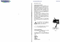
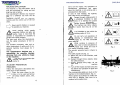
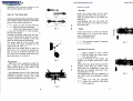
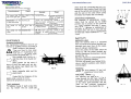
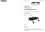
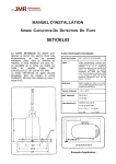
c------------------------------------------------------------------------------------------------------------------------------------------------.
f\OLOI\
officine meccaniche macchine agricole
www.molonmachinery.com
I
MOLON GIOVANNI s.n.c
di MOLON ENIO e BRUNO
VIA MESTRINA 10- ARLESEGA
35035 MESTRINO- PD- ITALY
Tel. +39-4990001 03- Fax +39-499000694
e-mail: [email protected]
USE AND MAINTENANCE MANUAL
Machine: HAY RAKE MINOR MINI 120
Model:
M002
Serial no.:
MINOR MINI 120
1 3 7 53
I
Dealer:
Delivery date:
Owner or user:
N.B: This part of the manual must be filled in at the time of delivery or installation; it is important to refer the above mentioned numbers in any communication with your dealer.
-.
INTRODUCTION
Gwde to the consultation
Congratulations on your purchase of a
MOLON machine. This machine has been
developed by engineers with years of experience on the field and it is built to the
highest MOLON quality standards. This
manual will help you to know better and
to appreciate the features of your machine and it is considered integral part of
the machine itself.
This machine can be relied on to last a
long time without inconveniences and
accidents if used in the correct way: for
this reason, it is necessary to read carefully these pages before setting up and
using the machine.
The manual, or a copy of it, must always
be on the machine to be consulted by the
user.
&
Pay attention to this symbol; it
indicates the most dangerous
operations and situations.
~This symbol points out a note or
~ a very important warning.
( E1.w•oLON. ~··'""~.-··
\i~ :i~ir;~ ~~::~·'" 20C
Machine identification
The machine is identified by the data
which are indicated in the label.
Fig. 1
The label is stuck on the frame and it is
well visible (fig. 1); it carries the following
data:
Model
Serial No
Year
Weight
R.p.m. max./1'
M
1
INDEX
WARRANTY
The warranty is valid for those parts of
the machine which present manufacturing
or assembly defects according to the
manufacturer's opinion.
The validity of the warranty covers a period of 12 months from the date of the purchase.
The warranty does not cover the parts
which are subjected to wear and tear
(teeth, plastic bearings, wheels), the
breaking caused by carriage, inexperience, carelessness, alteration and negligence and the possible injuries to people
or things caused by the use of the machine.
The warranty declines in case of a different use from the described one.
Check the machine at the time of delivery
to verify if it has been damaged during
the transport.
Possible claims for damages must be put
down in writing and sent to the dealer
within 8 (eight) days from the delivery.
The warranty declines if the instructions
given in this manual are not respected;
moreover, it declines if the machine undergoes a change or if unoriginal spare
parts are used.
The court of Padua is competent for every
controversy.
2
INTRODUCITON
page 1
Guide to the consultation
page 1
Machine identification
page 1
WARRANTY
page 2
MACHINE EMPLOYMENT
page 4
ACCIDENT PREVENTION MEASURES
page 4
USE OF THE MACHINE
page 6
Checks and advice before starting to work
page 6
The controls
page 6
Guide for the user
page 7
Adjustments for the use
page 7
Bad working and failure research
page 8
MAINTENANCE
page 8
Periodical maintenance
page 8
Teeth replacement
page 8
Extraordinary maintenance
page 9
INACITVITY
page 9
Setting for a stop
page 9
Restarting
page 9
MACHINE TRANSPORT
page 9
TECHNICAL DATA
page 10
DEMOLffiON AND GETTING RID OF MACHINE
page 10
EC DECLARATION OF CONFORMITY
page 11
3
MACHINE EMPLOYMENT
Carry out the checks, the operations of
maintenance, adjustment and repair
when the machine is not working and is
unhooked from the tractor.
In case of road haulage, the highway
code rules have to be observed.
Danger through rotating parts! It
is absolutely forbidden to take
away or to damage the guards
and to use the machine without them.
Danger through thrown objects!
The machine can throw objects
or stones that may lie on the
ground.
The machine is a hay-rake tedder. Use it
only and exclusively for raking and tedding hay and cut grass.
The manufacturer declines any responsibility for a different use from the described one.
Familiarize yourself with the operating
controls and the correct use of the machine.
&
&
~Never permit children or inexpert
~ to operate your machine.
Avoid working whilst people,
especially children and pets, are
nearby. Keep in mind that the
operator is responsible for accidents to
people and to their property.
The user must know the characteristics
and the safety procedures of the machine.
The accident prevention rules and any
other requirement of safety and of occupational medicine must always be observed.
The manufacturer declines any responsibility for possible damages
deriving from any arbitrary change
on the machine.
Do not get on the machine whilst
working, nor have yourself carried by it.
A
&
~--j
r~-~-;-----
B
It is forbidden to stay within the
Do not carry out operations of
cleaning or maintenance with
engine on, nor with connected
power take-off.
While working in presence of
dust, wear a mask and glasses to
protect your throat and eyes if
your tractor is lacking a cabin.
The acoustic pressure level is inferior to
70 dB.
The safety signals are (fig. 2):
A= Before the use of the machine, read
the manual.
B= Danger through thrown objects; keep
the safety distance.
C= Danger through drive belts; do not
take away the guards with machine
on.
D= Turn off the engine and take away the
key before any operation of repair and
maintenance.
The corresponding labels are stuck on the
machine in the indicated places. (fig. 3)
These signals must always be visible and,
when lost or illegible, they have to be
replaced with original ones.
&
&
ACCIDENT PREVENTION
MEASURES
Follow the instructions described on the
labels stuck on the machine.
Scour the area where the machine is to be used and remove
all foreign matters (stones, wire,
sticks, etc ... ).
Q
4
\i£DH1
~
c
~ working radius of 10 m.
&
&tW\1
A
D
~0
u
II'&.& ~~
::
&;;:]
i[
Fig. 2
Fig. 3
5
,!
Gwde for the user
Remember that a prudent operator is the
best security against any accident.
-Hay rake-
USE OF THE MACHINE
Checks and advice before starting to work
The machine hooks directly to the three
points of the tractor hydraulic lift.
~ Every pin must be fixed with grip
~clips to avoid the unhooking.
Fasten the supporting foot, which
is near the connection, in high position,
far from the ground.
Connect the cardan shaft when the tractor is off and the power take-off is unconnected; control the strength of the pins
which do not permit the unhooking.
The power take-off of the tractor must
not exceed the speed indicated on the
machine (R.P.M. max./ 1').
Make sure the cardan shaft is open no
less than 4 em in maximum closing position; in case of maximum extension, the
two parts of the cardan shaft must overlap no less than 15 em (fig. 4).
il
I
i
Fig. 4
~
Position the wheel levers at the same
height until the combs skim the ground.
Adjust the lateral rake to the width you
want (fig. 7).
Avoid stopping near the row when the
combs are moving; if you need to, lift up
the hydraulic lift.
-TedderPosition the wheels so that the machine
results higher (3 or 4 em) on the side of
the hay unloading (fig. 8).
Remove the lateral rake.
IW
I
¢ T h e maximum speed of advance
is 15 Km/h.
Fig. 7
Adjustments for the use
Fig. 5
The controls
- each one of the supporting wheel has
got a clamp for the height adjustment
above ground level on the right or left
side of the machine (fig. 5).
~
'
- the adjustable tie-rod of the third point
regulates the position of the comb in the
movement direction. Anyway, the comb
must be parallel to the ground (fig. 6).
¢Before starting to work, control
that the teeth are in good condition and well fixed.
In case of breaking of some teeth, you
must buy the original spare parts (code
818).
Often control the plastic bearings and the
bushings which drag the combs: these
parts, which are subjected to wear and
tear, must be replaced when their minimum thickness is 4 mm.
Their replacement, like any operation on
the V-belts, must be entrusted to skilled
workers.
¢Make sure that the protective
sheets are correctly fixed after
each operation.
d
I
Fig. 8
Fig. 6
6
7
,
Bad working and failure research
Inconvenience
Cause
The combs drag the
hay on the upper part
slow speed of the
tractor
increase the speed
Accumulation of hay
on belts and pulleys
incorrect use
unhook the machine
from the tractor and
remove the hay
The combs
rotate
do
The combs
rotate
do
not
not
the drive
broken
belt
loosened belts
Remedy
is
replacement of the belt
by skilled workers
t~ belts have to be
tightened by skilled
workers
Danger
possible accumulation
of hay on belts and
pulleys
never operate if the
machine is connected
to the tractor
never operate if the
machine is connected
to the tractor
never operate if the
machine is connected
to the tractor
133
Fig. 10
Setting for a stop
Clean the machine when it is unhooked
from the tractor and remove possible hay,
remnants and dust, then do the operations of ordinary maintenance.
Cover the points of the teeth which are
turned up with the proper accident preventive protections the machine is provided with (fig. 11).
Block the machine to avoid displacements
caused by accidental collisions.
The user will benefit from finding the machine in perfect conditions when he starts
working again.
Periodical maintenance
Any maintenance operation must be carried out by qualified workers according to
what is written in this manual.
~ When you have to carry out an
~ operation of maintenance, you
must turn off the tractor engine
and disconnect the power take-off.
Only suitable tools must be used
~ and they have to be in good con~dition.
Often grease (at least every 8
hours of work) the parts which are provided with grease cups located near the
wheel axles (fig. 9).
Fig. 9
Never grease the belts and the
Fig. 11
Restarting
Control the tyre pressure (2,5 bar) and
remove the protections from the teeth.
~plastic parts!
MACHINE TRANSPORT
Control that the thickness of the
plastic parts is superior to 4 mm.
Control the tyre pressure (2,5 bar).
The machine can easily be lifted by a
crane through two belts, type- tested for
its weight, which must be placed, the first
on the three point connection and the
other on the connection longitudinal
frame members of the wheels (fig. 12).
Teeth replacement
To replace a couple of teeth (code 818)
you must loosen the nut (code 133)
8
818
'~\1~
Extraordinary maintenance
Any operation of extraordinary maintenance must be carried out by skilled
workers and it consists on the control of
the V-belt conditions and also, if necessary, on the tightness or replacement of
the belts, on the check of wear and tear
of plastic parts with possible replacement
of these last if their thickness is inferior to
4mm.
INACTIVITY
MAINTENANCE
~
which locks the connecting tang (fig. 10).
Replace the new couple of teeth and take
care of the perfect joint between the tang
and the seat on the comb which carries
the teeth; then fasten the nut strongly.
Fig. 12
9
EC DECLARATION OF CONFORMI1Y
The points of belt placement are indicated
on the machine by proper labels (fig. 13).
For the operations of loading and unloading, the machine must be placed on a
level ground with sufficient surrounding
space.
' /~---=----' \
I
,/
f
\
\1
',, _____
~·/· /
/
MOLON GIOVANNI s.n.c.
Via Mestrina 10
35035 MESTRINO PD ITALY
Fig. 13
We declare on our exclusive responsibility that the product:
HAY RAKE
Technical data
Model
MINOR MINI
120
Combs
no.
Teeth per
comb no.
Working
width em
Maximum
width em
Length em
8
4
120
150
100
MINOR MINI 120
to which this declaration refers is in
conformity with the provisions of
2006/42/EC Directive of 17 May 2006.
Used standards: UNI EN ISO 12100; EN
953.
Person authorised to compile and draw up
the technical file:
Dr. Ing. Malon Bruno
Address:
Via Mestrina 10
35035 MESTRINO PD ITALY
DEMOLITION AND GETTING RID
OF THE MACHINE
._,
Mestrino, 29 December 2009
Proceed to demolition and getting rid of
the machine according to the regulations
in force so as to avoid ecological damages.
10
11
.'-~