1
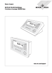
Operating instructions
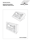
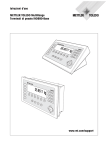
METTLER TOLEDO MultiRange
IND690-Base weighing terminals
www.mt.com/support
Congratulations on choosing the quality and precision of METTLER TOLEDO. Proper
use according to these instructions and regular calibration and maintenance by our
factory-trained service team ensure dependable and accurate operation, protecting
your investment. Contact us about a ServiceXXL agreement tailored to your needs and
budget.
We invite you to register your product at www.mt.com/productregistration so we can
contact you about enhancements, updates and important notifications concerning
your METTLER TOLEDO product.
Contents
IND690-Base
Contents
Page
1
1.1
1.2
1.3
Safety instructions .......................................................................
Safety instructions for IND690xx.....................................................
Safety instructions for IND690-24V .................................................
Safety instructions for IND690 ........................................................
2
2.1
2.2
2.3
2.4
Introduction and commissioning ................................................... 8
Documentation ............................................................................. 8
Applications ................................................................................. 9
IND690 weighing terminals ........................................................... 10
Cleaning ...................................................................................... 11
3
3.1
3.2
3.3
3.4
3.5
3.6
Basic functions ............................................................................
Switching on and off .....................................................................
Charge indicator in storage battery operation (IND690-24V only).......
Setting to zero ..............................................................................
Taring .........................................................................................
Weighing .....................................................................................
Working with several weighing platforms.........................................
12
12
12
13
13
15
15
4
4.1
4.2
4.3
4.4
4.5
4.6
4.7
4.8
4.9
4.10
4.11
4.12
4.13
4.14
4.15
4.16
4.17
Additional functions .....................................................................
Weighing with the DeltaTrac...........................................................
Dynamic weighing ........................................................................
Change weight unit .......................................................................
Working in a higher resolution .......................................................
Display gross weight.....................................................................
Specifying dynamic set points ........................................................
Multiplicative tare function .............................................................
Additive tare function .....................................................................
Sandwich tare ..............................................................................
Display ID code and test weighing platform .....................................
Identifications ...............................................................................
Recall information.........................................................................
Print or transfer data .....................................................................
Enter values with barcode or RFID reader.........................................
Working with external keypad ........................................................
Working with a second display ......................................................
Recall data from Alibi memory .......................................................
17
17
20
20
21
21
21
22
22
22
23
23
25
26
27
28
29
29
5
5.1
5.2
5.3
5.4
5.5
Settings in the master mode ........................................................
Overview of the master mode .........................................................
Operating the master mode ............................................................
TERMINAL master mode block........................................................
SCALE master mode block .............................................................
INTERFACE master mode block ......................................................
32
32
33
35
42
46
Operating instructions 22012808D 04/07
5
5
6
7
3
Contents
4
IND690-Base
6
6.1
6.2
6.3
6.4
6.5
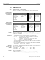
Interface description....................................................................
General .......................................................................................
MMR command set ......................................................................
METTLER TOLEDO continuous mode...............................................
METTLER TOLEDO SICS command set.............................................
Profibus DP communication with a PLC ..........................................
67
67
68
79
81
94
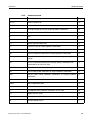
7
7.1
7.2
Application blocks ....................................................................... 102
Syntax and formats....................................................................... 102
List of the application blocks.......................................................... 105
8
What to do if …?......................................................................... 112
9
Technical data and accessories.................................................... 115
10
10.1
10.2
10.3
10.4
10.5
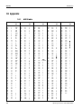
Appendix ....................................................................................
ASCII table ...................................................................................
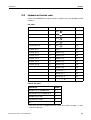
Keyboard and function codes.........................................................
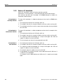
Notes on CL handshake ................................................................
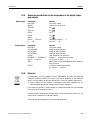
Selection possibilities for the assignment of the digital inputs
and outputs .................................................................................
Disposal......................................................................................
11
Index.......................................................................................... 120
116
116
117
118
119
119
Operating instructions 22012808D 04/07
Safety instructions
IND690-Base
1
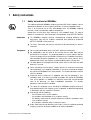
Safety instructions
1.1
Safety instructions for IND690xx
The explosion-protected IND690xx weighing terminal fulfills Device category 3 and is
approved for operation in Zone 2 (gases) and Zone 22 (dusts) hazardous areas.
There is an increased risk of injury and damage when the IND690xx weighing
terminal is used in a potentially explosive atmosphere.
Special care must be taken when working in such hazardous areas. The code of
practice is oriented to the "Safe Distribution" concept drawn up by METTLER TOLEDO.
Competence
▲ The IND690xx weighing terminal, accompanying weighing platforms and
accessories may only be installed, maintained and repaired by authorised
METTLER TOLEDO service personnel.
▲ The mains connection may only be connected or disconnected by the owner’s
electrician.
Ex approval
▲ For the exact specification please refer to the statement of conformity.
▲ No modifications may be made to the terminal and no repair work may be
performed on the modules. Any weighing platform or system modules that are
used must comply with the specifications contained in the installation instructions.
Non-compliant equipment jeopardizes the safety of the system, cancels the Ex
approval and renders any warranty or product liability claims null and void.
▲ The cable glands must be tightened so that a strain relief of ≥ 20 N per mm cable
diameter is ensured.
▲ When connecting external devices, always observe the maximum permissible
connected loads, see installation information. It must be ensured that no voltages
are fed into the IND690xx than it itself provides. The interface parameters have to
fulfill the standard.
▲ Peripheral devices without an Ex approval may only be operating in nonhazardous areas. It must be ensured that no voltages are fed into the IND690xx
than it itself provides. In addition the maximum permissible connected loads
have to be observed, see Page instalallation information. The interface
parameters have to fulfill the standard.
▲ The safety of a weighing system including the IND690xx weighing terminal is
only guaranteed when the weighing system is operated, installed and maintained
in accordance with the respective instructions.
▲ Also comply with the following:
– the instructions for the system modules
– the regulations and standards in the respective country
– the statutory requirement for electrical equipment installed in hazardous areas
in the respective country
– all instructions related to safety issued by the owner
▲ Before initial start-up and following service work, check the explosion-protected
weighing system for the proper condition of all safety-related parts.
Operating instructions 22012808D 04/07
5
Safety instructions
IND690-Base
Operation
▲ Prevent the build-up of static electricity. Therefore:
– always wear suitable working clothes when operating or performing service
work on the system,
– do not rub or wipe off the keyboard surface with a dry cloth or glove.
▲ Do not use protective hoods.
▲ Prevent damage to the weighing terminal. Hairline cracks in the keyboard
membrane are also considered damage.
▲ If the IND690xx weighing terminal, accompanying weighing platforms or
accessories are damaged:
– Switch off weighing terminal.
– Separate the weighing terminal from the mains in accordance with the
applicable regulations.
– Secure the weighing terminal against accidental start-up.
Leakages
1.2
▲ The IND690xx panel unit does not comply with any freedom-from-leaks rating.
Therefore the installer is responsible for compliance with the freedom from leaks
rating, e.g. at control cabinet installation. The respective national standards
furthermore have to be observed. At least a freedom-from-leaks rating IP54 is
required in hazardous areas.
Safety instructions for IND690-24V
▲ Never operate the IND690-24V weighing terminal in hazardous areas; there are
special scales in our product line for this purpose.
▲ The IND690-24V weighing terminal may only be connected to a power supply
(storage battery or mains) having a 24 VDC SELV power circuit in accordance
with EN 60950.
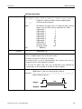
▲ Short-circuit danger!
Ensure that the power supply is connected properly:
brown lead
+24 V
blue lead
0 V or negative pole
▲ The safety of the unit is endangered if it is not operated in accordance with these
operating instructions.
▲ Only authorized personnel may open the IND690-24V weighing terminal.
6
Competence
▲ The IND690-24V weighing terminal, accompanying weighing platforms and
accessories may only be installed, maintained and repaired by authorised
METTLER TOLEDO service personnel.
Leakages
▲ The IND690-24V panel unit does not comply with any freedom-from-leaks
rating. Therefore the installer is responsible for compliance with the freedom from
leaks rating, e.g. at control cabinet installation. The respective national standards
furthermore have to be observed.
Operating instructions 22012808D 04/07
Safety instructions
IND690-Base
1.3
Safety instructions for IND690
▲ Do not operate the IND690 weighing terminal in hazardous areas. We have
special suitable scales in our range of products for hazardous areas.
▲ Ensure that the power socket outlet for the IND690 weighing terminal is earthed
and easily accessible, so that it can be de-energised rapidly in emergencies.
▲ Ensure that the supply voltage at the installation site lies within in the range of
100 V to 240 V.
▲ The safety of the device cannot be ensured if it is not operated in accordance with
these operating instructions.
▲ Only authorised personnel may open the IND690 weighing terminal.
Competence
▲ The IND690 weighing terminal, accompanying weighing platforms and
accessories may only be installed, maintained and repaired by authorised
METTLER TOLEDO service personnel.
Leakages
▲ The IND690 panel unit does not comply with any freedom-from-leaks rating.
Therefore the installer is responsible for compliance with the freedom from leaks
rating, e.g. at control cabinet installation. The respective national standards
furthermore have to be observed.
Operating instructions 22012808D 04/07
7
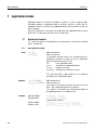
Introduction and commissioning
2
IND690-Base
Introduction and commissioning
2.1
Documentation
The weighing terminal comes supplied with a CD containing all the documentation
on the IND690 weighing system.
These installation instructions describe operation of the IND690 with the basic
software Base-690 and all possible interfaces.
If your weighing terminal is equipped with application software (Batch-690, Com690, Control-690, Count-690, Fill-690, Form-690, FormXP-690, Sum-690) you’ll
find the application specific information in the corresponding operating instructions.
8
Operating instructions 22012808D 04/07
Introduction and commissioning
IND690-Base
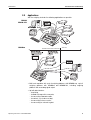
2.2
Applications
With the weighing terminals the following applications are possible:
IND690
IND690-24V
IND690xx
Hazardous area Zone 2 / Zone 22
Safe area
• Multi-scale operation with up to 4 weighing platforms with IND690 resp. up to 3
weighing platforms with IND690xx and IND690-24V, including weighing
platforms with an analog signal output.
• Up to 9 data interfaces
–
–
–
–
–
–
Operating instructions 22012808D 04/07
for printing,
for data exchange with a computer,
for connecting a barcode reader,
for control, e.g. of valves or flaps,
for connecting reference scales,
for connecting an external keypad.
9
Introduction and commissioning
2.3
2.3.1
IND690-Base
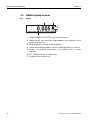
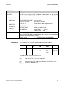
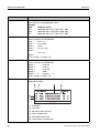
IND690 weighing terminals
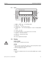
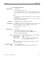
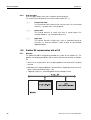
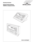
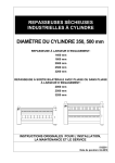
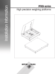
Display
1
2
3
4
5
6
7
10
1
Weight display BIG WEIGHT® with sign and decimal point
2
Stability monitor: lights up until the weighing platform has levelled out, then the
weight unit appears here
3
Range display for multi-range weighing platforms
4
Number of the weighing platform: shows the weighting platform just selected
5
Symbol * for identifying weight values in the second unit or in a higher
resolution
6
NET symbol for marking net weight values
7
Assignment of the function keys
Operating instructions 22012808D 04/07
Introduction and commissioning
IND690-Base
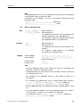
2.3.2
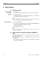
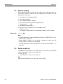
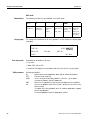
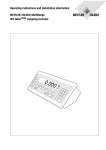
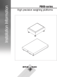
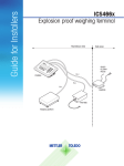
Keypad
10
1
9
2
3
4 5
6
7
8
1
CODE A ... CODE F keys – enter identification data
2
SCALE key – select scale
3
ZERO-SET key – set scale to zero, test scale
4
Function keys F1 … F6 – the current assignment is shown in the display above
the key
5
TARA key – tare scale
6
TARE SPECIFICATION key – enter known tare values numerically
7
CLEAR key – clear entries and values
8
ENTER key – accept and transfer data
9
Cursor keys
10 Numeric keypad with decimal point
2.4
Cleaning
DANGER OF SHOCK
➜ Do not open the weighing terminal to clean.
CAUTION
➜ Make sure that unused connection sockets are covered with protective caps to
protect the socket contacts from moisture and dirt.
➜ Do not use high-pressure cleaners.
Cleaning
➜ Wipe off the weighing terminal with a commercially available glass or plastic
cleaner.
Operating instructions 22012808D 04/07
11
Basic functions
3
IND690-Base
Basic functions
3.1
Switch on from the
standby mode
Switch off
Switching on and off
➜ Press any key.
The display shows a weight value based on the last tare value and zero point.
➜ Press function key OFF.
The display goes out and the IND690 weighing terminal is in the standby mode.
The zero point and tare value remain saved.
Note
If the function key OFF does not appear in the current assignment, press the cursor
key < or > several times if necessary until OFF is displayed.
Switch on with restart
1. Relieve weighing platform.
2. Press function key OFF and hold down until METTLER TOLEDO IND690 (factory
setting) or text you have specified appears in display.
Then weight value appears.
The weighing platform is restarted.
Note
The text which appears during switch-on with a restart is saved in the text
memory 20, see page 36.
3.2
Charge indicator in storage battery operation (IND690-24V
only)
If the supply voltage drops below 22.5 V, a continuous whistle sound is emitted for
approx. 10 to 30 minutes.
If the supply voltage drops below 21 V, the IND690-24V weighing terminal switches
off automatically.
➜ If the whistle sound is emitted, complete the current weighing process and charge
or replace the storage battery.
12
Operating instructions 22012808D 04/07
Basic functions
IND690-Base
3.3
Setting to zero
Setting to zero corrects the influence of minor dirt on the load plate.
In the case of excessive dirt which cannot be compensated by setting to zero, the
display shows OUT OF RANGE.
Manual zero set
1. Relieve weighing platform.
2. Press
.
The display shows 0.000 kg.
Automatic zero set
3.4
3.4.1
On certified weighing platforms the zero point of the weighing platform is automatically corrected when the weighing platform is relieved.
The automatic zero set can be switched off in the master mode on noncertified
weighing platforms.
Taring
Manual taring
1. Place empty container on scale.
2. Press T .
The tare weight is saved and the weight display set to zero.
The display shows the NET symbol.
Notes
• When the weighing platform is relieved, the saved tare weight is displayed with a
negative sign.
• The weighing platform only saves one tare value.
3.4.2
Automatic taring
Condition
AUTOTARA ON must be set in the master mode, see page 43.
➜ Place empty container on scale.
The container weight is automatically saved and the weight display set to zero.
The display shows the NET symbol.
Note
The saved tare weight is automatically deleted with the load is removed from the
weighing platform.
Operating instructions 22012808D 04/07
13
Basic functions
IND690-Base
3.4.3
Enter numerically
Specify tare weight
1. Press
PT
.
2. Enter tare weight (container weight) and confirm with 8 .
When weighing platform is relieved, the entered tare weight is displayed with a
negative sign.
Note
The weight unit for entering the tare weight can be selected with the cursor keys
< or >.
Correct entry
Copy tare
constant
➜ Clear the entry character by character with
and repeat correctly.
The IND690 has 999 tare memories for frequently used tare weights programmed in
the master mode.
1. Enter memory number: 1… 999.
2. Press PT .
The memory number, the saved tare weight and the designation appear briefly in
the display. The next to appear is the weight display with the net weight referred
to the called-up tare weight and the symbol NET.
3.4.4
Recall currently saved tare weight
The saved tare weight can be recalled at any time.
➜ Enter INFO, PT sequence.
The saved tare weight is displayed.
3.4.5
Clear tare weight
➜ Relieve weighing platform and tare.
– or –
➜ Specify tare weight 0.
– or –
➜ Enter
PT
,
sequence.
Note
If AUTO CLEAR TARE ON is selected in the master mode, the saved tare weight is
automatically deleted with the load is removed from the weighing platform.
14
Operating instructions 22012808D 04/07
Basic functions
IND690-Base
3.5
Weighing without taring
Weighing with taring
Weighing
➜ Lay weighing sample on weighing platform.
Gross weight (total weight) is displayed.
1. Place the empty container on the weighing platform and tare.
2. Pour in weighing sample.
The display shows the net weight and the NET symbol.
Weighing with tare
specification
1. Place filled container on weighing platform.
The display shows the gross weight (total weight).
2. Specify tare weight or recall tare memory.
The display shows the net weight (container content) and the NET symbol.
Note
If the MinWeight function is activated in the master mode, weight values that fall
below the defined minimum weight are identified with the symbol
3.6
.
Working with several weighing platforms
Up to 4 weighing platforms can be connected to the IND690, and up to 3 weighing
platforms can be connected to the IND690xx and IND690-24V.
Depending on the setting in master mode, only the currently active scale appears in
the display (serial Multi-scale mode) or all scales are operated at the same time
(parallel multi-scale mode). A constantly updated sum scale is also available in
parallel multi-scale mode.
3.6.1
Switch over weighing platform
The weighing platform currently selected is shown on the terminal.
➜ Press
.
The next weighing platform is selected.
– or –
➜ Enter number of weighing platform and press
The desired weighing platform is selected.
Operating instructions 22012808D 04/07
.
15
Basic functions
IND690-Base
3.6.2
Displaying several scales simultaneously
Condition
PARALLEL SCALE is selected in the master mode.
➜ Press the cursor key < or > as often as necessary until all scales are shown in
the display.
Notes
• When all scales are displayed, only the function keys UNIT and GROSS are still
active. These function keys then act on all connected scales.
• The sum scale can only be operated non-verifiably. It is therefore identified by the
symbol Σ.
16
Operating instructions 22012808D 04/07
Additional functions
IND690-Base
4
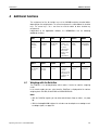
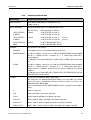
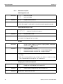
Additional functions
The assignment of the 6 function keys of the IND690 weighing terminal differs
depending on the weighing task. The current assignment is shown above the function
keys. The cursor keys < or > can then be used to switch to other function key
assignments.
Independent of the application software, the IND690-Base has the following
additional functions:
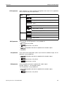
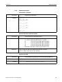
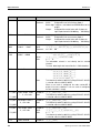
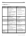
4.1
DELT
DYN
UNIT
X 10
GROSS
MODE
Weighing
with the
DeltaTrac,
see 4.1
Dynamic
weighing,
see 4.2
Change
weight unit,
see 4.3
Increase resolution, see
4.4. This key
is not assigned when
the control
mode is continually
switched on.
Display gross
weight,
see 4.5
Activate
master mode,
see Chapter 5
MUL-T
ADD-T
ITARE
SETP
OFF
INFO
Multiplicative
tare function,
see 4.7
Additive tare
function,
see 4.8
Sandwich tare,
see 4.9
Set dynamic
set points,
see 4.6.
This key is not
assigned if no
set points are
defined.
Switching off
terminal
Calling up
information
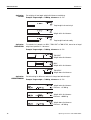
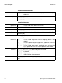
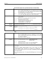
Weighing with the DeltaTrac
The DeltaTrac is an analog display which makes it easier to read the weighing
results.
In the master mode you can select how the DeltaTrac is displayed for the various
weighing tasks FILLING, CLASSIFYING or CHECKWEIGHING.
Notes
• With the DeltaTrac signals you can also control lamps, flaps or valves, see page
56.
• With the AnalogOut-690 interface the net value can be output as an analog current
or voltage signal, see page 59.
Operating instructions 22012808D 04/07
17
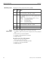
Additional functions
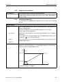
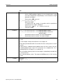
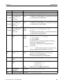
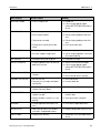
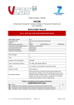
Application
FILLING
IND690-Base
For weighing-in to a target weight with tolerance monitoring.
Example: Target weight = 1.000 kg, tolerance = +/–1 %
Target weight not reached yet
Weight within the tolerance
Target weight reached exactly
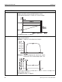
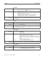
Application
CLASSIFYING
To evaluate test samples as OKAY, TOO LIGHT or TOO HEAVY, based on a target
weight and specified +/– tolerances.
Example: Target weight = 1.000 kg, tolerance = +/–1 %
TOO LIGHT
Weight below the tolerance
OKAY
Weight within the tolerance
TOO HEAVY
Weight above the tolerance
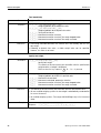
Application
CHECKWEIGHING
For determining the difference between the target and actual weight.
Example: Target weight = 1.000 kg, tolerance = +/–1 %
Weight below the tolerance
Difference: –0.100 kg
Weight within the tolerance
Difference: +0.002 kg
Weight above the tolerance
Difference: +0.100 kg
18
Operating instructions 22012808D 04/07
Additional functions
IND690-Base
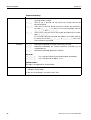
4.1.1
Enter numerically
Preset DeltaTrac target values
1. Press DELT key.
2. Enter target weight and confirm with 8 .
3. Enter the lower tolerance TOL (–) as a % of the target weight and confirm with 8 .
4. Enter the upper tolerance TOL (+) as a % of the target weight and confirm with
8.
Notes
• The weight unit for entering the DeltaTrac target values can be selected with the
cursor keys < or >.
• The terminal suggests symmetrical tolerances TOL. (+) and TOL. (–). However,
different tolerances are also permissible.
Correct entry
Copy constants
➜ With
the entry is corrected character by character.
The IND690 weighing terminal has 999 DeltaTrac memories for frequently used
target values and tolerances, which are programmed in the master mode.
1. Enter number of DeltaTrac memory: 1 … 999.
2. Press DELT key.
Reference sample
1. Press DELT key.
2. Lay sample on weighing platform and confirm with
.
3. Only for FILLING and CLASSIFYING: Enter tolerance and confirm with 8 .
4. Remove sample from weighing platform.
Limits
Minimum target value
Maximum target value
Minimum tolerance
Maximum tolerance
10 Digit, can be adjusted in master mode, see page 37
configured maximum load
1 Digit
10 % for the applications FILLING, CHECKWEIGHING
50 % for the application CLASSIFYING
Note
If the limits are not observed, a message appears in the display, e.g. MIN-DEL = ...,
for too small a target value.
Clear DeltaTrac target
value
➜ Press DELT
key sequence.
DELTA CLEARED appears briefly in the display, then the weight is shown.
Operating instructions 22012808D 04/07
19
Additional functions
IND690-Base
4.2
Dynamic weighing
With the dynamic weighing function you can weigh restless weighing samples, e.g.
live animals. To do this, specify the number of weighing cycles for which the mean
weight value is to be taken.
1. Set container on the weighing platform.
2. Tare weighing platform.
3. Place weighing sample in container.
4. Press DYN key and enter number of weighing cycles.
Possible values: 1 … 255.
5. Start dynamic weighing with 8 .
6. After cycle time has expired, center line of display shows:
RESULT x.xxxx kg.
This display is retained until the next weighing is started or until it is cleared.
Delete result
➜ Press
.
Notes
• Dynamic weighing results are automatically printed when AUTO PRINT is set in the
master mode, see page 40.
• During dynamic weighing it is not possible to display the weight value BIG
WEIGHT DISPLAY, which fills the entire display.
• Dynamic weighing can also be started with the interface command AW016..., see
page 106.
4.3
Change weight unit
If an additional, second weight unit is configured in the master mode, it is possible to
switch back and forth between the two weight units.
➜ Press UNIT key.
The weight value is shown in the second unit.
Note
Possible second weight units are: mg, g, kg, lb, oz, ozt, dwt.
20
Operating instructions 22012808D 04/07
Additional functions
IND690-Base
4.4
Working in a higher resolution
Depending on the setting of the master mode block CONTROL MODE (see page 40),
the weight value can be displayed in a higher resolution continuously or when called.
Weight values in a higher resolution are marked with a *.
Displaying weight values in higher resolution
➜ Press X 10 key.
The weight value is displayed in at least a 10x higher resolution.
The higher resolution is displayed until the X 10 key is pressed again.
Note
With certified weighing platforms, the weight value only appears in a higher
resolution as long as the X 10 key is pressed.
4.5
Display gross weight
The gross weight can only be displayed when a tare weight has been saved.
➜ Press GROSS key and hold down.
The gross weight is displayed.
4.6
Specifying dynamic set points
Conditions
• 4 I/O-690 interface or 8-690 relay box connected.
• SETPOINT MODE ON is selected and a dynamic switching point is allocated to at
least one output in the mastermode.
Use
If the specified set point values are exceeded or dropped below, digital outputs are
set, e.g. for controlling lamps, flaps, valves etc.
Dynamic set points can be set for each weighing procedure individually.
The set points are retained until they are overwritten with a new value or deleted.
Specifying set points
1. Press the SETP key; the entry prompt for the first dynamic set point appears.
2. Enter the desired weight value and confirm with 8 .
3. If additional dynamic set points are configured, the entry prompt appears for the
next dynamic set point.
4. Enter the desired weight value and confirm with 8 .
5. Repeat the procedure until all set points have been entered.
Deleting set points
➜ Press the SETP key and delete the value with the
Operating instructions 22012808D 04/07
.
21
Additional functions
IND690-Base
4.7
Multiplicative tare function
The multiplicative tare function is particularly suitable when pallets with identical
containers are filled. If the number of containers and tare of the individual container
are known, the weighing terminal calculates the total tare.
1. Press MUL-T key.
2. Enter known tare weight of individual container and confirm with 8 .
3. Enter number of containers and confirm with 8 .
When the weighing platform is relieved, the total tare value is shown in the
display with a negative sign.
Note
The weight unit for entering the tare weight can be selected with the cursor keys
< and >.
4.8
Additive tare function
With the additive tare function you can subtract the tare of additional containers with
a know tare weight for related weighings, e.g. if containers with different weights are
filled on one pallet.
1. Place container on scale and press ADD-T key.
2. Enter known tare weight and confirm with 8 .
The total net weight appears in the weight display.
Note
The weight unit for entering the tare weight can be selected with the cursor keys
< or >.
4.9
Sandwich tare
With the sandwich tare function you can detect additional tare weights for related
weighings without loosing the total gross and total net.
Example
In production or shipping boxes are laid between individual layers in the transport
container. The weight of these boxes can be subtracted with this function.
1. Press ITARE key.
2. Place sandwich tare, e.g. box, on scale and confirm with 8 .
The net weight is retained.
22
Operating instructions 22012808D 04/07
Additional functions
IND690-Base
4.10
Display ID code and test weighing platform
Each time the weighing platform configuration is changed the ID code counter is
increased by 1. On certified weighing platforms the displayed ID code must match
the ID code on the ID code sticker, otherwise the calibration is no longer valid.
Display ID code
➜ Press
and hold until IDENTCODE = ... appears in the display.
Test weighing platform
➜ Press
again.
The connected weighing platform is checked. The display shows CHECK SCALE
and then SCALE IS OK after completing the test.
Note
If weighing platform is defective, display shows SCALE ERROR.
4.11
Identifications
The weighing terminal is equipped with 6 identification data memories for storing
identification data Code A … Code F.
The memories have a name, e.g. Article No., and a content which identifies the
current weighing, e.g. 1234567.
The memories are named in the master mode, and the names can be noted on the
keyboard. When the CODE keys are pressed, the name appears in the display.
Identification data Code A … Code F can be entered or recalled for each weighing
and are printed immediately.
4.11.1
Enter
numerical identification
Enter identification
An identification may contain a maximum of 30 characters.
1. Press one of the keys CODE A … CODE F.
2. Enter identification data Code A … Code F via the numeric keypad and confirm
with 8 .
Operating instructions 22012808D 04/07
23
Additional functions
IND690-Base
Enter
alphanumeric
identification
1. Press one of the keys CODE A … CODE F.
The functions keys are given the following assignment:
ABCDE
FGHIJ
KLMNO
PQRST
UVWXY
Z/-()
Selection of
letters A to E
Selection of
letters F to J
Selection of
letters K to O
Selection of
letters P to T
Selection of
letters U to Y
Selection of
letter Z or a
special
character
2. Select desired group of letters, e.g. press KLMNO key.
3. Select desired letter.
The display changes again to the above selection.
4. Repeat entry in steps 2 and 3 for additional characters.
Notes
• Letters and numbers can be combined as desired.
• It is possible to switch between upper case and lower case with the cursor keys
and . The following special characters are then also available with the lower
case letters: *, $, %, &.
Recall fixed text
memory
The IND690 weighing terminal is equipped with 999 memories for fixed texts which
can be programmed in the master mode and used as identifications.
1. Enter memory number: 1 ... 999.
2. Press a key CODE A … CODE F.
The saved fixed text is now assigned to the selected identification Code A …
Code F.
Other entry possibilities
4.11.2
Identifications can also be entered with a barcode or RFID reader, see section 4.14,
or with an external keypad, see section 4.15.
Clear identifications
➜ Press desired key CODE A … CODE F and clear memory content with
24
.
Operating instructions 22012808D 04/07
Additional functions
IND690-Base
4.12
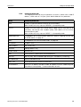
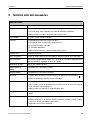
Recall information
On the weighing terminal memory contents and system information can be recalled.
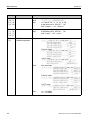
1. Press INFO key.
Then the following function key assignment appears:
DELT
TARE
TEXT
ALIBI
DATE
VERS
Display
DeltaTrac
values
Display tare
weight
Display fixed
texts and
name of keys
CODE A …
CODE F
Recall content
of alibi
memory, see
section 4.17.
This selection
only appears
when AlibiMemory-690
is installed.
Display date
and time
Display
version
numbers of
installed
software
modules
W&M
ERROR
COM
Display
checksum of
the software
relevant to
calibration.
The correct
checksum is
documented
in the calibration approval.
Fault /
Event memory
display
Calling up the
settings of the
interfaces
2. Select desired information.
The information is displayed for the set DISPLAY DURATION, then the weighing
terminal changes to the weighing mode again.
Notes
• When several values are displayed, the IND690-Base automatically changes to
the next value after the set DISPLAY DURATION.
• With
it is possible to switch to the next value or back to the weighing mode.
• When the GA46 printer is connected, the version numbers of the installed software
modules are automatically printed.
• After COM has been pressed, the settings of all 9 interfaces are displayed
consecutively, for example
COM1: RS232
MODE: DEFAULT
SETTING: 6900, N, 8, 1
STATUS: ACTIVE
Operating instructions 22012808D 04/07
25
Additional functions
IND690-Base
4.12.1
Recall memory
1. Press INFO key.
2. Enter number of memory and press DELT, TARA or TEXT key depending on
desired memory.
Recall name of CODE A … CODE F keys
1. Press INFO key.
2. Press one of the keys CODE A … CODE F.
The display shows the current Code.
4.12.2
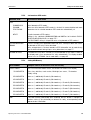
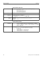
Calling up information on the installed interface modules
Information on the installed interface modules can be called up with the following key
combinations:
INFO 50
Type and software version of the installed WLAN module
INFO 51
Status of the WLAN module
INFO 60
Type and software version of the installed Bluetooth module
INFO 61
Status of the Bluetooth module
4.12.3
Recall application-specific information
See operating instructions of the relevant application software.
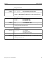
4.13
Print or transfer data
If a printer or computer is connected, weighing results can be printed out or
transferred to the computer.
In the master mode you can set the following for this purpose:
• Data to be printed or transferred,
• Manual or automatic data transfer,
• Key which triggers printing or data transfer.
Factory setting
• Manual triggering with 8 .
• The content of the display is transferred or printed.
26
Operating instructions 22012808D 04/07
Additional functions
IND690-Base
4.14
Enter values with barcode or RFID reader
If you have connected a barcode or RFID reader to the weighing terminal, you can
make all required entries, such as identifications or target specifications, easily with
the barcode or RFID reader.
4.14.1
Example
Read in any desired entries with the barcode or RFID reader
Read in identification Code A
1. Press CODE A key; the weighing terminal expects the entry of Code A.
2. Enter identification Code A with the barcode or RFID reader.
The identification read in appears in the display.
3. Confirm barcode entry with 8 .
4.14.2
Example
Read in a frequently used entry directly with the barcode or RFID reader
If your working procedure repeatedly requires the same entry, you can configure the
barcode or RFID reader in the master mode (see page 55) so that no additional keys
need to be pressed on the weighing terminal.
Barcodes are automatically read in as Code A
If the working procedure requires the entry of Code A:
➜ Enter identification Code A with barcode reader.
The information read in appears in the display and is automatically processed by
the weighing terminal as Code A.
Operating instructions 22012808D 04/07
27
Additional functions
IND690-Base
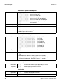
4.15
Working with external keypad
If the weighing terminal is equipped with the interface PS2-690, an external keyboard
can be connected so that alphanumerical values can be entered conveniently.
In addition to the alpha and numerical keys, the following additional scale functions
can also be operated with the external AK-MFII keypad.
Function for IND690-Base
External
keypad
Function for IND690-Base
External
keypad
Function key F1
F1
CODE A key
Shift F1
Function key F2
F2
CODE B key
Shift F2
Function key F3
F3
CODE C key
Shift F3
Function key F4
F4
CODE D key
Shift F4
Function key F5
F5
CODE E key
Shift F5
Function key F6
F6
CODE F key
Shift F6
key
F9
key
Shift F9
key
F10
key
Shift F10
T
key
F11
T
key
Shift F11
PT
key
F12
PT
key
Shift F12
Note
The language of your external keyboard can be set in the master mode block LAYOUT
EXT. KEYBOARD, see page 59.
28
Operating instructions 22012808D 04/07
Additional functions
IND690-Base
4.16
Working with a second display
An ID1 Plus, ID3s, ID7 or another IND690 weighing terminal can be connected to the
IND690 weighing terminal as a second display.
Conditions
• Interface CL 20mA-690 installed in passive operating mode (factory setting).
• AUTO-DIR setting selected in master mode (see page 49).
• Weighing terminal is connected as second display with cable 00 504 511.
Operation possibilities on second display
The following functions are also possible on the second display:
• Set to zero
• Taring
IND690 as second display
With IND690 as a second display, the weight value fills the entire display (BIG
WEIGHT DISPLAY ON).
4.17
Recall data from Alibi memory
With the AlibiMemory-690 memory module you can fulfill your recording obligations
in certified operation without having to archive paper.
AlibiMemory-690 automatically assigns every weighing operation a consecutive data
record number that also appears on the printout, saves the net and tare value, the
date and the time and also the scale number, tare source, MinWeigh and, if
necessary, additional ID codes.
Immediately after the following actions, entries are made in the alibi memory:
• Interface commands "S" and "SX"
• Interface command "SR" as soon as a stable weight value has been determined
• Pressing 8
• Automatic transfer key printout when a certain weight value is reached (AutoPrint)
The AlibiMemory-690 operates according to the principle of a ring memory: When
the capacity limit of 675500 data records is reached, the oldest data record is
deleted and overwritten with data from the latest weighing.
By entering suitable search criteria you can quickly access the data of a very specific
weighing.
Operating instructions 22012808D 04/07
29
Additional functions
IND690-Base
4.17.1
Initiate
➜ Press INFO, ALIBI key sequence.
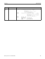
The function keys change to the following assignment:
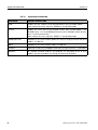
4.17.2
FIND
>>...
PRINT
-> Num
END
Enter search
criteria
Search for
next
matching
data record
starting with
oldest
Print
displayed
data record
Search for
data record
with known
data record
number
Exit Info Alibi
and return to
normal mode
Fast search with entry of data record number
1. Press ->Num key.
2. Enter number of data record to be searched for and confirm with 8 .
AlibiMemory-690 now searches for the desired data record.
Notes
• The search may take up to 10 seconds.
• If no data record with the entered number is found, the message NO MATCHING
DATA RECORD appears.
4.17.3
Search with other search criteria
➜ Press FIND key.
The function keys are given the following assignment:
DATE
TIME
NET
TARE
START
END
Enter
date as
search
criterion
Enter
time as
search
criterion
Enter net
value as
search
criterion
Enter
tare value as
search
criterion
Start search
with entered
search
criteria
Terminate
search
All offered search criteria can be combined with each other.
The entered search criteria are shown in the display in clear text.
This enables you to search for a find a specific weighing.
Enter date
➜ Press DATE key and enter complete date in DD.MM.YY form.
Enter time
➜ Press TIME key and enter desired time in one of following formats.
Format HH
all weighings between HH.00.00 and HH.59.59 are found
Format HH.MM
all weighings between HH.MM.00 and HH.MM.59 are found
Format HH.MM.SS only the weighing at the time HH.MM.SS is found
30
Operating instructions 22012808D 04/07
Additional functions
IND690-Base
Enter net/tare value
1. Press NET or TARE key.
2. Enter weight value and confirm with 8 .
The function key assignment changes back again for selection of the search
criteria.
Note
The weight unit for entering the weight values can be selected with the cursor keys
< or >.
Start search
➜ Press START key.
AlibiMemory-690 searches for the oldest data record which meets the entered
search criteria.
Notes
• The search may take up to 10 seconds.
• If no data record with the entered values is found, the message NO MATCHING
DATE RECORD appears.
• If no search criterion has been entered, the oldest data record is displayed.
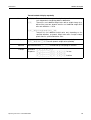
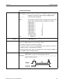
4.17.4
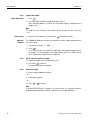
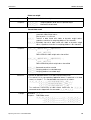
Example 1st page
Displaying data records
Found data records are shown in the display on 2 pages. You can change between
the two pages with the cursor keys < or >.
D/Z:
NUM:
NET:
TARE:
02.04.98
000987
25.000 KG
100,346 KG
09.25.51
1/2
1
PT
Example 2nd page
ARTICLE NO.
A: 123456789
ORDER NO.
B: 55555
2/2
Scroll forward/back
The key >>... enables you to scroll within the found data records.
Notes
• When, during scrolling with the key >>... all entries of the AlibiMemory-690 have
been searched through, the message END OF FILE appears.
• If a weight value has fallen below the set minimum weight, the weight value is
also shown in the alibi memory with the symbol
Operating instructions 22012808D 04/07
.
31
Settings in the master mode
5
IND690-Base
Settings in the master mode
5.1
Overview of the master mode
In the master mode you adapt the IND690-Base weighing terminal to meet your
needs. Depending on the configuration, the master mode is divided into 4 or 5
master mode blocks, which are in turn divided into further blocks.
32
TERMINAL
For system settings, such as entering the date and time or loading permanent texts,
see section 5.3.
PAC
To set application-specific parameters, see operating instructions of the respective
application software.
This block does not appear with IND690-Base.
SCALE
To select one of the connected weighing platforms. For each selected weighing
platform the parameters are then set which concern the weight value, e.g. stability
detector, unit, etc., see section 5.4.
INTERFACES
To select an interface. The communication parameters are then set for each interface,
see section 5.5.
SERVICE
For configuring the weighing platform(s).
On IDNet weighing platforms only for METTLER TOLEDO service technicians.
On weighing platforms with an analog signal output, see service manual A/D
converter Point ME-22004256.
Operating instructions 22012808D 04/07
Settings in the master mode
IND690-Base
5.2
5.2.1
Operating the master mode
Enter the master mode
1. Press MODE key.
If the current function keys assignment does not contain MODE, press the cursor
keys < or > as often as necessary until the MODE key appears.
2. Enter personal code if configured.
The display shows the first master mode block TERMINAL.
5.2.2
Assignment of function keys in the master mode
Assignment on the top level
On the top level of the master mode the function keys are assigned as follows:
←
→
↑
END
OK
Change to
previous block
within a level
Change to next
block within a
level
Exit level and
return to
higher-level
block
Exit the master
mode and
return to
normal mode
Recall lowerlevel block or
confirm
selection
➜ Select the function by pressing the function key.
Example
➜ Press the END key to exit the master mode and return to the normal mode.
When the function keys are otherwise allocated
➜ Press the cursor keys < or > repeatedly until the function key assignment shown
above appears.
Assignment in input masks
In input masks for several parameters, the function keys are assigned as follows:
E
<
Select
parameters
Setting parameters
Operating instructions 22012808D 04/07
>
Fu
EDIT
↑
Select function
of function key
F5:
EDIT, STD,
ADD, INS, etc.
Possible
assignments:
ADD
INS
EDIT
DEL
PRINT
STD
EDIT
GOTO
Accept
settings and
return to
higher-level
block
33
Settings in the master mode
IND690-Base
5.2.3
Master mode operation with the navigation keys
Instead of the function keys, it is also possible to use the navigation keys to operate
the master mode.
Function key
Navigation key
F1 (←)
<
F2 (→)
>
F4 (↑)
T
F6 (OK)
8
5.2.4
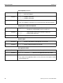
Orientation in the master mode
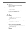
For improved orientation the display shows the last steps in the path of the current
master mode block.
Example
The upper 3 lines of the display show the following path for selecting the DeltaTrac
application FILLING:
5.2.5
Entries in the master mode
The following basic rules apply to entries made in the master mode:
• Confirm (alpha)numeric entries with 8 .
• Alphanumeric entries with the IND690: see page 24.
• To accept the displayed value: Press 8 .
5.2.6
Emergency entrance into the master mode
If a personal code has been assigned for entering the master mode and you have
forgotten your code, you can still enter the master mode:
➜ Enter the character sequence C, L, E, A, R as your personal code.
34
Operating instructions 22012808D 04/07
Settings in the master mode
IND690-Base
5.3
5.3.1
Legend
TERMINAL master mode block
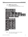
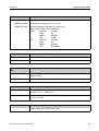
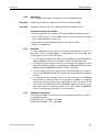
Overview of the TERMINAL master mode block
In the TERMINAL master mode block you enter the following system settings:
• Blocks highlighted in grey are described in detail in the following.
• Factory settings are printed in bold print.
Operating instructions 22012808D 04/07
35
Settings in the master mode
5.3.2
IND690-Base
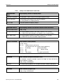
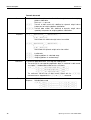
Settings in the master mode block TERMINAL
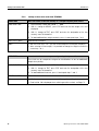
FIXED TARE
Store tare values in the tare memory as a safeguard against power failure
LOAD FIXED TARE
1. Select memory number with GOTO: 1 ... 999.
2. With E, change to WEIGHT, press EDIT and enter the tare weight in the unit
displayed.
3. With E, change to TEXT, press EDIT and enter the designation of the tare
memory, max. 30 characters.
4. To load additional tare weight constants, press E and repeat steps 1 to 3.
DELETE ALL TARES
Delete all tare memories.
Notes
• With the cursor keys < or > you can scroll through the existing tare memories.
• When entering the tare weight, it is possible to change the weight unit with the
cursor keys < or >.
FIXED TEXT
Store texts in the text memory as a safeguard against power failure
These texts can for example be assigned as identifications or can be additionally
output when printing.
LOAD FIXED TEXTS
1. Select memory number with GOTO: 1 ... 999.
2. With E, change to TEXT, press EDIT and enter the designation of the text
memory, max. 30 characters.
3. To load additional fixed texts, press E and repeat steps 1 and 2.
DELETE ALL TEXTS
Delete all text memories.
Notes
• With the cursor keys < or > you can scroll through the existing text memories.
• Fixed text No. 20 is displayed when switching on with a restart, see Page 12.
36
Operating instructions 22012808D 04/07
Settings in the master mode
IND690-Base
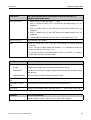
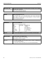
FIXED DELTA
Store target weight/tolerance combinations in DeltaTrac memories as a
safeguard against power failure
LOAD FIXED DELTA
1. Select memory number with GOTO: 1 ... 999.
2. With E, change to TARGET, press EDIT and enter the target weight in the unit
displayed.
3. With E, change to TOL.(–), press EDIT and enter the lower tolerance in the unit
displayed.
4. With E, change to TOL.(+), press EDIT and enter the upper tolerance in the unit
displayed.
5. To load additional DeltaTrac constants, press E and repeat steps 1 to 4.
DELETE ALL DELTA
Delete all DeltaTrac memories.
Notes
• With the cursor keys < or > you can scroll through the existing DeltaTrac
memories.
• When entering the target weight and tolerances, it is possible to change the
weight unit with the cursor keys < or >.
• The terminal suggests symmetrical tolerances TOL. (+) and TOL. (–). However,
different tolerances are also permissible.
DELTATRAC
Set DeltaTrac application
TYPE
Select DeltaTrac application
FILLING
Weigh in target weight within a tolerance range (factory setting)
CLASSIFYING
Evaluate the test samples as good, too light or too heavy based on the target weight
and tolerance
CHECKWEIGHING
Determine difference between target and actual weight
AUTO PRINT WITHIN
TOL
Automatic printout when actual weight lies within the specified tolerance
PRINT ONLY WITHIN
TOL
Printout only when actual value lies within the specified tolerance
MIN. DELTA
Specify minimum target weight, adjustable from 10 ... 100 d, factory setting: 40 d
LANGUAGE
Select dialog language
Possible settings: German, English, French, Dutch, Italian, Spanish
Operating instructions 22012808D 04/07
37
Settings in the master mode
IND690-Base
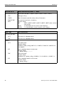
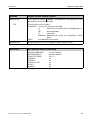
KEYS A B C D E F
Name identification keys CODE A … CODE F
KEY A (B, C, D, E, F)
Identification data CODE A (CODE B, CODE C, CODE D, CODE E, CODE F)
TEXT
Naming the ID key
LENGTH
Max. 30 characters possible, factory setting: 20 characters
REQUEST FOR
INPUT
Set request for input for the selected key
Possible settings:
OFF
CODE A (CODE B, CODE C, CODE D, CODE E, CODE F) does not have
to be entered
REUSE
An identification can be used for several weighings
RENEW
A new identification must be entered for every weighing
DATE / TIME
Enter date and time
SET DATE AND TIME
DATE
Enter date in the displayed format
TIME
Enter time in the displayed format
FORMAT
38
DATE
Select date format
Possible settings:
DD.MM.YY (factory setting), MM.DD.YY, YY.MM.DD, DD.MM.YYYY, MM.DD.YYYY,
YYYY.MM.DD
SEP
Select separating character in date format
Possible settings:
"." (factory setting), ":", "/", "–"
TIME
Select time format
Possible settings:
HH:MM:SS 24 h (factory setting), HH:MM:SS 12 h, HH:MM 24 h, HH:MM 12 h
SEP
Select separating character in time format
Possible settings:
":" (factory setting), “.“
Operating instructions 22012808D 04/07
Settings in the master mode
IND690-Base
DATE / TIME
Enter date and time
SUMMER TIME
SUMMER TIME OFF
No automatic changeover to summer time
SUMMER TIME ON
Configure automatic changeover to summer time
Other settings, factory settings in brackets:
START
WEEKDAY
(Sunday)
WEEK
(4)
MONTH
(MARCH)
TIME
(2:00)
END
WEEKDAY
(Sunday)
WEEK
(4)
MONTH
(October)
TIME
(03:00:00)
PERSONAL CODE
Load or delete code for entering the master mode
CODE
Enter code with a maximum of 8 alphanumeric characters.
Comment
If no code is entered, access to the master mode is unrestricted.
MASTER MODE START
POS.
Select start position for entering the master mode
NORMAL
Selection of the master mode blocks always begins with the TERMINAL block
(factory setting).
LAST POSITION
When entering the master mode, the last block edited is displayed immediately.
SCREEN SAVER
Switch screen saver on or off
WAITING TIME
Enter time until screen saver is activated.
Possible values: 1 ... 60 minutes
Comment
To hold all display elements at the same luminosity, we recommend not switching
off the screen saver.
BIG WEIGHT DISPLAY
Switch full-display indication of the weight on or off
Factory setting: BIG WEIGHT DISPLAY ON
Operating instructions 22012808D 04/07
39
Settings in the master mode
IND690-Base
CONTROL MODE
Adjust control mode
X10 KEY
Activation of control mode with X10 key (factory setting).
CONTROL MODE ON
This setting is only possible with non-certified scales.
The weighing terminal always operates with the higher resolution.
DYNAMIC WEIGHING
Set printing during dynamic weighing
NO PRINT
Results during dynamic weighing are not automatically printed out (factory setting).
AUTO PRINT
Each result during dynamic weighing is automatically printed.
Dynamic weights are marked with "Result:" on the printout.
ID5 MODE
Deactivating or activating downward compatibility with ID5
If ID5 MODE ON is selected, the IND690 is operated with downward compatibility to
the ID5.
Affected settings
Text length of identification data
Text length for keys CODE A ... D
Date/time
Barcode print command
18 characters
max. 18 characters
dd/mm/yy, hh-mm-ss
P$#1EAN13
P$#2Code 39
P$#3EAN13
Factory setting: ID5 MODE OFF
DISPLAY DURATION
Set display duration for messages
ERROR MESSAGES
Set display duration for error messages; factory setting: 2 seconds
INFO MESSAGES
Set display duration for informational messages; factory setting: 3 seconds
40
Operating instructions 22012808D 04/07
Settings in the master mode
IND690-Base
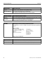
MODE SCALES
Select between serial and parallel operating mode for the connected scales
SCALES SERIAL
Serial operation of the connected scales: Only the weight value of the current scale
is displayed.
SCALES PARALLEL
Parallel operation of the connected scales: All weight values of the connected scales
are displayed simultaneously.
SUM SCALE
A sum scale can be defined in parallel scale operation.
1. SUM SCALE: Select ACTIVATED.
2. With E, change to SCALE 1 and select YES with < or > if this scale is to be the
sum scale.
3. Repeat the procedure for SCALE 2 - SCALE 4.
Factory setting: SUM SCALE DEACTIVATED
ACOUSTIC SIGNAL
Signal tone On/Off
Factory setting: SIGNAL ON
RESET TERMINAL
Reset all terminal functions to the factory setting
DELTATRAC
DATE/TIME
MASTER MODE START POS.
SCREENSAVER
BIG WEIGHT DISPLAY
DYNAMIC WEIGHING
CONTROL MODE
ID5 MODE
DISPLAY DURATION
MODE SCALES
ACOUSTIC SIGNAL
Comment
Filling
Autoprint within tol: no
Print only within tol: no
Min.Delta = 40 d
Format = DD.MM.YY / HH:MM:SS 24h
Summertime: off
Normal
off
On
No printout
X 10 key
Off
2 / 3 seconds
Serial
on
The memories are not affected by this.
Operating instructions 22012808D 04/07
41
Settings in the master mode
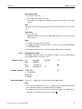
5.4
IND690-Base
SCALE master mode block
In the first block the weighing platform is selected: SCALE 1 … SCALE 4 with IND690
and SCALE 1 … SCALE 3 with IND690xx or IND690-24V.
The settings for the METTLER TOLEDO industrial scales are described below. The
settings for METTLER TOLEDO LabTec Excellence scales are described in the
corresponding operating instructions.
5.4.1
Legend
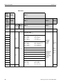
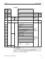
Overview of the SCALE master mode block
In the SCALE master mode block the following settings for the weight can be carried
out:
• Blocks highlighted in grey are described in detail in the following.
• Factory settings are printed in bold print.
• Blocks which only appear under certain conditions have a dotted outline.
42
Operating instructions 22012808D 04/07
Settings in the master mode
IND690-Base
5.4.2
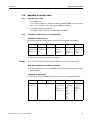
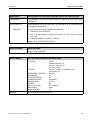
Settings in the SCALE master mode block
WEIGHING-PROC
ADAPT
Adapt weighing platform to weighing sample
UNIVERSAL WEIGHING
For solid bodies, coarse filling or checkweighing (factory setting).
STATIC WEIGHING
For solid bodies and weighing under extreme conditions,
e.g. strong vibrations or weighing animals.
FINE FILLING
For liquid or powdered weighing samples.
VIBRATION ADAPTER
Adapt weighing platform to the vibration influences of the environment
AVERAGE CONDITIONS
Factory setting.
EXTREME CONDITIONS
The weighing platform operates more slowly, however is less sensitive,
e.g. suitable with building vibrations and vibrations at the weighing location.
IDEAL CONDITIONS
The weighing platform operates very quickly, however is very sensitive,
e.g. suitable with very calm and stabile weighing location.
STABILITY DETECTOR
Adapt automatic stability detector
Possible settings:
ASD = 0
Stability detector switched off
(only possible with non-certified weighing platforms)
ASD = 1
fast display
good reproducibility
ASD = 2
▲
▼
(factory setting)
ASD = 3
▲
▼
ASD = 4
slow display
very good reproducibility
AUTOZERO
Switch automatic zero-point correction on or off
The automatic zero-point correction corrects the weight of minor dirt with the
weighing platform unloaded.
Factory setting: AUTOZERO ON
Comment
On certified weighing platforms the zero-point correction is always switched on.
AUTOTARA
Switch automatic taring on or off
Factory setting: AUTOTARA OFF
Operating instructions 22012808D 04/07
43
Settings in the master mode
AUTO CLEAR TARE
IND690-Base
Activate/deactivate automatic taring with automatic deleting of the tare weight
when the scale is unloaded
Factory setting: AUTO CLEAR TARE OFF
RESTART
Switch restart function on or off
When RESTART ON is set, the zero point and tare value remain stored after the
power supply is interrupted. When the weighing platform is switched on again, the
terminal shows the current weight.
Factory setting: RESTART OFF
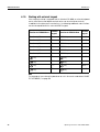
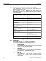
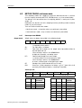
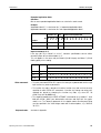
SECOND UNIT
Select second weight unit
Possible units: g, kg, lb, oz, ozt, dwt
Unit
Abbreviation Conversion to g
Kilogram
kg
= 1000 g
Pound
lb
≈ 453.59237 g
Ounce
oz
≈ 28.349523125 g
Troy Ounce
ozt
≈ 31.1034768 g
Pennyweight
dwt
≈ 1.555173843 g
Gram
g
=1g
Comment
On certified weighing platforms only the units permitted by certification appear.
DISPLAY UPDATE
Set display speed of the weight display
Select number of updates per second (UPS).
Possible values: 6, 10, 15, 20 UPS
Comments
• This block only appears when the DISPLAY UPDATE function is supported by the
connected weighing platform.
• The possible settings are dependent on the connected weighing platform.
44
Operating instructions 22012808D 04/07
Settings in the master mode
IND690-Base
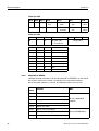
MINWEIGH
Configure minimum weighing-in quantity
MINWEIGH ON
In this setting, the symbol
appears in the display when the weight on the scale
falls below the stored minimum weight.
TYPE
Determining the minimum weight:
CALCULATED The minimum,5 weight is calculated:
U0
Measurement uncertainty when the load approaches 0.
TOL
Required tolerance
SF
Safety factor
MINWEIGH Calculated value based on the parameters entered
above
DIRECT
Enter MINWEIGH value directly
MINWEIGH OFF
No monitoring of the minimum weighing-in quantity (factory setting)
RESET SCALE
Reset weighing platform to factory setting
WEIGHING-PROC ADAPT
VIBRATION ADAPTER
STABILITY DETECTOR
AUTOZERO
AUTOTARA
AUTO CLEAR TARE
RESTART
MINWEIGH
Operating instructions 22012808D 04/07
universal weighing
average conditions
ASD = 2
on
off
off
off
off
45
Settings in the master mode
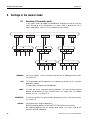
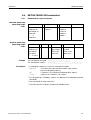
5.5
IND690-Base
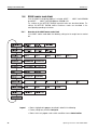
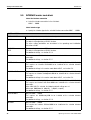
INTERFACE master mode block
Select the interface connection
➜ Select the interface connection in the first block:
COM1 ... COM9.
Select interface type
➜ Specify the interface type for the selected interface connection COM1 … COM9.
COM1 ... COM9
NOT ASSIGNED
If the selected interface connection is not assigned.
GA46
For connecting the printer GA46/GA46-W.
The data is exchanged via an RS232 interface.
The other setting possibilities are described in the operating and installation
instructions GA46.
BARCODE
RFID
For connecting a barcode or RFID reader.
The data is exchanged via an RS232 interface.
For additional settings, see Section 5.5.2.
RS232
This requires an RS232 interface to be connected at the selected interface
connection.
For additional settings, see Section 5.5.1.
IDNET SCALE
Only for COM2 ... COM5 (IND690) or for COM2 ... COM4 (IND690xx, IND690-24V)
This requires an interface IDNet-690 to be installed at the selected interface
connection.
For additional settings in the master mode block SCALE, see Section 5.4.
ANALOG SCALE
Only for COM2 ... COM5 (IND690) or for COM2 ... COM4 (IND690xx, IND690-24V)
This requires an interface AnalogScale-690 to be installed at the selected interface
connection.
For additional settings in the master mode block SCALE, see Section 5.4.
SICS SCALE
Only for COM2 ... COM5 (IND690) or for COM2 ... COM4 (IND690xx, IND690-24V)
This requires an interface SICS-Scale-690 to be installed at the selected interface
connection.
When SICS SCALE is selected, the following default settings are set:
SICS mode, 9600 baud, 8 data bits, 1 stop bit, no parity.
For additional settings, see Section 5.5.1.
ALIBI MEMORY
Only for COM2 ... COM9.
This requires an AlibiMemory-690 to be installed at the selected interface
connection.
For additional settings, see Section 5.5.3.
CL20MA
Only for COM2 ... COM9.
This requires an interface CL20mA-690 to be installed at the selected interface
connection.
For additional settings, see Section 5.5.1.
46
Operating instructions 22012808D 04/07
Settings in the master mode
IND690-Base
COM1 ... COM9
RS422
RS485
Only for COM2 ... COM9.
This requires an interface RS485/422-690 to be installed at the selected interface
connection.
For additional settings, see Section 5.5.1.
4 I/O
Only for COM5/COM6.
This requires an interface 4 I/O-690 with a relay box 4-690 to be installed at the
selected interface connection.
For additional settings, see Section 5.5.4.
RELAY BOX 8
Only for COM2 ... COM9.
This requires an interface RS485/422-690 with a relay box 8-690 to be installed at
the selected interface connection.
For additional settings, see Section 5.5.4.
ANALOG OUTPUT
Only for COM5/COM6.
This requires an interface AnalogOut-690 to be installed at the selected interface
connection.
For additional settings, see Section 5.5.6
ETHERNET
Only for COM2 ... COM9.
This requires Ethernet-690 to be installed at the selected interface connection.
For additional settings, see Section 5.5.7.
PROFIBUS-DP
Only for COM2 ... COM9.
This requires ProfibusDP-690 to be installed at the selected interface connection.
For additional settings, see Section 5.5.8
WLAN
Only for COM2 ... COM9.
This requires WLAN-690 to be installed at the selected interface connection.
For additional settings, see Section 5.5.9
BLUETOOTH
Only for COM2 ... COM9.
This requires Bluetooth-690 to be installed at the selected interface connection. For
additional settings, see Section 5.5.10
USB
Only for COM2 ... COM9.
This requires an interface USB-690 to be installed at the selected interface
connection.
For additional settings, see Section 5.5.1
KEYBOARD PS2
For connecting an external keyboard
Only for COM9
This requires an interface PS2-690 to be installed at COM9.
For additional settings, see Section 5.5.5
Operating instructions 22012808D 04/07
47
Settings in the master mode
5.5.1
IND690-Base
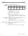
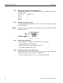
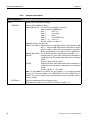
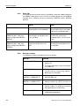
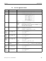
Settings in the master mode blocks RS232, RS422, RS485, CL20mA, USB
RS232, RS422, RS485, CL20mA, USB
OPERATING MODE
1:1 CONNECTION
Weighing terminal and peripheral are directly connected.
BUS SLAVE
For operating the weighing terminal in a bus system.
The following parameters are set automatically for the dialog:
No handshake, no continuous transmission, no transfer string, fixed string framing
C RL F .
The PC is the master, the terminals act as slaves and only transmit when requested
to do so by the master. The master must also wait until after sending out a
command until the slave's answer is received.
Each terminal must be assigned a unique address.
Additional setting:
ENTER TERMINAL ADDRESS. Possible addresses: 1 … 31
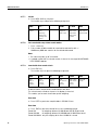
COMMUNICATION
Set communication parameters (factory settings are shown in bold print).
All parameters are shown on a display page and can be set there; for function key
assignment, see page 51.
BITS PER
CHARACTER
Possible settings: 7 bits, 8 bits
STOPBITS
Possible settings: 1 stop bit, 2 stop bits
PARITY
Possible settings: Parity even, parity odd, parity space, parity mark, no parity
BAUDRATE
Possible settings: 150, 300, 600, 1200, 2400, 4800, 9600, 19200, 38400,
57600 baud
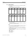
MODE
48
This selection only appears with the RS485 master mode block.
Set operating mode.
This selection does not appear when interface RS485/422-690 is operated in the
BUS SLAVE operating mode.
STANDARD
SETTING
Set operating mode to factory setting:
MMR dialog mode, no handshake, no auto transmission (no continuous
transmission), transfer string: Standard, string framing: CRLF
DIALOG MODE
For dialog between weighing terminal and computer.
For other settings see next section.
PRINT MODE
To print weighing data, e.g. on a form printer.
For other settings see page 50.
Operating instructions 22012808D 04/07
Settings in the master mode
IND690-Base
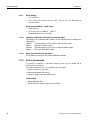
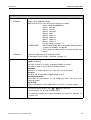
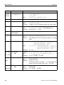
Set dialog mode
DIALOG MODE
Set dialog between weighing terminal and computer
MMR
For information on dialog mode with the MMR command set, see page 68.
All parameters are shown on a display page and can be set there.
HANDSHAKE
Possible settings:
• NO HANDSHAKE
• CL HANDSHAKE – for additional information on the CL handshake, see page
118.
• XON-XOFF PROTOCOL.
AUTOMATIC
CONTINUOUS
TRANSMISSION
This block does not appear with the RS485/422-690 interface.
Possible settings:
• NO AUTO TRANSMISSION.
• AUTO SIR – after each measuring cycle a stabilized or dynamic weight is
transmitted.
• AUTO DIR – weight values are transmitted as with AUTO SIR and additionally, the
special characters in the display are transmitted for a second display.
Fixed communications parameters: 9600 baud, 7 data bits, 2 stop bits,
parity even
• AUTO SR – after each weight change which is greater than the set value, a
motionless weight value and then a dynamic weight value are sent
TRANSFER STRING
This block does not appear with the RS485/422-690 interface.
Possible settings:
• STANDARD – gross, net, tare
• OPTION 082/083 – gross, net, tare in GNT form, see operating instructions,
Option 082.
• USER-DEFINED – enter numbers of the application blocks which are to be
transmitted or printed out.
STRING FRAMING
Possible settings (factory settings are printed in bold print):
• CR Yes/No
• LF Yes/No
• <STX>---<ETX> Yes/No
• BLOCK CHECK CHAR Yes/No
SICS
Dialog mode with Standard Interface Command Set (SICS), see page 81.
STANDARD
Standard setting: no handshake, no auto transmission.
HANDSHAKE
Possible settings as MMR, see above.
AUTOREPEAT
Possible settings as MMR, see above.
AUTO-DIR not possible with SICS.
Operating instructions 22012808D 04/07
49
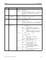
Settings in the master mode
IND690-Base
DIALOG MODE
Set dialog between weighing terminal and computer
TOLEDO CONTINUOUS
For the continuous transmission of net and tare values to METTLER TOLEDO
devices, e.g. to a second display. For a description, see page 79.
This block does not appear with the RS485/422-690 interface.
TRANSFER RATE
Set the data transfer rate
Possible settings: 25%, 33%, 50%, 100%
Factory setting: 100%
CHECKSUM ON
Checksum byte active, factory setting
CHECKSUM OFF
Checksum byte inactive, the transfer format is shortened by 1 character.
TOLEDO SHORT
CONTINUOUS
For the continuous transmission of net values to METTLER TOLEDO devices, e.g. to
a second display. For a description, see page 79.
This block does not appear with the RS485/422-690 interface.
TRANSFER RATE
Set the data transfer rate
Possible settings: 25%, 33%, 50%, 100%
Factory setting: 100%
CHECKSUM ON
Checksum byte active, factory setting
CHECKSUM OFF
Checksum byte inactive, the transfer format is shortened by 1 character.
PE SEND CONTINUOUS
For connecting a PE balance as a reference balance, only with IND690-Count and
Interface CL20mA-690.
Set print mode
PRINT MODE
Configure printout on an external printer
HANDSHAKE
Possible settings:
• NO HANDSHAKE
• XON-XOFF PROTOCOL
LINE LENGTH
Enter number of characters per line.
Possible settings:
1 … 240 characters
Factory setting:
40 characters
LINE FRAMING
Enter ASCII character for line framing.
Possible settings:
ASCII 0 … 255
Factory setting:
ASCII 013 010 (CRLF)
REPORT TYPE
Assignment of one of two possible printout formats to the configured printer. Possible
settings:
50
• REPORT TYPE A
e.g. for barcode printer
• REPORT TYPE B
e.g. for A4 printer
Operating instructions 22012808D 04/07
Settings in the master mode
IND690-Base
PRINT MODE
Configure printout on an external printer
CONFIGURATION
PRINTOUTS
Configuration of the printouts assigned to the individual keys.
For each offered key, the current configuration can be printed out with the key
sequence CHANGE CONFIGURATION, Fu (possibly several times) and PRINT.
TRANSFER KEY
Configuration options:
CODE A KEY
• CHANGE CONFIGURATION
See next section
• DEFAULT SETTING
Key-specific, if existent
• DELETE ALL
All blocks of the data string are deleted
• PAPER FEED
Adjustment range: 0 ... 9 lines
• REPORT ON/OFF
Switch key printout on/off
• # OF COPIES
Setting range: 1 ... 9 copies
Factory setting: 1 copy
...
CODE F KEY
DYNAMIC KEY
PAC KEYS
AUTOMATIC PRINTOUT
Switch automatic printout for transfer key on/off.
When AUTO PRINTOUT ON is selected, a printout for the transfer key is automatically
created for each weight change > x digits.
Possible settings:
1 ... 255 digits (factory setting: 30 digits)
Change configuration
Function keys
The function keys are assigned in CHANGE CONFIGURATION as follows:
<
>
Fu
ADD
↑
Display
previous entry
Display next
entry
Select function
of function key
F5:
ADD, INS etc.
ADD
INS
EDIT
DEL
PRINT
Return to next
highest level;
changes are
not saved
The printout can be edited with function key F5:
ADD
INS
EDIT
DEL
PRINT
Operating instructions 22012808D 04/07
Adds a new entry at the end of the printout.
Inserts a new entry in front of the displayed entry.
Changes into the EDIT mode for the displayed entry to edit the entry.
Deletes the displayed entry.
Creates a key printout.
51
Settings in the master mode
IND690-Base
EDIT mode
Function keys
Display page
The following function keys are available in the EDIT mode:
<–>
<
>
Fu
SAVE
↑
Select
parameters
Set
parameters,
scroll back
Set
parameters,
scroll
forward
Select function
of function key
F5:
SAVE, EDIT
Confirm
changes and
return to
higher level
Cancel EDIT
mode and
return to
higher level;
changes are
not saved
The setting of the parameters of an entry appears in a clear layout on a display page
(example):
TRANSFER KEY
[EDIT]
TYPE: AB
CRLF: YES
STYLE:
FILL: NO
DATA:
First display line
(2/7)
PAD: 01
011-013
Information for orientation in an entry
• Key name
• Mode: EDIT, INS or ADD
• Number of the display entry and total number of entries for the current printout.
TYPE parameter
52
Selection possibilities:
AB
Output content of an application block with or without designation
TEXT
Print out any desired text
CHRn
Insert n of any desired ASCII characters in the line, e.g. for tables;
selection of character via DATA parameter
LINE
Blank line or separator line with any desired alphanumeric characters
DB
Accesses a database field. When a field is printed out, all entries of the
field are listed.
The option DB is only available when the software application supports
access to a database.
The offered database fields are application-specific.
Operating instructions 22012808D 04/07
Settings in the master mode
IND690-Base
STYLE parameter
STYLE determines in which format the designation and content of the application
block are printed; adjustment possibilities:
TYPE
STYLE
AB
DB
Designation and content in grouped style
Designation and content in two lines, grouped style
Designation and content separated with extra blank
spaces
Content alone, left-justified
Content alone, centred
Content alone, right-justified
TEXT
Left-justified
Centred
Right-justified
CRLF parameter
Force line feed; the CRLF parameter is only available for:
•
Text, left-justified
•
Content alone, left-justified
•
Designation and content separated with extra blank spaces
• Type CHRn
FILL parameter
PAD parameter
Show content with leading blank spaces up to maximum available length; the FILL
parameter is only available for:
•
Designation and content separated with extra blank spaces
•
Content alone, left-justified
•
Content alone, centred
Show designation and content separated with x blank spaces
Possible settings: 0 ... 63 extra blank spaces.
The PAD parameter is only available for:
•
Designation and content separated with extra blank spaces
•
Content alone, left-justified
Operating instructions 22012808D 04/07
53
Settings in the master mode
DATA/FIELD parameter
Entry of
DATA parameter
IND690-Base
Depending on the TYPE selected, DATA or FIELD is available.
TYPE
DATA/
FIELD
LINE
DATA
1 alphanumeric character
Entry also possible as ASCII code, see below
AB
DATA
Number of application blocks to be output: xxx
The application block can be further specified with the
following keys:
AB_EXT: _ For selecting read-only memories: xxx_yyy
SUB-BLK: . For selecting a sub-block:
xxx.z or xxx_yyy.z
RANGE: For entering a range:
xxx-xxx or xxx_yyy-yyy
CHRn
DATA
1 alphanumeric character
Entry also possible as ASCII code, see below
TEXT
DATA
Alphanumeric characters
DB
FIELD
Select database field
ENTRY
To enter data or select database fields, the EDIT mode must be active.
1. Press Fu key, repeat if necessary until the assignment of the F5 key changes to
EDIT.
2. Press the EDIT key; an input mask appears.
3. Enter data in the format and with the keys offered.
4. Complete entry with 8.
Enter ASCII code for LINE and CHRn parameters
1. Open the entry mask with the EDIT key.
2. Press IDENT F and enter the ASCII code numerically.
3. Complete the numeric entry with IDENT F.
4. Complete entry with 8.
54
Operating instructions 22012808D 04/07
Settings in the master mode
IND690-Base
5.5.2
BARCODE, RFID
Set barcode or RFID reader
Set barcode or RFID reader
TYPE
DL900/DL910
DLL6000
FEIG PRH100
...
Select barcode or RFID reader.
When one of the barcode or RFID readers is selected, the communication and mode
parameters for the selected barcode or RFID reader are automatically set.
OTHER
For other barcode or RFID readers:
Settings in the sub-blocks COMMUNICATION and MODE as for the blocks RS232/
RS422/RS485/CL20mA/USB, see page 5.5.1.
The PRINT MODE setting is not possible when using barcode or RFID readers!
DESTINATION BLOCK
000/00
Enter the number of the application block and of the subsequent block with which
the barcode or RFID entry is to be described.
When a target block is selected, barcode or RFID information can be read directly
into this block without having to press a key beforehand, see page 27.
AUTOMATIC ENTRY
If AUTOMATIC ENTRY ON is selected, the received barcode or RFID code is shown in
the display and is then accepted as the entry automatically. The display duration
can be set in the TERMINAL master mode block, see page 40.
5.5.3
Setting AlibiMemory
ALIBI MEMORY
Configure contents of the entries of the alibi memory
ENTRY LENGTH
Use E to select from various entries, the contents are shown in the display.
Note
15 CHARACTERS
Gross, tare, date/time, scale number, MinWeigh, tare source; 15 characters
Factory setting
35 CHARACTERS
Same as 1, additionally ID code A (20 characters)
45 CHARACTERS
Same as 1, additionally ID code A (30 characters)
55 CHARACTERS
Same as 1, additionally ID code A (20 characters) + ID code B (20 characters)
55 CHARACTERS
Same as 1, additionally ID code A (20 characters) + ID code C (20 characters)
55 CHARACTERS
Same as 1, additionally ID code A (20 characters) + ID code D (20 characters)
55 CHARACTERS
Same as 1, additionally ID code A (20 characters) + ID code E (20 characters)
55 CHARACTERS
Same as 1, additionally ID code A (20 characters) + ID code F (20 characters)
If an alibi memory had already been initialised and the format is changed, all
previous entries (in the old format) are deleted. For safety, a corresponding notice
appears before initialisation.
Operating instructions 22012808D 04/07
55
Settings in the master mode
5.5.4
IND690-Base
Configure inputs/outputs
4 I/O / RELAY BOX 8
INPUT
56
Operate inputs internally or externally.
INTERNALLY
Factory setting. Additional settings:
CONFIGURE INPUTS Select the desired setting for every input.
Factory setting for IND690-Base:
Input 1
not in use
Input 2
zero setting
Input 3
taring
Input 4
entry (ENTER key)
Input 5 ... 8
not in use
Possible settings: see page 117
Additional settings, only for 4 I/O:
ON/OFF HIGH ACTIVE Factory setting, the weighing terminal is switched off when ON/
OFF = 1. After the digital input has been activated, the display
goes out, and the content of the text read-only memory 021,
factory setting appears in the upper left corner: POWER OFF.
ON/OFF LOW ACTIVE The weighing terminal is switched off when ON/OFF = 0.
ON TIME
Delayed switch-on: After the On signal has been activated, the
weighing terminal still remains switched off for the configured
period.
Possible settings: 0 to 9 seconds
Off TIME
Delayed switch-off: After the Off signal has been activated, the
weighing terminal still remains switched on for the configured
period.
Possible settings: 0 ... 9 seconds
Note: The input ON/OFF has priority over the keyboard, i.e. the weighing terminal
can only be switched on again in the POWER OFF state via the ON/OFF input! In
addition, entry into the master mode is permitted via the F6 key to be able to correct
incorrect settings.
EXTERNALLY
Inputs are independent of the weighing functions.
Read status of the inputs with the AR707 command, see page 110.
Operating instructions 22012808D 04/07
Settings in the master mode
IND690-Base
4 I/O / RELAY BOX 8
OUTPUT
Operate outputs internally or externally.
INTERNALLY
Factory setting. Additional settings:
CONFIGURE OUTPUTS Select the desired setting for every output.
Factory setting for IDN690-Base:
Output 1 Delta low
Output 2 Delta ok
Output 3 Delta high
Output 4 Stable
Output 5 Setpoint 1
Output 6 Setpoint 2
Output 7 Setpoint 3
Output 8 Setpoint 4
Possible settings: see page 117
SETPOINT MODE
With SETPOINT MODE ON 8 configurable fixed or dynamic
set points are available, see page 58.
To this purpose a setpoint has to be assigned to at least one
output.
EXTERNALLY
Outputs are independent of the weighing functions.
Set the outputs via the AW706... command, see page 110.
I/O TEST
Testing of the function and state of the inputs and outputs of one or two connected
8-690 relay box(es)
If an input or output is set (high), the display indicates its number.
If an input or output is not set (low), the display indicates –.
Set outputs
Switch over the outputs with the keys 1 to 8 of the numerical keypad.
Set inputs
Set inputs, e.g. by connecting a supply voltage (+24 V).
Two 8-ID7 relay boxes
Switch back and forth between the two 8-690 relay boxes with key 9 of the
numerical keypad.
Exit I/O TEST
Exit the I/O test and the master mode with the 0 key of the numerical keypad.
Comments
• During the I/O tests only the keys
,
T
and 8 are active.
• Serial interfaces can be used during the I/O test.
• The possible functions for the inputs and outputs are listed in the Appendix, see
Section 10.4.
Operating instructions 22012808D 04/07
57
Settings in the master mode
SETPOINT MODE ON –
defining set points
IND690-Base
After SETPOINT MODE ON is selected, the following input mask appears for the setpoints
1 ... 4 (Example):
SP1: F↑
AO12
W1
1.2345 KG
SP2: F↓
AO13
W2
0.5678 KG
SP3: D↑
AO12
ALL
SP4: D↓
AO11
ALL
4 parameters can be set for each set point:
a) Type of set point
F↑
fixed set point, ascending
F↓
fixed set point, descending
D↑ dynamic set point, ascending
D↓ dynamic set point, descending
Fixed set point
Set point value is specified in the master mode and cannot be
changed in the weighing mode.
Dynamic set point Set point value is specified in the weighing mode, see page 21.
Ascending
Digital output is set when the value of the application block
concerned is greater than or equal to the set point value.
Decending
Digital output is set when the value of the application block
concerned is less than or equal to the set point value.
b) Application block
Weight value to which the set point refers. All application blocks with a valid weight
unit (kg, g, lb, oz, ozt, dwt, pc) are possible.
Factory setting: Application block 012, net weight
c) Scale
W1 ... W4 or ALL for all scales
d) Set point value
With dynamic set points the weight value is entered in the normal mode, see page
21.
Configuring switching points 5 – 8
➜ With F4 >>, change to the input mask for switching points 5 – 8.
58
Operating instructions 22012808D 04/07
Settings in the master mode
IND690-Base
5.5.5
KEYBOARD PS2
Configuring external keyboard
Select keyboard layout of connected external keyboard
Possible setting: English-USA, English-UK, German, French, Dutch, Italian, Spanish,
Finnish, Russian
5.5.6
Configuring AnalogOut-690
The functionality of AnalogOut-690 is dependent on the version of your weighing
terminal.
ANALOG OUTPUT
SCALE
ALL SCALES
Select weighing platform from which the weight values are to be output at the
interface AnalogOut-690.
This block only appears when several weighing platforms are connected.
Factory setting: All weighing platforms
Weight values can be output by all connected weighing platforms at the AnalogOut690 interface.
The assignment of a weighing platform to the AnalogOut-690 interface can be
or the command AW010...
changed with
SCALE 1
...
SCALE 4
Only weight signals of the selected weighing platform can be output via the
AnalogOut-690 interface
START-STOP MODE
When the selected weight value or the selected number of pieces is within the
specified en start and stop values, a current/voltage signal in the specified range
will be output at the AnalogOut-690 interface.
U/I
10 V
20 mA
Stop value
Start value
0
Start value
Stop value
Weight
For additional settings, see page 61.
Operating instructions 22012808D 04/07
59
Settings in the master mode
IND690-Base
ANALOG OUTPUT
DELTATRAC MODE
In this operating mode the net weight value on the AnalogOut-690 interface is
output in the factory setting, provided DeltaTrac is active.
If no DeltaTrac target value is entered, 0 V / 0 mA are output.
For additional settings, see page 61.
∆W-∆T MODE
In this operating mode flows are measured via the weight change per time in the
supply or catch container.
Example 1: Weighing in with a flow rate of 4 kg/sec.
Example 2: Subtractive weighing with a flow rate of 3 kg/sec.
starting value of the analog voltage signal: 10 V.
In both cases a change in the flow rate of 1 kg/sec. results in a change in the
analog voltage signal of 2 V.
For additional settings, see page 61.
60
Operating instructions 22012808D 04/07
Settings in the master mode
IND690-Base
Parameter for Start-Stop mode
AB
Application block number for the weight value to be output at the
AnalogOut-690 interface.
Factory setting: Application block 012, net weight
VALUE
Starting value of the analog output signal
Factory setting: 0 V
Possible settings: 0 V – 10 V or 0 mA – 20 mA
Stop value of the analog output signal
Factory setting: 10 V
Possible settings: 0 V – 10 V or 0 mA – 20 mA
WEIGHT
Weight value at which the analog output is to start.
Factory setting: 0 g or 0 kg
Weight value from which the maximum value of the analog signal is to
be output.
Factory setting: Maximum load of weighing platform
Parameter for DeltaTrac mode
AB
Application block number for the weight value to be output at the
AnalogOut-690 interface.
Factory setting: Application block 012, net weight
V/mA AT ZERO
Starting value of the analog output signal
Factory setting: 0 V
Possible settings: 0 V – 10 V or 0 mA – 20 mA
V/mA AT TARGET
Stop value of the analog output signal
Factory setting: 10 V
Possible settings: 0 V – 10 V or 0 mA – 20 mA
TOLERANCE
+/– deviation from stop value of analog signal when the target
weight tolerance is reached
Factory setting: Tolerance = 0 V
Parameters for the ∆W-∆T MODE
AB
Application block number for the weight value to be output at the
AnalogOut-690 interface.
Factory setting: Application block 012, net weight
∆W-∆T
Value for the change in the analog output signal in the case of a
weight change of one unit per second.
START VALUE
Starting value of the analog output signal
Factory setting: 0 V
Possible settings: 0 V – 10 V or 0 mA – 20 mA
Operating instructions 22012808D 04/07
61
Settings in the master mode
5.5.7
IND690-Base
Configuring Ethernet-690
The weighing terminal can only be operated on a network with a valid IP address,
subnet mask and gateway address (if the weighing terminal is to route connections
to another partial network). Ask your system administrator for these addresses.
ETHERNET
Configuring Ethernet-690
COMMUNICATION
For adaptation of the communication parameters between weighing terminal and
the Ethernet module, see page 48.
MODE
For adaptation of the communication mode, see page 48.
IP ADDRESS
IP address entry
SUBNET MASK
Net mask entry
GATEWAY
Gateway address entry
Note
Additional information on the configuration of the Ethernet-690 network card and
information on troubleshooting can be downloaded from the website of the
manufacturer: www.WuT.de.
Checking Ethernet-690
Condition
You require a PC with Windows on which the protocol TCP/IP is installed. The PC
must be operated in the same network segment as the weighing terminal with
Ethernet-690.
Conducting test
With DOS entry window
1. Open DOS entry window.
2. Enter TELNET xxx.xxx.xxx.xxx 8000 (xxx.xxx.xxx.xxx = IP address) and
confirm with 8.
The PC reports the following in a Telnet window
**************************
* Com-Server Highspeed *
**************************
The message means that the Ethernet-690 network card is operable. The PC and
the weighing terminal can communicate with each other via interface
commands, see chapter 6.
3. Close Telnet window.
With browser
1. Start browser, e.g. Internet Explorer.
2. Enter xxx.xxx.xxx.xxx (xxx.xxx.xxx.xxx = IP address) and confirm with 8.
The PC reports a login window.
3. Enter password (factory setting: no password).
The configuration menu of the Ethernet-690 network card appears.
62
Operating instructions 22012808D 04/07
Settings in the master mode
IND690-Base
5.5.8
Configuring ProfibusDP-690
PROFIBUS-DP
Configuring ProfibusDP-690
NODE ADDRESS
Select desired node address in range 001 to 126.
Factory setting: 3
OPERATING MODE
Set type and word length of user data parameter VALUE.
Consistent over
2 words
valid module pair in GSD file
16-BIT-INTEGER 2(+2)W AI
16-BIT-INTEGER 2(+2)W AO
16-BIT-INTEGER /
4 WORDS
2 words
16-BIT-INTEGER 2(+2)W AI
16-BIT-INTEGER 2(+2)W AO
32-BIT-FLOATINGPOINT
4 words
32-BIT-FLOATING-POINT 4W AI
32-BIT-FLOATING-POINT 4W AO
16-BIT-INTEGER /
2 WORDS
S/P MODE
(use 2x)
(use 2x)
Set type and use of setpoint.
UNIVERSAL
Each setpoint can be set and read independently of others.
CHECKWEIGHING
As soon as setpoints 1 and 2 are set, DeltaTrac CHECKWEIGHING will be activated
with SP1 = setpoint and SP2 = tolerance (in %, in 16-bit integer mode with 2
decimal places).
In read table current state BELOW (SP1), GOOD (SP2) or ABOVE (SP3) can be read
off.
FILLING
As soon as setpoints 1 and 2 are set, DeltaTrac CHECKWEIGHING will be activated
with SP1 = setpoint and SP2 = tolerance (in %, in 16-bit integer mode with 2
decimal places). In addition, SP3 and SP4 can also be loaded as any desired
setpoints.
In read table current state GOOD (SP1), ABOVE (SP2), SP3 REACHED (SP3) or SP4
REACHED (SP4) can be read off.
I/P MODE
Set request for identification data in Input mode.
After setting the user data command INPUT MODE in the write table, the selected
request for input is automatically carried out and the entries are saved in the
application blocks 094 to 099.
The user data response INPUT MODE RUNNING remains set while the input mode is
active.
A
Code A is requested.
A+B
Code B and Code A are always requested.
A+B+C
Code C, Code B and Code A are always requested.
A+B+C+D
Code D, Code C, Code B and Code A are always requested.
A+B+C+D+E
Code E, Code D, Code C, Code B and Code A are always requested.
A+B+C+D+E+F
Code F, Code E, Code D, Code C, Code B and Code A are always requested.
Operating instructions 22012808D 04/07
63
Settings in the master mode
IND690-Base
PROFIBUS-DP
Configuring ProfibusDP-690
EXP. AB AREA
Input of up to three expanded application blocks for constants which can be
accessed when writing applications blocks.
Example
Input
enables access to
021
application blocks 021_001 to 021_999
046
application blocks 046_001 to 046_999
071
application blocks 071_001 to 071_999
CONFIGURE INPUTS
Select the desired setting for every input.
Factory setting for the IND690-Base:
Input 1
not in use
Input 2
zero setting
Input 3
taring
Input 4
entry (8 key)
Input 5
...
not in use
Input 8
Further settings: see page 119
CONFIGURE OUTPUTS
Select the desired setting for every output.
Factory setting for the IND690-Base:
Output 1
Delta low
Output 2
Delta ok
Output 3
Delta high
Output 4
Stable
Output 5 ... 8
Setpoint 1 ... 4
Further settings: see page 119
TEST MODE
Activation of the information display. In line 3 and 4 write and read tables are
displayed as follows:
64
1
Read table
2
Write table
3
Operating mode (internal)
4
Value (hexadecimal)
5
Command/response bits
6
Inputs/outputs (hexadecimal)
Operating instructions 22012808D 04/07
Settings in the master mode
IND690-Base
5.5.9
Configuring WLAN-690
The weighing terminal can only be operated in a wireless network with a valid IP
address, subnet mask etc. Ask your system administrator for these parameters.
WLAN
Configuring WLAN-690
INFO
Displays the type and software version of the WLAN module.
Same function as the key sequence "INFO 50" in the operating mode.
STATUS
Displays the current status of the WLAN module: Radio channel used, data rate of
connection, transmission and reception quality, MAC address of the currently
connected access point.
Same function as the key sequence "INFO 51" in the operating mode.
COMMUNICATION
For adaptation of the communication parameters between weighing terminal and
the WLAN module, see page 48.
MODE
For adaptation of the communication mode, see page 48.
IP ADDRESS
IP address entry
PORT NUMBER
Port number entry
GATEWAY
Gateway address entry
SUBNET MASK
Net mask entry
SSID
Entry of wireless-network name (ServiceSetIdentifier).
WEP-KEY
WEP key entry, with 5 characters (64 bit key) or 13 characters (128 bit key).
AUTHORISATION
Switch authorisation on/off
PORT TYPE
Set WLAN architecture: Ad hoc or infrastructure
AUTO CONNECT
Input of the IP address and port number of a partner to which establishing of a
connection is tried cyclically – if a connection does not exist.
Operating instructions 22012808D 04/07
65
Settings in the master mode
5.5.10
IND690-Base
Configuring Bluetooth-690
BLUETOOTH
Configure Bluetooth-690
INFO
Displays the type, software version and manufacturer of the Bluetooth module.
Same function as the key sequence "INFO 60" in the operating mode.
STATUS
Displays the current status of the Bluetooth module: own Bluetooth address, own
Bluetooth name, user service/COM port and name of the Bluetooth module to which
there is currently a connection.
Same function as the key sequence "INFO 61" in the operating mode.
COMMUNICATION
Adaptation of the communication parameters between weighing terminal and WLAN
module, see Page 48.
MODE
Adaptation of the communication mode, see Page 48.
PASSKEY
Switching the passkey interrogation on/off and entering the passkey, if switched on.
CONNECT
All reachable Bluetooth modules are displayed. The connection to one of these
modules can then be made or an existing connection can be broken.
66
Operating instructions 22012808D 04/07
Interface description
IND690-Base
6
Interface description
6.1
General
To exchange data with a computer, the weighing terminal is equipped with an RS232
interface. Up to 8 additional interfaces are available as an option.
The interfaces operate independently of each other, can be used simultaneously and
can be adjusted individually, see section 5.5.
To operate the serial interfaces in the dialog mode, one of the following METTLER
TOLEDO command sets must be selected in the master mode:
• MMR command set, see section 6.2.
• METTLER TOLEDO Continuous mode, see section 6.3.
• METTLER TOLEDO SICS command set, see section 6.4.
Note
In order to avoid data loss, do not operate the interfaces in unsolicited mode. In
particular if the handshake is deactivated, ensure that the host waits for a response
after every command before a new command is sent.
Operating instructions 22012808D 04/07
67
Interface description
IND690-Base
6.2
6.2.1
MMR command set
Syntax and formats of communication
Commands and responses for transmitting weights have the following formats:
Command format
when transmitting
weight formats
Identification
Response format
when transmitting
weight formats
Identification
Example
Data formats
Character
sequence for
specification of
command
(1 … 4
characters)
Character
sequence for
specification of
response
(2 … 3
characters)
_ Weight value
1 … 8 digits,
number of digits
variable
_ Weight value
10 digits, rightjustified,
filled out with
blank spaces
Command Tare specification
Response Tare specification
_ Unit
1…3
characters,
number of
characters
variable
_ Unit
3 characters,
left-justified,
filled out with
blank spaces
Framing
Definable in
master mode,
factory setting:
CRLF
Framing
definable in
master mode,
factory setting:
CRLF
{T|_|1[3[.[2[9[5|_|k[g}
{T[B[H|_|_[_[_[_[1[3[.[2[9[5|_|k[g[_}
• The following symbols are used in the following command description:
Weight value
Unit
Text_n
10 characters with sign and decimal point, right-justified
(with preceding blank spaces)
3 characters, left-justified (with following blank spaces)
maximum of n characters, left-justified
• The string framing is mandatory, however it is not contained in the following
command description!
• Enter commands as ASCII characters. The following ASCII characters are available:
20 hex/32 deci … 7F hex/127 deci, see page 116.
BUS SLAVE
operating mode
(RS485)
Example
68
In the BUS SLAVE operating mode each command and each response begins with a
code for the terminal address.
Terminal address 1 … 9
Code "1" … "9"
(31H … 39H)
Terminal address 10 … 31 Code "a" … "v"
(61H … 76H)
Command to terminal 3: {3|S}
Response from terminal 3:{3[S[_|_|_[_[_[_[1[2[.[7[6[5|_|k[g[_}
Operating instructions 22012808D 04/07
Interface description
IND690-Base
6.2.2
Command overview
Command
Meaning
Page
R0 / R1
Switch keypad on/off
70
KD / KE
Switch individual key on/off
70
Z
Set weight display to zero after weighing platform stabilization
70
U_…
Change over terminal to a different weight unit
70
T
Tare
71
T_…
Specify tare weight
71
DY_…
Specify DeltaTrac target value
72
S
Transmit in case of weighing platform stabilization
72
SI
Transmit independent of weighing platform stabilization
72
SIR
Transmit repeatedly independent of weighing platform stabilization
73
SR
Transmit stabilized weight values repeatedly depending on a weight
change
73
SR_…
Transmit repeatedly depending on weighing platform stabilization with
specification of an excursion value
73
SX
Transmit data record after weighing platform stabilization
74
SXI
Transmit data record independent of weighing platform stabilization
74
SXIR
Transmit data record repeatedly independent of weighing platform
stabilization
74
ARNo.
Read information of application block
75
AWNo._…
Write to application block
75
D_…
Write to display
75
P_…
Print alphanumeric characters or barcodes on the GA46
76
DS
Trigger acoustic signal
76
ID
Interrogate terminal identification
76
W_...
Actuating digital outputs
77
Operating instructions 22012808D 04/07
69
Interface description
IND690-Base
6.2.3
Command description
Switch keypad on or off
Command
{R[0}
{R[1}
Switch on keypad
Switch off keypad
Response
{R[B}
Keypad switched on or off
Comments
• Factory setting: Keypad switched on.
• When the keypad is switched off, the terminal cannot be operated manually.
Switch individual key on or off
Command
Response
Comments
{K[E|_|x[x}
{K[D|_|x[x}
{K[B}
Switch on key with key number xx
Switch off key with key number xx
Key switched on or off
• Factory setting: Keys switched on.
• See table in the Appendix for key numbers.
Set zero
Command
{Z}
Set gross weight display to zero after weighing platform stabilization,
effect as when
Response
Comments
{Z[B}
{Z[-}
{Z[+}
is pressed.
Weighing platform set to zero
Command cannot be executed: Zero-set range dropped below
Command cannot be executed: Zero-set range exceeded
• Setting to zero is not possible when the weighing platform stabilizes in the zeroset range.
• With some weighing platform types setting to zero deletes a saved tare weight.
This is indicated with the message TA, see section 6.2.4.
Changing over to different weight unit
Command
70
{U|_|Unit} Change over weight display to different weight unit
{U}
Change over weight display to first weight unit
Response
{U[B}
Weight display changed over to different weight unit
Comment
Possible units: g, kg, lb, ozt, oz, dwt
Operating instructions 22012808D 04/07
Interface description
IND690-Base
Tare
Command
{T}
Tare weighing platform:
After the weighing platform stabilizes, the current weight value is saved
as the tare weight and the weight display is set to zero with the weight
placed on the platform.
Effect as when
T
is pressed.
{T|_|Tare weight (weight value)|_|Unit}
Specify tare weight:
The content of the tare memory is overwritten with the specified tare
weight and the net weight is displayed.
{T[_}
Response
{T[B[_|_|Tare weight (weight value)|_|Unit}Weighing platform is tared
{T[B[H|_|Tare weight (weight value)|_|Unit}Weighing platform is tared with
{T[-}
{T[+}
Comments
Effect as when PT , 0 … 9, 8 sequence is pressed.
Delete tare weight.
specified weight
Command cannot be executed: Tare range dropped below
Command cannot be executed: Tare range exceeded
• Taring is only possible when the weighing platform stabilizes within the tare
range.
• The tare weight is always transmitted in the first weight unit.
• Each taring command overwrites the content of the tare memory with the new tare
weight.
• Taring with an unloaded weighing platform deletes the tare memory. On some
weighing platform types a zero set is carried out in the unloaded state. This is
displayed with the message ZA, see section 6.2.4.
• On not certified weighing systems the tare weight is automatically rounded to the
current increment.
• On certified weighing systems: Tare range for MultiRange only in first increment
range.
Example
Command: {T}
Response: {T[B[_|_|_[_[_[_[1[2[.[6[5[0|_|k[g[_}
Operating instructions 22012808D 04/07
71
Interface description
IND690-Base
Specify DeltaTrac target value
Command
Response
Comments
{D[Y|_|Target weight (weight value)|_|Unit|_|Lower tolerance|_|Unit|_|
Upper tolerance|_|Unit}
{D[Y}
Specify DeltaTrac target value
Delete DeltaTrac target value
{D[B}
DeltaTrac target value loaded/deleted
• Observe limit values, see page 19
• Also possible: {A[W[0[2[0[..., see page 106
Example
Command: {D[Y|_|4[.[5|_|k[g|_|5|_|%|_|4|_|%}
Response: {D[B}
Transmit content of display
Command
Response
72
{S}
{S[I}
Transmit a stabilized weight when weighing platform is stabilized.
Transmit a stabilized or dynamic weight independent of weighing
platform stabilization.
{S[_|_|Weight value|_|Unit}Stabilized weight value transmitted
{S[D|_|Weight value|_|Unit}Dynamic weight value transmitted
{S[I}
Invalid weight
{S[I[-} Weighing platform in underload range
{S[I[+} Weighing platform in overload range
Operating instructions 22012808D 04/07
Interface description
IND690-Base
Transmit content of display repeatedly
Command
{S[I[R}
{S[R}
Transmit stabilized or dynamic weight values after each measuring
cycle independent of weighing platform stabilization.
Transmit the next stabilized weight value after a weight change (e.g.
different item) and one dynamic and the next stabilized weight value
after each deflection > 30 d.
{S[R|_|Deflection weight (weight value)|_|Unit}
Transmit the next stabilized weight value and, depending on the
specified deflection, a dynamic weight value after a weight change
greater than the specified deflection value.
Response
{S[_|_|Weight value|_|Unit}Transmit stabilized weight value repeatedly
{S[D|_|Weight value|_|Unit}Transmit dynamic weight value repeatedly
Comment
Stop command with {S}, {S[I} command or by interrupting the interface
Example
Command: {S[R|_|1[4[0|_|k[g}
Responses: {S[_|_|_[_[_[_[2[0[0[.[0[0|_|k[g}1st item
{S[D|_|_[_[_[_[3[4[5[.[8[5|_|k[g}
{S[_|_|_[_[_[_[4[1[0[.[5[0|_|k[g}2nd item
Operating instructions 22012808D 04/07
73
Interface description
IND690-Base
Transmit data record
Command
Response
Transmit a data record with stabilized weight values after weighing
platform stabilization.
Effect as if 8 is pressed.
{S[X[I} Transmit a data record with stabilized or dynamic weight values
independent of weighing platform stabilization.
{S[X[I[R} Transmit data records with stabilized or dynamic weight values
repeatedly independent of weighing platform stabilization.
{S[X}
{S[X[_|_|Application block|_|_|Application block|… }
{S[X[_|_|Application block |
{S[X[_[_|A|No.|_|Data record|
Data record with stabilized weight values transmitted
{S[X[D|_|Application block|_|_|Application block|… }
{S[X[_|_|Application block |
{S[X[_[_|A|No.|_|Data record|
Data record with dynamic weight values transmitted
{S[X[I} Invalid value
{S[X[I|-} Weighing platform in underload range
{S[X[I|+} Weighing platform in overload range
Comments
• Number of application block: three-digit with leading zeros.
• The content of the corresponding application block is contained in data record,
see chapter 7. Standard data record consists of 3 blocks:
{S[X[_|_|A[0[1[1|_|Gross weight (weight value)|_|Unit|_|_|
{S[X[_|_|A[0[1[2|_|Net weight (weight value) |_|Unit{_|_|
{S[X[_|_|A[0[1[3|_|Tare weight (weight value) |_|Unit}
The continuous transmission of data records started with the {S[X[I[R}
command can be stopped with the {S[X} or {S[X[I} command.
Example
Command: {S[X[I}
Response: Standard data record
{S[X[D|_|A[0[1[1|_|_[_[_[_[2[3[.[6[5[0|_|k[g[_|
_|_|_|A[0[1[2|_|_[_[_[_[2[1[.[6[5[0|_|k[g[_|
_|_|_|A[0[1[3|_|_[_[_[_[_[2[.[0[0[0|_|k[g[_}
74
Operating instructions 22012808D 04/07
Interface description
IND690-Base
Read application block
Command
Response
Comments
{A[R|No.}
Read content of application block
{A[B|_|Information}
Content of application block transmitted
• Transmitted information is dependent on application block, see chapter 7.
• Number of application block must be entered as 3 digits with preceding zeros.
Write to application block
Command
Response
Comments
{A[W|No.|_|Information} Write to application block
{A[W|No.}
Reset application block
{A[W|No.|_}
Delete application block
{A[B}
Written to application block
• Information to be entered is dependent on target block, see chapter 7.
• Deleting and resetting have same effect.
Write to display
Command
Response
Comments
{D|_|Text_20}
{D|_}
{D}
Write to display
Switch display to dark
Set display to normal status
{D[B}
Written to display
• Character stock: ASCII characters 20 hex/32 deci … 7F hex/127 deci, see page
116.
• Watch upper and lower case.
Operating instructions 22012808D 04/07
75
Interface description
IND690-Base
Alphanumeric printout on GA46 printer
Command
Response
Comments
{P|_|Text_48}
{P|_|$|!|1|Text_48}
{P|_|$|!|2|Text_48}
{P|_|$|!|3|Text_48}
{P|_|$|!|A|Text_48}
{P|_|$|!|B|Text_48}
{P|_|$|!|C|Text_48}
{P|_}
Print text as per setting
Print text in small type
Print text in normal type
Print text in large type
Print text in small type and bold print
Print text in normal type and bold print
Print text in large type and bold print
Print blank line
{P[B}
Alphanumeric characters printed
• Character stock: ASCII characters 20 hex/32 deci … 7F hex/127 deci, see page
116.
• Text is printed in last selected type size.
• Watch upper and lower case.
Barcode printout on GA46 printer
Command
Response
Comments
{P|_|$|#|1|Text_20, barcode-specific}
{P|_|$|#|2|Text_8, barcode-specific}
{P|_|$|#|3|Text_13, barcode-specific}
{P|_|$|#|4|Text_20, barcode-specific}
{P|_|$|#|5|Text_20, barcode-specific}
{P|_|$|#|6|Text_20, barcode-specific}
{P|_|$|#|7|Text_20, barcode-specific}
{P|_|$|#|8|Text_20, barcode-specific}
{P|_}
Print Code 39
Print EAN 8
Print EAN 13
Print EAN 128
Print Code 2 of 5
Print Code 2 of 5 interleaved
Print Code 128
Print EAN 128
Print blank line
{P[B}
Barcode printed
• Character stock: ASCII characters 20 hex/32 deci … 7F hex/127 deci, see page
116.
• With Code 39, 3 barcodes can be printed next to each other.
Separating characters: $$ or HT (ASCII character 09 hex/9 deci).
Arrangement of barcodes: Barcode 2, Barcode 1, Barcode 3.
Acoustic signal
Command
{D[S}
Generate short acoustic signal (beep tone) in terminal
Response
{D[B}
Acoustic signal generated in terminal
Identification
Command
Response
76
{I[D}
Interrogate identification of terminal
{I[D[7|_|Program number of Pac}
Operating instructions 22012808D 04/07
Interface description
IND690-Base
Actuating digital outputs
Command
{W|_|Status}
Switch individual digital outputs on or off
{W|_|Status 1|_|Time 1|_|Status 2|_|Time 2|_|...|Status 4|_|Time 4|_|Status 5}
{W}, {W|_}
Status:
Response
Comments
Trigger time sequence of status changes of digital outputs
Reset all outputs to logical 0
Time:
Each output is assigned a value. The total of the values of those
outputs which are to be closed is indicated as the "Status".
Digital output 1
1
Digital output 2
2
Digital output 3
4
Digital output 4
8
Digital output 5
16
Digital output 6
32
Digital output 7
64
Digital output 8
128
All outputs open
0
All outputs closed
255
1 ... 99999 ms
{W[B}
Digital outputs set
• Max. 5 statuses "Status" and 4 intervals "Time" are possible. After sequence has
been run, digital outputs freeze in last status "Status".
• A break in the port has no effect on the outputs.
• If terminal receives a new W command before time sequence has been run,
ongoing sequence will be aborted immediately.
• If limits for "Status" and "Time" are not adhered to, error message EL appears on
4 I/O-690 interface or 8-690 relay box.
Examples
Command: {W|_|5}
Digital outputs 1 and 3 are closed, all others opened
Command: {W|_|1|_|1[0[0[0|_|3[2|_|5[0[0[0|_|3[3|_|5[0[0|_|0}
triggers following sequence:
Operating instructions 22012808D 04/07
77
Interface description
IND690-Base
6.2.4
Terminal messages – only with RS232, RS422, CL20mA and USB
In the dialog mode the weighing terminal transmits an acknowledgement to the
computer each time a key is pressed.
When this pressing of a key is replaced with an interface command, the
acknowledgement only differs in the second character in the response format which
is part of the command:
Function
Key
Acknowledgement
Set zero
{Z[A}
Tare
{T[A}... (see command T)
Specify tare weight
{T[A[H|… (see command T_ …)
Change over unit
{U[A|_|Unit}
Transmit data record in
case of weighing platform
stabilization
{S[T|_[_|… (see command SX)
Switch over weighing
platform
{S[A|_[_|n}
Dynamic weighing
{A[A[0[1[6|_|Weight value|_|Unit}
Identification A … F
n = weighing platform 1 … 3
A…F
{K[x|_|Identification}
x = A, B, C, D, E, F
20 characters, right-justified
Function keys
6.2.5
78
F1 … F6
{K[F|_|x} x = I, J, K, L, M, N
Fault messages
Fault messages always consist of 2 characters and a string frame.
The string frame can be defined in the master mode (section 5.5.2).
{E[T}
Transmission error
The terminal transmits a transmission error for errors in the received bit
sequence, e.g. parity errors, missing stop bit.
{E[S}
Syntax error
The terminal transmits a syntax error when the received characters
cannot be processed, e.g. command does not exist.
{E[L}
Logic error
The terminal transmits a logic error when a command cannot be
executed, e.g. when an attempt is made to write to a write-protected
application block.
Operating instructions 22012808D 04/07
Interface description
IND690-Base
6.3
METTLER TOLEDO continuous mode
These operating modes are suitable for continuous data transmission in real time
from the weighing terminal to METTLER TOLEDO devices, e.g. to a second display.
The data are even transmitted when the weighing platform is moving or the gross
weight = 0.
Commands can also be sent to the weighing terminal, permitting remote control of
certain keys on the terminal.
There are 2 different continuous modes:
• Continuous mode – net and tare values are continuously transmitted.
• Short continuous mode – only net values are continuously transmitted.
6.3.1
Output format
Data output from IND690
Weight values are always transmitted in the following format:
STX
SB1
STX
SB2
SB3
DF1
DF2
CR
CHK
ASCII characters 02 hex/2 deci, character for "start of text"
is required by some printers
For status bytes, see below
Data field with 6 digits for the weight value transmitted without a
decimal point and unit
When counting is active in the IND690-Count:
6 digits for the quantity, no leading zeroes
Data field with 6 digits for the tare weight;
is not transmitted in the short continuous mode
When counting is active in the IND690-Count:
6 zeroes, not transferred in Short Continuous mode
Carriage return (ASCII character 0D hex/13 deci)
Checksum (2-part complement of binary sum of 7 lower bits of all
previously transmitted characters, including STX and CR)
SB...
DF1
DF2
CR
CHK
Status byte SB1
Bit 6
Bit 5
Bit 4
Bit 3
Bit 2
0
1
Rounding / Increment
Bit 1
Bit 0
Decimal position
Bit 4
Bit 3
Rounding/
Increment
Bit 2
Bit 1
Bit 0
Decimal
position
0
1
1
0
0
0
XXXX00
1
0
2
0
0
1
XXXXX0
1
1
5
0
1
0
XXXXXX
0
1
1
XXXXX.X
1
0
0
XXXX.XX
1
0
1
XXX.XXX
1
1
0
XX.XXXX
1
1
1
X.XXXXX
Operating instructions 22012808D 04/07
79
Interface description
IND690-Base
Status byte SB2
Bit 6
Bit 5
Bit 4
Bit 3
Bit 2
Bit 1
Bit 0
0
1
0 lb
0 Stabilization
0 Normal
status
0 Positive
sign
0 Gross
value
1 kg
1 Movement
1 Underload/
overload
1 Negative
sign
1 Net
value
Status byte SB3
6.3.2
80
Bit 6
Bit 5
Bit 4
Bit 3
Bit 2
0
1
0
0 Basic state
1 Print request
Bit 2
Bit 1
Bit 0
Weight value
0
0
0
kg / lb (SB2 Bit 4)
0
0
1
g
0
1
0
t
0
1
1
oz
1
0
0
ozt
1
0
1
dwt
1
1
0
ton
1
1
1
free unit
Bit 1
Bit 0
Weight value
Commands to IND690
Individual command characters can be transmitted to the IND690 in the text format.
One function each on the terminal is assigned to these command characters.
After a command character is received, the following functions are executed:
Command
Function
C
Delete tare
P
Print or send transfer string
T
Taring
Z
Setting to zero
Tx.xxx
Specify tare value
Sxxxx
Specify reference quantity
Sx.xxx
Specify reference weight
Ax.xxx
Specify reference piece weight
Note
for every application
software
only for IND690-Count
Operating instructions 22012808D 04/07
Interface description
IND690-Base
6.4
6.4.1
METTLER TOLEDO SICS command set
Communication syntax and formats
Command format when
transmitting weight
values
Identification
Response format when
transmitting weight
values
Identification
Example
Data formats
String of
characters for
specification of
command
(1 … 4
characters)
String of
characters for
specification
of response
(1 ... 2 char.)
_ Weight value
1 … 10
characters
_ Status
1 char.
_ Unit
Framing
1 ... 3
characters,
number of
characters
variable
_ Weight value
10 char.,
right-justified,
filled in with
blank char.
CRLF
_ Unit
3 char., leftjustified,
filled in with
blank char.
Framing
CRLF
Tare specification command {T[A|_|1[3[.[2[9[5|_|k[g}
Tare specification response {T[A|_|A|_|_[_[_[_[1[3[.[2[9[5|_|k[g[_}
• The following symbols are used in the command description:
Weight value
Unit
"Text_n"
10 numbers with sign and decimal point, right-justified
(with preceding blank spaces)
3 characters, left-justified (with following blank spaces)
maximum of n characters, left-justified
• The string framing is mandatory, however it is not listed in the following command
description!
• Enter commands as upper-case letters.
• Text to be entered must always be placed in quotation marks.
Operating instructions 22012808D 04/07
81
Interface description
IND690-Base
6.4.2
Command
Command overview
Meaning
Page
I0
Transmit list of all available SICS commands
83
I1
Transmit SICS level and SICS versions
83
I2
Transmit scale data (terminal, platform)
83
I3
Transmit scale software version (program number)
84
I4
Transmit serial number
84
S, SI, SIR
Transmit display contents
84
Z
Set to zero
85
@
Reset
85
D
Write display
85
DW
Weight display
85
K
Keyboard monitoring
86
SR
Transmit stable weight values repeatedly depending on a weight change
87
T
Taring
87
TI
Tare immediately
88
TA
Specify tare weight
88
TAC
Delete tare weight
89
SX, SXI, SXIR
Transmit data record
89
R0, R1
Switch keyboard on or off
90
U
Change over to different weight unit
90
DS
Acoustic signal
90
AR
Read application block
90
AW
Write application block
91
DY
Specify DeltaTrack target value
91
P
Print text or barcode
92
W
Actuating digital outputs
93
Level 0
Level 1
Level 2
Level 3
82
Operating instructions 22012808D 04/07
Interface description
IND690-Base
6.4.3
Command description
Transmit SICS commands
Command
Response
{I[0}
Transmit SICS commands
{I[0|_|B}
{I[0|_|0|_|"I0"}
{I[0|_|0|_|"I1"}
...
{I[0|_|1|_|"D"}
...
{I[0|_|2|_|"SX"}
...
{I[0|_|3|_|"AR"}
...
{I[0|_|A}
Transmit SICS levels and SICS versions
Command
Response
{I[1}
Transmit SICS levels and SICS versions
{I[1|_|A|_|"x1"|_|"x2"|_|"x3"|_|"x4"|_|"x5"}
x1 = 0123 Scale with SICS levels 0, 1, 2 and 3
x2
Version or implemented SICS0 commands
x3
Version or implemented SICS1 commands
x4
Version or implemented SICS2 commands
x5
Version or implemented SICS3 commands
{I[1|_|I} Command understood, cannot be executed at this time
Comments
• On the SICS level only fully implemented levels are executed.
• With the SICS version all levels are specified.
Transmit scale data
Command
Response
Example
{I[2}
Transmit data from weighing terminal and weighing platform(s)
{I[2|_|A|_|"text"}
{I[2|_|A|_|"IND690-Count IZ05 15.000 kg IZ10 32.000 kg"}
Operating instructions 22012808D 04/07
83
Interface description
IND690-Base
Transmit scale software version
Command
Response
Example
{I[3}
Transmit software version from weighing terminal and weighing
platform(s)
{I[3|_|A|_|"text"}
{I[3|_|A|_|"IP63-0-0100I IZ05-0-0301 IZ10-0-0221"}
Transmit serial number
Command
Response
Example
Comment
{I[4}
Transmit serial number of weighing terminal
{I[4|_|A|_|"text"}
{I[4|_|A|_|"1234567"}
The response to I4 appears automatically following switch-on and after the Reset
command (@).
Transmit display contents
Command
{S}
{S[I}
{S[I[R}
84
Transmit a stable weight value when the weighing platform is at a
standstill.
Transmit a stable or a dynamic weight value, regardless of whether the
weighing platform is at a standstill.
Transmit a stable or a dynamic weight value after each measuring
cycle, regardless of whether the weighing platform is at a standstill.
Response
{S|_|S|_|Weight value|_|Unit}Stable weight value transmitted
{S|_|D|_|Weight value|_|Unit}Dynamic weight value transmitted
{S|_|I}
Invalid value
{S|_|-}
Weighing platform in underload range
{S|_|+}
Weighing platform in overload range
Comment
Stop {S[I[R} command with {S}, {S[I}, {S[R}, @ command or disconnect
port.
Operating instructions 22012808D 04/07
Interface description
IND690-Base
Set to zero
Command
{Z}
Set gross weight display to zero after weighing platform comes to a
standstill, effect as when
Response
{Z|_|A}
{Z|_|I}
{Z|_|-}
{Z|_|+}
Comment
is pressed
Weighing platform set to zero
Command cannot be executed: e.g. standstill not achieved or another
command is currently being executed
Command cannot be executed: Zero-set range dropped below
Command cannot be executed: Zero-set range exceeded
Can only be set to zero when the weighing platform comes to a standstill in the
zero-set range.
Reset
Command
Response
Comments
{@}
Reset weighing terminal to the state maintained after Power On
{I[4|_|A|_|"text"}Serial number
• All running applications and functions are cancelled.
• The tare memory is reset to zero.
Write display
Command
Response
{D|_|"Text_20"} Write display
{D|_|""}
Darken display
{D|_|A}
{D|_|A}
{D|_|I}
{D|_|L}
Comment
Display written; the complete text appears left-justified in the
display, marked with a symbol, e.g. with *
Display written; the end of the text appears left-justified in the
display with the beginning cut off, marked with a symbol, e.g.
with *
Command cannot be executed
Command understood, parameters defective
A symbol in the display, e.g. *, indicates that an invalid weight value is displayed.
Weight display
Command
Response
{D[W}
Switch over main display into the weight mode
{D[W|_|A}
{D[W|_|I}
The main display shows the current weight value
Command understood, but cannot be executed
Operating instructions 22012808D 04/07
85
Interface description
IND690-Base
Keyboard monitoring
Command
{K[_[1}
{K[_[1}
{K[_[3}
{K[_[4}
Response
{K|_|A}
{K|_|I}
{K|_|L}
When a key is pressed, execute the function, but do not transmit
anything (factory setting)
When a key is pressed, do not execute the function and do not
transmit anything
When a key is pressed, do not execute the function, but transmit the
key code {K[_[C[_[x} or, when the key is pressed longer, transmit
{K[_[R[_[x} and {K[_[C[_[x}
When a key is pressed, execute the function and transmit the function
code {K[_[A[_[x}
If the function cannot be executed immediately, the function code for
the start of the function {K[_[B[_[x} or {K[_[A[_[x} for the end
of the function is transmitted.
Command understood or function successfully executed
Command understood, but currently cannot be executed, e.g. no
keyboard present
Command understood, parameters defective
Key codes
{K[_[R[_[x}
{K[_[C[_[x}
Key x was pressed briefly and released again immediately
Key x was pressed for approx. 2 sec.
Function codes x
See table in the Appendix for function codes
Comments
• The factory setting is active after switch-on, after the Reset command and after
exiting the master mode.
• Only one K command is ever active at one time.
86
Operating instructions 22012808D 04/07
Interface description
IND690-Base
Transmit stable weight values repeatedly depending on a weight change
Command
{S[R|_|Excursion weight (weight value)|_|Unit}
{S[R|}
Response
After a weight change greater than the specified excursion weight,
transmit alternately the next stable weight value and a dynamic weight
value depending on the specified excursion.
If no excursion weight is entered, the weight change must be at least
12.5 % of the last stable weight value, however at least 30 d.
{S|_|S|_|Weight value|_|Unit}Current stable weight value transmitted
Weight change
{S|_|D|_|Weight value|_|Unit}Dynamic weight value transmitted
{S|_|I} Command cannot be executed
{S|_|L} Command understood, parameters defective
{S|_|-} Weighing platform in underload range
{S|_|+} Weighing platform in overload range
Comment
Example
Stop command with command {S}, {S[I}, {S[I[R}, @ or disconnect the port.
Command: {S[R|_|1[4[0|_|k[g}
Responses: {S|_|S|_|_[_[_[_[2[0[0[.[0[0|_|k[g}1st item
{S|_|D|_|_[_[_[_[3[4[5[.[8[5|_|k[g}
{S|_|S|_|_[_[_[_[4[1[0[.[5[0|_|k[g}2nd item
Taring
Command
Response
{T}
{T|_|S|_|Tare weight (weight value)|_|Unit}
{T|_|I}
{T|_|-}
{T|_|+}
Comments
Tare weighing platform:
After the weighing platform comes to a standstill, the current weight
value is saved as a tare weight and the weight display set to zero with
the weight on the platform.
Effect as when TARE key is pressed.
Weighing platform tared,
stable tare value
Taring not carried out
Command cannot be executed: Tare range dropped below
Command cannot be executed: Tare range exceeded
• Each taring command overwrites the contents of the tare memory with the new
tare weight.
• Taring with unloaded weighing platform clears the tare memory. On some
weighing platform models, setting to zero is carried out in the unloaded state.
• On non-certified weighing systems the tare weight is automatically rounded off to
the current increment.
• On certified weighing systems: Tare range with MultiRange only in first increment
range.
Operating instructions 22012808D 04/07
87
Interface description
IND690-Base
Tare immediately
Command
Response
{T[I}
Tare weighing platform immediately.
{T[I|_|S|_|Tare weight (weight value)|_|Unit}
Weighing platform tared, stable tare value
{T[I|_|D|_|Tare weight (weight value)|_|Unit}
Weighing platform tared, dynamic tare value
{T[I|_|I} Taring not carried out
{T[I|_|L} Command cannot be executed
{T[I|_|-} Command cannot be executed: Tare range dropped below
{T[I|_|+} Command cannot be executed: Tare range exceeded
Comments
• Each taring command overwrites the contents of the tare memory with the new
tare weight.
• Following a dynamic tare value, a stable weight value can be specified.
However, this value is not exact.
Specify tare weight
Command
{T[A|_|Tare weight (weight value)|_|Unit}
Specify tare weight:
The contents of the tare memory are overwritten with the specified tare
weight and the net weight is displayed.
Effect as when the key sequence
Response
, 0 ... 9, 8 is pressed.
{T[A|_|A|_|Tare weight (weight value)|_|Unit}
{T[A|_|I}
{T[A|_|L}
{T|_|-}
{T|_|+}
Comments
PT
Weighing platform tared with the specified value
Command not carried out
Command understood, parameters defective
Command cannot be executed: Tare range dropped below
Command cannot be executed: Tare range exceeded
• The contents of the tare memory are overwritten with the specified tare value.
• On non-certified weighing systems the tare weight is automatically rounded off to
the current increment.
• On certified weighing systems: Tare range with MultiRange only in first increment
range.
Example
88
Command: {T[A|_|1[2[.[6[5[0|_|k[g}
Response: {T[A|_|A|_[_[_[_[1[2[.[6[5[0|_|k[g[_}
Operating instructions 22012808D 04/07
Interface description
IND690-Base
Delete tare weight
Command
Response
{T[A[C}
Delete tare weight.
{T[A[C|_|A}
{T[A[C|_|I}
Weighing platform tared with the specified weight
Command not carried out
Transmit data record
Command
Response
After the weighing platform comes to a standstill, transmit a data
record with stable weight values.
Effect as when 8 is pressed.
{S[X[I} Transmit a data record with stable or dynamic weight values,
regardless of whether the weighing platform is at a standstill.
{S[X[I[R} Repeatedly transmit a data record with stable or dynamic weight
values, regardless of whether the weighing platform is at a standstill.
{S[X}
{S[X|_|S|_|Application block|_|_|Application block|… }
{S[X[ _|_|Application block |
{S[X [_[_|A|No.|_|Data record|
Data record with stable weight values transmitted
{S[X|_|D|_|Application block|_|_|Application block|… }
{S[X[ _|_|Application block |
{S[X [_[_|A|No.|_|Data record|
Data record with dynamic weight values transmitted
{S[X|_|I} Command cannot be executed
{S[X|_|-} Weighing platform in underload range
{S[X|_|+} Weighing platform in overload range
Comments
• Number of application blocks: three-place with preceding zeros.
• The contents of the corresponding application block is contained in the data
record, see chapter 7. The standard data record consists of 3 blocks:
{S[X|_|S|_|A[0[1[1|_|Gross weight (weight value)|_|Unit|_|_|
{S[X[_ |_|A[0[1[2|_|Net weight (weight value) |_|Unit{_|_|
{S[X[ _|_|A[0[1[3|_|Tare weight (weight value) |_|Unit}
The continuous transmission of data records started with the {S[X[I[R}
command can be stopped with the commands {S[X} or {S[X[I}.
Example
Command: {S[X[I}
Response: Default data record
{S[X|_|D|_|A[0[1[1|_|_[_[_[_[2[3[.[6[5[0|_|k[g[_|
_|_|A[0[1[2|_|_[_[_[_[2[1[.[6[5[0|_|k[g[_|
_|_|A[0[1[3|_|_[_[_[_[_[2[.[0[0[0|_|k[g[_}
Operating instructions 22012808D 04/07
89
Interface description
IND690-Base
Switch keyboard on or off
Command
Response
Comments
{R[0}
{R[1}
Switch on keyboard
Switch off keyboard
{R[0|_|A} Keyboard switched on
{R[1|_|A} Keyboard switched off
• Factory setting: Keyboard switched on.
• When the keyboard is switched off, the terminal cannot be manually operated.
Changing over to different weight unit
Command
{U|_|Unit}
{U}
Change over weight display to different weight unit
Change over weight display to the first weight unit
Response
{U|_|A}
{U|_|I}
Weight display switched over to another weight unit
Impermissible weight unit
Comment
Possible units: g, kg, lb, ozt, oz, dwt
Acoustic signal
Command
Response
{D[S}
Generate short acoustic signal (beep) in the terminal
{D[S|_|A} Acoustic signal generated in the terminal
Read application block
Command
Response
Comments
{A[R|_|No.}
Read contents of the application block
{A[R|_|A|_|Information}
Contents of the application block transmitted
• The transmitted information is dependent on the application block, see chapter 7.
• The number of the application block must be entered as a three-place number
with preceding zeros.
90
Operating instructions 22012808D 04/07
Interface description
IND690-Base
Write application block
Command
Response
Comments
{A[W|_|No.|_|Information}
{A[W|_|No.}
{A[W|_|No.|_}
Write application block
Reset application block
Delete application block
{A[W|_|A}
{A[W|_|I}
{A[W|_|L}
Application block written
Application block not present
Application block cannot be written
• The information to be entered is dependent on the target block, see chapter 7.
• Deleting and resetting have the same effect.
Specify DeltaTrac target value
Command
{D[Y|_|Target weight (weight value)|_|Unit|_|Lower tolerance|_|Unit|_|
Upper tolerance|_|Unit}
{D[Y}
Response
Comments
Specify DeltaTrac target value
Delete DeltaTrac target value
{D[Y|_|A} DeltaTrac target value loaded/deleted
• Observe limit values, see page 19
• Also possible: {A[W|_|0[2[0[..., see page 106
Example
Command: {D[Y|_|4[.[5|_|k[g|_|5|_|%}
Response: {D[Y|_|A}}
Operating instructions 22012808D 04/07
91
Interface description
IND690-Base
Print text or barcode with GA46 printer
Command
Response
Comments
{P|_|Text_48}
Print text as per setting
{P|_|$|!|1|Text_48} Print text in small print
{P|_|$|!|2|Text_48} Print text in normal print
{P|_|$|!|3|Text_48} Print text in large print
{P|_|$|!|A|Text_48} Print text in small type and bold print
{P|_|$|!|B|Text_48} Print text in normal type and bold print
{P|_|$|!|C|Text_48} Print text in large type and bold print
{P|_|$|#|1|Text_20, barcode-specific}
Print code 39
{P|_|$|#|2|Text_8, barcode-specific}
Print EAN 8
{P|_|$|#|3|Text_13, barcode-specific}
Print EAN 13
{P|_|$|#|4|Text_20, barcode-specific}
Print code 128
{P|_|$|#|5|Text_20, barcode-specific}
Print code 2 of 5
{P|_|$|#|6|Text_20, barcode-specific}
Print code 2 of 5 interleaved
{P|_|$|#|7|Text_20, barcode-specific}
Print code 128
{P|_|$|#|8|Text_20, barcode-specific}
Print EAN 128
{P|_}
Print blank line
{P|_|A}
{P|_|L}
Alphanumeric characters printed
no GA46 present
• Character stock: ASCII character 20 hex/32 dec ... 7F hex/127 dec, see page 116.
• Printing is carried out in the font size last selected.
• Watch upper and lower case.
92
Operating instructions 22012808D 04/07
Interface description
IND690-Base
Actuating digital outputs
Command
{W|_|Status}
Switch individual digital outputs on or off
{W|_|Status 1|_|Time 1|_|Status 2|_|Time 2|_|...|Status 4|_|Time 4|_|Status 5}
{W}, {W|_}
Status:
Response
Comments
Trigger time sequence of status changes of digital outputs
Reset all outputs to logical 0
Time:
Each output is assigned a value. The total of the values of those
outputs which are to be closed is indicated as the "Status".
Digital output 1
1
Digital output 2
2
Digital output 3
4
Digital output 4
8
Digital output 5
16
Digital output 6
32
Digital output 7
64
Digital output 8
128
All outputs open
0
All outputs closed
255
1 ... 99999 ms
{W|_|A}
Digital outputs set
• Max. 5 statuses "Status" and 4 intervals "Time" are possible. After sequence has
been run, digital outputs freeze in last status "Status".
• A break in the port has no effect on the outputs.
• If terminal receives a new W command before time sequence has been run,
ongoing sequence will be aborted immediately.
• If the limits for "Status" and "Time" are not adhered to when operating the
interface types 4 I/O or relay box 8, the fault message EL appears.
Examples
Command: {W|_|5}
Digital outputs 1 and 3 are closed, all others opened
Command: {W|_|1|_|1[0[0[0|_|3[2|_|5[0[0[0|_|3[3|_|5[0[0|_|0}
triggers following sequence:
Operating instructions 22012808D 04/07
93
Interface description
IND690-Base
6.4.4
6.5
6.5.1
Error messages
Error messages always consist of 2 characters and a string limit.
The string limit can be defined in the master mode (section 5.5.1).
{E[T}
Transmission error
The terminal transmits a transmission error for errors in the received bit
sequence, e.g. parity error, missing stop bit.
{E[S}
Syntax error
The terminal transmits a syntax error when it cannot process the
received characters, e.g. command not present.
{E[L}
Logic error
The terminal transmits a logic error, when a command cannot be
executed, e.g. when an attempt is made to write an non-writeable
application block.
Profibus DP communication with a PLC
Overview
The ProfibusDP-690 is designed for operation as a slave on the Profibus DP. This
provides the following possibilities with a master PLC also connected to the Profibus
DP:
• Access to the weight values of the weighing platform connected to the weighing
terminal
• Operation of the weighing platforms connected to the weighing terminal (zero-set,
taring, setting specified tare values, etc.)
• Triggering key presses, transmitting data strings or display of texts
94
Operating instructions 22012808D 04/07
Interface description
IND690-Base
6.5.2
Data formats
All user data are transmitted in a compressed, up to 4-word long format.
Write table
Format for transmitting user data from the PLC to the ProfibusDP-690.
Read table
Format for the transmission of user data from ProfibusDP-690 to the PLC.
Structure of the write and read table
The write and read table are similarly structured and contain the following sections:
• Value (16-bit integer or 32-bit floating point) for the transmission of weight
values, application block numbers, etc.
• Commands or the corresponding responses with a total of 16 bits
• Control of 16 digital I/Os
6.5.3
Handshake
As certain commands can not always be executed immediately by the scale, e.g.
taring with a restless weighing platform, 3 handshake bits of the PLC allow clear
monitoring of the success of its commands:
1. The PLC starts a command by setting the corresponding command bit and also
toggles COMMAND VALID in the write table. All other command bits are 0.
2. The weighing terminal responds with the current data of the read table. If it was
possible to completely process the command, the COMMAND EXECUTED bit is
toggled. Otherwise COMMAND EXECUTED remains unchanged.
3. The PLC recognises whether it can transmit the next command or must repeat the
last one from COMMAND EXECUTED and transmits the write table to the weighing
terminal.
4. The weighing terminal recognises from the status change of the COMMAND
VALID bit that it should carry out the next command. In addition, the weighing
terminal also detects whether the last command has been executed or is still
running. If the PLC attempts to start new commands before the previous one has
been confirmed by the weighing terminal with a status change of COMMAND
VALID, the weighing terminal ignores this new command.
6.5.4
Commands and responses
All commands available to the PLC and the corresponding responses are shown in
the following two tables.
Data direction PLC -> IND690 Write table
Data direction IND690 -> PLC Read table
Operating instructions 22012808D 04/07
95
Interface description
IND690-Base
Write table
16-Bit
Integer Word 0
2 Words
Word 1
16-Bit
Integer Word 0
4 Words
Word 1
Word 2
Word 2
Word 3
Command
16 Digital I/O AB data
32-Bit
Floating
Point
Bit
Word 0
Word 1
Value
Value
16-Bit
32-Bit Floating Point
0
Word 3
Command valid
Toggle-bit for all commands
1
Bits 1/2/3: Selection of read-table value, read/write AB
0/0/0 = Display
0/0/1 = Key No.
0/1/0 = Gross
0/1/1 = Write AB
2
Mantissa
3
4
1/0/0 = Net
1/0/1 = Read AB
1/1/0 = Tare
1/1/1 = Not in use
Bits 4/5/6: Selection of write-table value
6
0/0/0 = Empty
0/0/1 = Setpoint 1
0/1/0 = Key No.
0/1/1 = Setpoint 3
7
Taring
5
Mantissa
8
Delete tare
9
Set to zero
10
1/0/0 = Tare specification
1/0/1 = Setpoint 2
1/1/0 = Fixed Text No.
1/1/1 = Setpoint 4
or
Displaying or
evaluating
inputs of
external I/O
module
ENTER key
Exponent
11
Input mode
12
Switch keyboard on/off
13
Bits 13/14/15: Selection of weighing platform
14
0/0/0 = None
1/0/0 = Scale 1
0/1/0 = Scale 2
15
96
Sign
Sign
Setting of
IND690
outputs
Data for
writing an
application
block
Tolerance
specifications are
handled in
% if the
sign is set
to 1.
1/1/0 = Scale 3
0/0/1 = Scale 4
1/0/1= Sum scale
Sign
Operating instructions 22012808D 04/07
Interface description
IND690-Base
Read table
16-Bit
Integer Word 0
2 words
Word 1
16-Bit
Integer Word 0
4 words
Word 1
Word 2
Word 2
Word 3
Command
16 Digital I/O Not in
Use
32-Bit
Floating
Point
Bit
Word 0
Word 1
Value
Value
16-Bit
32-Bit Floating Point
0
Word 3
Command executed
Toggle-bit for all commands
1
Error command
2
Movement
Mantissa
3
Net
4
Error scale (overload/underload...)
5
Key(s) was/were pressed
6
Input mode active
7
Mantissa
Setpoint 2 reached
9
Setpoint 3 reached
10
or
Setpoint 1 reached
8
Setpoint 4 reached
Exponent
11
1 = keyboard blocked, 0 = keyboard unblocked
12
Reserved
13
Bits 13/14/15: Current weighing platform
14
0/0/0 = None
1/0/0 = Scale 1
0/1/0 = Scale 2
15
Sign
Showing or
reading of
IND690 inputs
Displaying or
setting outputs
of external I/O
module
1/1/0 = Scale 3
0/0/1 = Scale 4
1/0/1= Sum scale
Sign
Notes on commands
If the command requires parameters, they will be transmitted either as an integer
value or as a floating point value depending on the operating mode set.
Exception: The commands READ/WRITE APPLICATION BLOCK and PRESS KEY
always expect integer values as parameters.
Operating instructions 22012808D 04/07
97
Interface description
Read commands
IND690-Base
• The read commands Display value, Net, Gross, Tare, Key and Application block
overwrite the cyclically transmitted display values with the required data. The data
are transmitted as 16-bit integers or 32-bit floating points. As soon as the
COMMAND EXECUTED bit is toggled, these values must be evaluated immediately
by the PLC, as in the next cycle the value in the read table is overwritten again with
the current weight value.
• The response to the READ KEY NUMBER command (write table bits 1/2/3 = 0/0/1)
is transmitted in the Word 0 (16-bit integer) or in Word 1 (32-bit floating point).
The low byte contains the keyboard code, the high byte the function key code.
The weighing terminal can store a maximum of 10 keys for being called via the
READ KEY NUMBER command. If they are not called, the oldest key actuations are
overwritten.
After reading out the last stored key, the KEY WAS PRESSED bit is reset. The key
memory is cleared after the device is switched on and after the master mode is
exited.
Reading and writing
application blocks
• When writing an application block, the desired data are simultaneously transferred
with Word 3. For this reason, writing application blocks is only possible in 16-bit
integer/4-word mode.
• Only application blocks with the formats "numeric" or "weight value" can be read
or written. When writing, certain tolerance (sub-)blocks (e.g. with DeltaTrac) can
be intentionally written with the format "percent" by setting the sign to "1".
• If a non-existent block or an alphanumeric block is selected, the IND690 responds
with ERROR COMMAND.
The requested data are supplied in the 16-bit integer mode in the same format as
the weight value, and in the 32-bit floating point mode floating point values are
always transmitted.
The application block number in the write table must be entered as a value (Word 0
in 16-bit integer mode, Word 1 in 32-bit floating point mode) in the following format
for the READ APPLICATION BLOCK and WRITE APPLICATION BLOCK commands:
"Basic" application block
Sub-block no.
Example
98
Exp.
Application block number
Bit 15 14 13 12 11 10 9
S S S S E E A
8
A
7
A
6
A
5
A
4
A
3
A
2
A
1
A
0
A
AB 10
0
0
0
0
0
0
0
0
0
0
0
0
1
0
1
0
AB 20, sub-block 2
0
0
1
0
0
0
0
0
0
0
0
1
0
1
0
0
Operating instructions 22012808D 04/07
Interface description
IND690-Base
Expanded application block
Condition
One or more expanded application blocks are selected in master mode.
Example
Application block 21 is selected as the 1st expanded application block,
application block 46 is selected as the 2nd expanded application block.
Sub-block no.
Exp.
Index of the expanded AB
Bit 15 14 13 12 11 10 9
S S S S E E A
Example
8
A
7
A
6
A
5
A
4
A
3
A
2
A
1
A
0
A
AB 21_007
0
0
0
0
0
1
0
0
0
0
0
0
0
1
1
1
AB 46_005, SB 1
0
0
0
1
1
0
0
0
0
0
0
0
0
1
0
1
Input of tolerances in %
If the sign (bit 15) in Word 3 is set to 1, tolerance specifications can be written
accurately down to one decimal place in %.
This rule applies in the same way for Word 0 (16-bit integer) and Word 1 (32-bit
floating point) when reading.
Example
Write commands
Decimal
Binary
15 14 13 12 11 10 9
8
7
6
5
4
3
2
1
0
100.0 %
–1000
1
0
0
0
0
0
1
1
1
1
1
0
1
0
0
0
1%
–10
1
0
0
1
1
0
0
0
0
0
0
0
1
0
1
0
0.1 %
–1
1
0
0
0
0
0
0
0
0
0
0
0
0
0
0
1
• The write command PRESS KEY requires the low byte keyboard code and the high
byte function key code as parameters.
• The function key code is based on the active function keys and must be correctly
specified for each PRESS KEY command. A function key change can also automatically be forced by changing the function key code, e.g. from REF 10
(3301 hex) to X10 (0004 hex).
• The setpoints loaded via the WRITE SETPOINT X commands (e.g. Setpoint 1: write
table bits 4/5/6 = 0/0/1) are deleted after switch-on and each time the master
mode is run. The Tolerance parameter in the setpoint modes Checking and Filling
must be specified in the 16-bit integer mode with 2 decimal places, e.g. 1025 for
10.25 %.
Keyboard codes
See table in Appendix
Operating instructions 22012808D 04/07
99
Interface description
IND690-Base
6.5.5
Digital I/Os
The operating mode of an I/O interface (4 I/O-690 or a relay box 8-690) installed on
the IND690 is dependent on where the I/Os are located (directly on the IND690 or
externally on the Profibus) and on the parameters CONTROL INPUTS, CONTROL
OUTPUTS.
Outputs
Inputs
No I/Os on IND690
The weighing terminal controls
external outputs via the read table.
The weighing terminal reads
external inputs from the write table
and executes predefined actions.
I/Os on IND690 (4 I/O-690 or
8-690 relay box), inputs and
outputs configured to CONTROL
INTERNAL
The weighing terminal controls
internal outputs and displays these
in the read table.
The weighing terminal reads
internal inputs and executes
predefined actions; the PLC has no
access.
I/Os on IND690 (4 I/O-690 or
8-690 relay box), inputs and
outputs configured to CONTROL
EXTERNAL
The PLC controls the outputs of the
weighing terminal via the write
table.
The weighing terminal reads
internal inputs and displays these in
the read table.
6.5.6
Messages in display
The following messages may appear briefly in the display:
Message
Meaning
PROFIBUS NOT ACTIVE!
• Initialisation processes are still running on
Profibus DP.
• The weighing terminal is not yet connected to
the Profibus DP.
100
PROFIBUS ACTIVE
• Readiness restored,
e.g. after switch-on, exiting master mode or
following a bus interruption.
PROFIBUS – ERROR BCC RX
PROFIBUS – ERROR BCC TX
• Weighing terminal or field bus module have
detected a BCC error.
PROFIBUS – ERROR DATA RX
PROFIBUS – ERROR DATA TX
• Communication error weighing terminal <–>
Field bus module: e.g. not ETX, Uart error, etc.
PROFIBUS – TIMEOUT IND690
• Communication error weighing terminal <–>
Field bus module: The weighing terminal does
not respond within the defined time.
PROFIBUS – ERROR CONF.
• The field bus module has not received the
configuration data properly.
Operating instructions 22012808D 04/07
Interface description
IND690-Base
6.5.7
GSD file
The GSD file required for communication with the ProfibusDP-690 is available from
METTLER TOLEDO Service or can be downloaded from the Profibus GSD Library at
http://www.profibus.com.
6.5.8
Profibus DP-690 demo kit
For a demonstration and test of all commands with a normal PC, ask METTLER
TOLEDO Customer Service for the ProfibusDP-690 demo kit.
Operating instructions 22012808D 04/07
101
Application blocks
7
IND690-Base
Application blocks
Application blocks are internal information memories in which weighing data,
calculated quantities, configuration data or character sequences entered with the
keypad are stored. The content of the application blocks can be read out or written to
with a computer.
When the GA46 printer is connected, the assignment of the application blocks can be
printed out, see operating instructions for the GA46 printer.
7.1
Syntax and formats
The syntax and formats are dependent on the command set selected in the dialog
mode, see page 49.
7.1.1
Read application block
Read
{A[R|No.}
{A[R|_|No.}
MMR command set
SICS command set
The weighing terminal receives the command from the
computer to read out the content of the "No." application
block. Possible formats for "No." are:
xxx
Entire application block
xxx.zz
Sub-block of an application block
xxx_yyy
Read-only memory
xxx_yyy.zz Sub-block of a read-only memory
This read command is not contained in the following
description of the application blocks.
Response
{A[B|_|Information}
MMR command set
{A[R|_|A|_Information} SICS command set
As a response the weighing terminal transmits the content
of the "No." application block to the computer.
This response is contained in the following description of
the application blocks in the MMR version.
Example
Command MMR
Command SICS
{A[R|0[2[1[_[0[0[1}
{A[R|_|0[2[1[_[0[0[1}
Read out tare memory 1.
Response MMR
Response SICS
102
{A[B|_|_[_[_[_[_[_[1[0[.[5|_|k[g[_}
{A[R|_|A|_[_[_[_[_[_[1[0[.[5|_|k[g[_}
Operating instructions 22012808D 04/07
Application blocks
IND690-Base
Note
If an application block is not in use, the weighing terminal transmits the corresponding
number of blank spaces in place of the data.
For example, when Tare Memory 1 is not in use, the weighing terminal transmits the
following response:
{A[B|_|_[_[_[_[_[_[_[_[_[_|_|_[_[_} (MMR) resp.
{A[W|_|A|_|_[_[_[_[_[_[_[_[_[_|_|_[_[_} (SICS)
7.1.2
Write to application block
Write
{A[W|No.|_|Information}
{A[W|_|No.|_|Information}
MMR command set
SICS command set
The weighing terminal receives the command from the
computer to write to the "No." application block.
This command is contained in the following description
of the application blocks in the MMR version.
{A[B}
{A[W|_|A}
MMR command set
SICS command set
The weighing terminal transmits a confirmation to the
computer.
This response is not contained in the following
description of the application blocks.
Command MMR
Command SICS
{A[W|0[2[1[_[0[0[1|_|1[2[.[0|_|k[g[_}
{A[W|_|0[2[1[_[0[0[1|_|1[2[.[0|_|k[g[_}
Response
Example
Write to tare memory 1.
Response MMR
Response SICS
{A[B}
{A[W|_|A}
Notes
• Only those application blocks can be written to for which the corresponding AW
command is listed in the following description.
• An application block can consist of one or more sub-blocks, and the numbering of
the sub-blocks begins with 1.
• The sub-blocks of an application block can each contain a maximum of
20 characters.
• The sub-blocks are separated with $$ or HT (ASCII character 09 hex/9 deci):
{A[W|No.|_|Sub-block 1|$[$|Sub-block 2|$[$|…|Sub-block n}(MMR) resp.
{A[W|_|No.|_|Sub-block 1|$[$|Sub-block 2|$[$|…|Sub-block n} (SICS)
• Extensive application blocks are displayed so that each sub-block begins in a new
line.
• To write to individual sub-blocks, enter the corresponding number of $ characters.
If only sub-block 1 is written to, the $ characters are eliminated,
e.g. sub-block 3 written to: {A[W|No.|_|$[$|$[$|Sub-block 3}(MMR) resp.
{A[W|_|No.|_|$[$|$[$|Sub-block 3}(SICS).
Operating instructions 22012808D 04/07
103
Application blocks
IND690-Base
7.1.3
Data formats
• In the following description of the application blocks the following data formats are
used:
Weight value
Unit
Number_n
Text_n
10 digits with sign and decimal point, right-justified
(with preceding blank space)
3 characters, left-justified (with following blank spaces)
Number, n digits, right-justified (with preceding blank spaces)
maximum of n characters
If the SICS command set is used, "Text" must always be placed
in inverted commas.
• Conclude commands and responses with the string frame CRLF
(ASCII characters CR = 0D hex/13 deci, LF = 0A hex/10 deci).
The string frame is not contained in the following description.
7.1.4
Read and write application blocks with the SICS command set
In the following description, the application blocks are shown in the syntax for the
MMR command set. When used with the SICS command set, please observe the
following SICS conventions, also see sections 7.1.1 to 7.1.3 :
• A blank space must be entered between AR or AW and the application block
number: E.g. {A[R|_|No.}
• The command identification is repeated in the response and a blank space and the
character A added:
{A[R|_|A|_|Information} application block transmitted and
{A[W|_|A} application block written.
• Texts entered or transmitted are always in inverted commas.
Example
Read application block for CODE A
Command: {A[R|_|0[9[4}
Response: {A[R|_|A|_|"Article"}
Write application block for CODE A
Command: {A[W|_|0[9[4|_|"Article"}
Response: {A[W|_|A}}
104
Operating instructions 22012808D 04/07
Application blocks
IND690-Base
7.2
List of the application blocks
No.
Content
Format
001
Terminal type
Response:
{A[B|_|Mettler–Toledo_IND690}
002
Program number
Response:
{A[B|_|IP60-0-0xxxx|_}
004
Serial number
Response:
{A[B|_|Identification (Text_20) |_[_|
SN Mainboard (Number_20)|_[_|
SN Scale 1 (Number_14) |_[_|
SN Scale 2 (Number_14) |_[_|
SN Scale 3 (Number_14) |_[_|
SN Scale 4 (Number_14) |_[_|
SN Terminal (Number_7)}
{A[W|0[0[4|_|Identification (Text_20)}
Write:
005
006
Keyboard
Transfer key
Response:
Write:
Note:
{A[B|_|Keyboard}
{A[W|0[0[5|_|$|$|Text}
Only possible as long as input active on IND690. The text is
then written into the input field
Response:
Write:
Note:
{A[B|_|Keys|_[_|key number}
{A[W|0[0[6|_|$|$|2[4}
See table in the Appendix for key numbers
007
007.01
007.02
Current gross weight
(2nd weight unit)
Response:
{A[B|_|Weight value|_|Unit}
{A[B|_|Weight value}
{A[B|_|Unit}
008
008.01
008.02
Current net weight
(2nd weight unit)
Response:
{A[B|_|Weight value|_|Unit}
{A[B|_|Weight value}
{A[B|_|Unit}
009
009.01
009.02
Current tare weight
(2nd weight unit)
Response:
Write:
{A[B|_|Weight value|_|Unit}
{A[B|_|Weight value}
{A[B|_|Unit}
{A[W|0[0[9|_|Weight value|_|Unit}
010
Current weighing
platform
Response:
Write:
{A[B|_|Number_2}
{A[W|0[1[0|_|Number_2} Switch over weighing platform
011
011.01
011.02
Current gross weight
(1st weight unit)
Response:
{A[B|_|Weight value|_|Unit}
{A[B|_|Weight value}
{A[B|_|Unit}
012
012-01
012-02
Current net weight
(1st weight unit)
Response:
{A[B|_|Weight value|_|Unit}
{A[B|_|Weight value}
{A[B|_|Unit}
Operating instructions 22012808D 04/07
105
Application blocks
IND690-Base
No.
Content
Format
013
013.01
013.02
Current tare weight
(1st weight unit)
Response:
Write:
{A[B|_|Weight value|_|Unit}
{A[B|_|Weight value}
{A[B|_|Unit}
{A[W|0[1[3|_|Weight value|_|Unit}
014
Content of display
Response:
{A[B|_|Display} Display = Text_20 or weight value
015
Date
Response:
Write:
Comment:
{A[B|_|Date}
{A[W|0[1[5|_|Date}
Response:
Write:
Comment:
{A[B|_|Weight value|_|Unit}
{A[W|0[1[6|_|No. of cycles} Start weighing cycle
016
Dynamic weighing
The date is sent in the format selected in the master mode.
No. of cycles = 1 … 255
018
Difference target/
actual weight
Response:
{A[B|_|Weight value|_|Unit}
019
Date and time
Response:
Write:
Comment:
{A[B|_|Date|_|Time}
{A[W|0[1[9|_|Date|_|Time}
020
Current DeltaTrac
Response:
Write:
021_001
...
021_999
Tare memory
1 ... 999
Date and time are sent in the format selected in the master
mode.
{A[B|_|Target weight (weight value) |_|Unit|_|_|
{A[B|_|lower tolerance (weight value) |_|Unit|_|_|
{A[B|_|upper tolerance (weight value) |_|Unit}
{A[W|0[x[x|_|Target weight (weight value) |_|Unit|$|$|
{A[W|0[2 0|_lower tolerance (weight value) |_|Unit|$|$|
{A[W|0[2[0| _upper tolerance (weight value) |_|Unit}
Comment:
xx = 20
Response:
Write:
{A[B|_|Weight value|_|Unit|_|_|Name (Text_30)}
{A[W|0[x[x[_[x[x[x|_|Weight value|_|Unit|$|$|
{A[B|_|Name (Text_30)}
Comment:
xx_xxx = 21_001 … 21_999
021
…
045
Tare memory 1 … 25
Response:
Write:
Comment:
equal to 021_001
equal to 020_001
xx_xxx = 21 … 45
The contents of the tare memories 1 ... 25 are identical to the
contents of the tare memories 021_001 ... 021_025.
046_001
...
046_999
DeltaTrac memory
1 … 999
Response:
Write:
Comment:
equal to 020
equal to 020
xx = 46_001 ... 46_999
106
Operating instructions 22012808D 04/07
Application blocks
IND690-Base
No.
Content
Format
046
…
070
DeltaTrac memory
1 … 25
Response:
Write:
Comment:
equal to 020
equal to 020
xx = 46 … 70
The contents of the DeltaTrac memories 1 ... 25 are identical
to the contents of the DeltaTrac memories 046_001 ...
046_025.
071_001
…
071_999
Text memory
1 … 999
Response:
Write:
Comment:
{A[B|_|Text_30}
{A[W|0[x[x[_[x[x[x|_|Text_30}
071
…
090
Text memory 1 … 20
Response:
Write:
Comment:
equal to 071_001
equal to 071_001
xx_xxx = 71 … 90
The contents of the text memories 1 ... 20 are identical to the
contents of the text memories 071_001 ... 071_020.
091
Barcode EAN 28,
EAN 128
Response:
{A[B|_|EAN 28|_|_|EAN 128 01|_|_|EAN 128 310|_|_|
{A[B|_|EAN 128 330}
|2[8[Article[Check digit[Weight|
EAN 28:
xx = 71_001 … 71_999
Article:
4-digit article No. from memory Code A
Check digit: 1-digit, calculated by IND690-Base for the
weight
Weight:
5-digit positive weight value with 3 decimal
places between 00.000 kg - 99.999 kg
EAN 128 01: |0[1[Article|
|0[1[Article[Check digit|
|0[1[0[Article[Check digit|
|0[1[0[Article|
or
or
or
Article:
Article No. from memory Code A,
max. 14 digits
Check digit: 1-digit, calculated by IND690-Base
Length:
total of max. 16 digits
EAN 128 310: |0[1[9[Article[Check digit[3[1[0[x[Weight|
|0[1[9[Article[3[1[0[x[Weight|
or
Article:
Article No. from memory Code A
max. 12 or 13 digits
Check digit: 1-digit calculated by IND690-Base
x:
0 ... 6, decimal places of weight value
Weight:
6-digit net weight value
EAN 128 330:|3[3[0[x[Weight|
x:
Weight:
Operating instructions 22012808D 04/07
0 ... 6, decimal places of weight value
6-digit gross weight value
107
Application blocks
IND690-Base
No.
Content
Format
092
Barcode EAN 29
Response:
Comment:
093
094 …
099
101 ...
109
Barcode EAN 29 A
Identification data
Code A … Code F
Status
COM1 ... COM9
Response:
Comment:
Scales ID
Article:
4-digit article no. from memory Code A
Check digit:1-digit no., calculated from IND690-Base for the
weight
Weight:
5-digit positive weight value with 3 places to
right of point between 00.000 kg … 99.999 kg
{A[B|_|2[9[Article[Weight}
Article:
Weight:
5-digit article no. from memory Code A
5-digit positive weight value with 3 places to
right of point between 00.000 kg … 99.999 kg
Response:
Write:
Comment:
{A[B|_|Name (text_20)|_[_|Identification (text_30)}
{A[W|0[x[x|_|Name (text_20)|$|$|Identification (text_30)}
Response:
{A[B|_|HW (Text_21|_[_|Mode (Text_21|_[_|
{A [B|_Status (Text_21|_[_|Settings (Text_31)}
{A[W|1[0[x|_|Transmit buffer COMx}
Write*:
Note:
110
{A[B|_|2[9[Article[Check digit[Weight}
xx = 94 … 99
x = 1 ... 9
The information entered is sent directly via the selected
interface.
The max. data length of a transmit buffer is 246 characters.
Response:
{A[B|_|Scale
{A [B|_Scale
{A [B|_Scale
{A [B|_Scale
{A [B|_Scale
Note:
This block only contains data if the setting PARALLEL SCALES
is selected under the SCALES MODE.
When a sum scale is configured, the scale number 05 is
output in the last sub-block. If no sum scale is configured,
the last sub-block is empty.
{A[B|_|Weight value|_|Unit}
No.
No.
No.
No.
No.
Scale 1 (Number_2)|_[_|
Scale 2 (Number_2)|_[_|
Scale 3 (Number_2)|_[_|
Scale 4 (Number_2)|_[_|
Sum scale (Number_2)}
111_001
...
111_005
Gross weight, scales
1 ... 4, sum scale
Response:
Note:
112_001
...
112_005
Net weight, scales 1
... 4, sum scale
Response:
Note:
113_001
...
113_005
Tare weight, scales 1
... 4, sum scale
Response:
Write:
Note:
{A[B|_|Weight value|_|Unit}
{A[W|1[1[3|_|0[0[x|Weight value|_|Unit}
115
Status terminal
Response:
{A[B|_|Status}
108
This block only contains data if the setting PARALLEL SCALES
is selected under the SCALES MODE.
{A[B|_|Weight value|_|Unit}
This block only contains data if the setting PARALLEL SCALES
is selected under the SCALES MODE.
x = 1 ... 5
This block only contains data if the setting PARALLEL SCALES
is selected under the SCALES MODE.
Operating instructions 22012808D 04/07
Application blocks
IND690-Base
No.
Content
Format
116
Fault/event memory
Response:
{A[B|_|Type (Number_2)|_[_|Quantity (Number-2)}
117_001
...
117_005
Gross weight,
(2nd weight unit)
scales 1 ... 4,
sum scale
Response:
Note:
{A[B|_|Weight value|_|Unit}
118_001
...
118_005
Net weight,
(2nd weight unit)
scales 1 ... 4,
sum scale
Response:
Note:
119_001
...
119_005
Tare weight,
(2nd weight unit)
scales 1 ... 4,
sum scale
Response:
Write:
Note:
{A[B|_|Weight value|_|Unit}
{A[W|1[1[3|_|0[0[x|Weight value|_|Unit}
120
Disabling / Enabling
keys
Response:
Write:
Note:
{A[B|_|x[x[x[...|(37 places)}
{A[W|1[2[0|_|x[x[x[...|(37 places)}
Example:
{A[W|1[2[0|_|
This block only contains data if the setting PARALLEL SCALES
is selected under the SCALES MODE.
{A[B|_|Weight value|_|Unit}
This block only contains data if the setting PARALLEL SCALES
is selected under the SCALES MODE.
x = 1 ... 5
This block only contains data if the setting PARALLEL SCALES
is selected under the SCALES MODE.
x = 1: Key enabled
x = 0: Key disabled
The position of the numerals corresponds to the table in
section 10.2 , beginning with 0.
The setting is retained when the weighing terminal is
switched off.
0000000000000000100000000000000111100}:
All keys disabled except for F6 and the cursor keys.
181 ...
184
Parameters for
scale 1 ... 4
Response:
Note:
185
Parameters for sum
scale
Response:
{A[B|_|Sum scale parameters}
199
Number of last Alibi
entry
Response:
{A[B|_|Number_6|_[_|Date|_[_|Time|_[_|
{A [B|_Gross (Weight value)|_[_|
{A [B|_Net (Weight value|_[_|
{A [B|_Tare (Weight value)}
Note:
Date and time as in application block 019.
{A[B|_|Scale parameters}
For service information purposes the internal scale
parameters can be read out/printed;
the structure and content are scale-dependent.
701
Description of
application
Response:
{A[B|_|ID690-Interfaces}
702
Program designation
Response:
{A[B|_|IK07-0-0300}
Operating instructions 22012808D 04/07
109
Application blocks
IND690-Base
No.
Content
Format
706, 708,
710, 712,
714, 716,
718, 720
Dig. outputs 1 ... 8
Response:
Write:
Note:
{A[B|_|8-digit binary value}
{A[W|7[x[x|_|8-digit binary value }
xx = 06, 08, 10, 12, 14, 16, 18, 20
8-digit binary value: Bit8, Bit7 ... Bit1
Bit8 = Output 8 ... Bit1 = Output 1
707, 709, Dig. inputs 1 ... 8
711, 713,
715, 717,
719, 721
Response:
Note:
{A[B|_|8-digit binary value}
722,
723
Response:
Start-Stop mode
COM5 analog output,
COM6 analog output
8-digit binary value: Bit8, Bit7 ... Bit1
Bit8 = Input 8 ... Bit1 = Input 1
{A[B|_|A|Application block for COM5 (Number_3) |_|_|
{
A[Start value (weight value)
|_|Unit|_[_|
{
A[Stop value (weight value)
|_|Unit|_[_|
{
A[Start value voltage/current
|_|Unit|_[_|
{
A[Stop value voltage/current
|_|Unit} *
DeltaTrac mode
{A[B|_|A|Application block for COM5 (Number_3) |_|_|
{
A[Start value voltage/current
|_|Unit|_[_|
{
A[Stop value voltage/current
_|Unit|_[_|
{
A[Tolerance voltage/current
|_|Unit} *
∆W-∆T mode
{A[B|_|A|Application block for COM5 (Number_3) |_|_|
{
A[Start value voltage/current
|_|Unit|_[_|
{
A[Delta voltage/current
|_|Weight unit/sec} *
Write:
Start-Stop mode
{A[W|7[x[x|_|A|Application block for COM5 (Number_3)|$|$|
{A[B|
Start value (weight value)
|_|Unit|$|$|
{A[B|
_Stop value (weight value)
|_|Unit|$|$|
{A[B|
Start value voltage/current
|_|Unit|$|$|
{A
[B Stop value voltage/current
|_|Unit} *
DeltaTrac mode
{A[W|7[x[x|_|A|Application block for COM5 (Number_3)|$|$|
{A[B|
Start value voltage/current
|_|Unit|$|$|
{A
[B Stop value voltage/current
|_|Unit|$|$|
{A
[B Tolerance voltage/current
|_|Unit} *
∆W-∆T mode
{A[W|7[x[x|_|A|Application block for COM5 (Number_3)|$|$|
{A[B|
Start value voltage/current
|_|Unit|$|$|
{A
[B Delta voltage/current
|_|Weight unit/s} *
Note:
110
xx = 22: COM5
xx = 23: COM6
Operating instructions 22012808D 04/07
Application blocks
IND690-Base
No.
Content
Format
724 ...
731
Set point 1
Response:
Write:
Note:
Operating instructions 22012808D 04/07
{A[B|_|Set point (Text_2)
|_[_|
|A[x[x[x[_[y[y[y[.[z[z|_[_|
|Scale (Text_3)
|_[_|
|Set point value (weight value) }
{A[W|7[2[x|_|Set point type (Text_2)
|$[$|
|A[x[x[x[_[y[y[y[.[z[z|$[$|
|Scale (Text_3)
|$[$|
|Set point value (weight value) }
xx = 24 ... 31
Set point type:
Scale:
F↑, F↓, D↑, D↓
W1, W2, W3, ALL
111
What to do if …?
8
IND690-Base
What to do if …?
Error / Display
Possible causes
Remedy
Display is dark
• No mains voltage
➜ Check mains
• Terminal switched off
➜ Switch on terminal
• Power cord not connected
➜ Plug in power plug
• Brief malfunction
➜ Switch terminal off and on again
• Switch-off time too short in storage
battery operation at the IND690-24V
➜ Switch off power for 10 seconds
• Storage battery level too low at the
IND690-24V
➜ Charge storage battery
• Operating-mode selector switch for
storage battery operation/mains
operation set incorrectly at the
IND690-24V
➜ Set operating-mode selector switch to
desired operating mode
• Load plate not in place
➜ Apply load plate
• Preload not applied
➜ Apply preload
• Weighing range dropped below
➜ Set zero
• Weighing range exceeded
➜ Relieve weighing platform
• Weighing platform locked
➜ Release lock
• Agitated set-up location
➜ Adjust vibration adapter
• Draft
➜ Avoid drafts
• Contact between load plate and/or
weighing sample and surroundings
➜ Eliminate contact
• Power malfunction
➜ Check mains
• Wrong setting to zero of weighing
platform
➜ Relieve weighing platform, set to zero
and repeat weighing
• Wrong tare weight
➜ Delete tare or enter right tare value
• Contact between load plate and/or
weighing sample and surroundings
➜ Eliminate contact
• Weighing platform tilted
➜ Level weighing platform
• Wrong weighing platform selected
➜ Select right weighing platform
A whistle sound is
emitted in the
IND690-24V
• Storage battery level too low
➜ Charge storage battery or switch over
to 24 VDC mains operation
WRONG CODE
• Wrong personal code
➜ Enter right personal code
Underload
Overload
Weight display unstable
Wrong weight display
112
Operating instructions 22012808D 04/07
What to do if …?
IND690-Base
Error / Display
Possible causes
Remedy
SCALE NO. ERROR
• Error in weighing cell
➜ Repeat test
➜ If the message appears again:
contact METTLER TOLEDO Customer
Service
• Zero set range exceeded
➜ Relieve weighing platform
• Gross weight negative
➜ Relieve weighing platform and set to
zero
• Taring range exceeded
➜ Relieve weighing platform and set to
zero
• Entered value outside permissible
range
➜ Enter permissible value
• Weighing platform does not exist
➜ Connect weighing platform
• Print with negative weight value
➜ Relieve weighing platform, set to zero
and repeat weighing
NOT EXISTENT
• Recalled memory not assigned
➜ Recall other memory
NO DATA TRANSFER
• Weighing platform does not transmit
data to the terminal
➜ Switch terminal off and on again
• Break in receiving cable of specified
interface
➜ Check cable and connectors
• No transmission
➜ Check handshake
• Too many key messages and baud
rate too low
➜ Increase baud rate
KEY BUFFER FULL
• Data string currently being edited
contains too many blocks
➜ Remove blocks from data string
ERROR BARCODE
• The specified application block
contains no data
➜ Select application block which
contains data
• Wrong sub-block selected, e.g. subblock 0
➜ Select permissible sub-block
NO BLOCK
• Entered application block does not
exist
➜ Enter different application block
BUFFER IS FULL
• Data string of transfer key contains
more than 10 application blocks
➜ Change configuration of transfer key
DISPLAY MODE
• Weighing cell defective
➜ Contact METTLER TOLEDO Customer
Service
OUT OF RANGE
NOT ALLOWED
INTERF. COM X – BREAK
TRANSMIT BUFFER FULL
Operating instructions 22012808D 04/07
➜ If the message appears again:
contact METTLER TOLEDO Customer
Service
➜ Check external devices (on/off)
113
What to do if …?
IND690-Base
Error / Display
Possible causes
Remedy
NO ANALOG OUTPUT
• Resolution or maximum load of the
selected weighing bridge was
changed
➜ Reconfigure Interface AnalogOut-690
in master mode
SCALE NUMBER
DOUBLED
• 2 weighing platforms with same scale
number connected
➜ Contact METTLER TOLEDO Customer
Service
114
Operating instructions 22012808D 04/07
Technical data and accessories
IND690-Base
9
Technical data and accessories
Weighing functions
Tare compensation
At the press of a button or automatically, up to maximum load (subtractive)
Tare target value
• For single-range scales over entire weighing range (subtractive)
• For multi-range scales depending on national calibration regulations
• 999 stored tare memories, protected against power failure
Tare indicator
NET lights up with saved tare weight
DeltaTrac
• Analog display of dynamic measured values
• With optical marks for target value and tolerances
• Asymmetric tolerances possible
• 3 selectable applications
• 999 DeltaTrac memories, protected against power failure
Setting to zero
Automatic or manual
Gross changeover
Display of weight value can be changed over to gross weight at press of a button
Unit changeover
Unit can be changed over to weight units kg, g, lb, oz, ozt, dwt in dependence on
national calibration regulations at press of a button
Stabilization detector
4-step, with motion indicator
Weighing process
adapter
3-step adjustment to weighing sample
Vibration adapter
3-step adjustment to ambient conditions
MinWeigh
• Weight values below the minimum weighing-in quantity are identified with
• Minimum weighing-in quantity fixed or calculated
Identification data
• 6 memories for 30 alphanumeric characters, can be recalled with keys A to F
• Each memory can be assigned a fixed name which can be written in the marking
field next to the corresponding key
• 999 memories for frequently used identification data
Info function
Displays of current weighing data, identification data and memories at the press of
a button
Date and time
• For printout or output via the data interface
• Quartz-controlled, 12 or 24-hour display, automatic calendar function, Europe,
USA or free format, safe against power failure
• Automatic summer time switchover
Operating instructions 22012808D 04/07
115
Appendix
IND690-Base
10 Appendix
10.1
ASCII table
hex
deci
ASCII
US
hex
deci
ASCII
US
hex
deci
ASCII
US
hex
deci
ASCII
US
hex
deci
ASCII
US
00
01
02
03
04
05
06
07
08
09
0A
0B
0C
0D
0E
0F
10
11
12
13
14
15
16
17
18
19
1A
1B
1C
1D
1E
1F
20
21
22
23
24
25
26
27
28
29
2A
2B
2C
2D
2E
2F
30
31
32
33
0
1
2
3
4
5
6
7
8
9
10
11
12
13
14
15
16
17
18
19
20
21
22
23
24
25
26
27
28
29
30
31
32
33
34
35
36
37
38
39
40
41
42
43
44
45
46
47
48
49
50
51
NUL
SOH
STX
ETX
EOT
ENQ
ACK
BEL
BS
HT
LF
VT
FF
CR
SO
SI
DLE
DC1
DC2
DC3
DC4
NAK
SYN
ETB
CAN
EM
SUB
ESC
FS
GS
RS
US
SP
!
"
#
$
%
&
´
(
)
*
+
,
.
/
0
1
2
3
34
35
36
37
38
39
3A
3B
3C
3D
3E
3F
40
41
42
43
44
45
46
47
48
49
4A
4B
4C
4D
4E
4F
50
51
52
53
54
55
56
57
58
59
5A
5B
5C
5D
5E
5F
60
61
62
63
64
65
66
67
52
53
54
55
56
57
58
59
60
61
62
63
64
65
66
67
68
69
70
71
72
73
74
75
76
77
78
79
80
81
82
83
84
85
86
87
88
89
90
91
92
93
94
95
96
97
98
99
100
101
102
103
4
5
6
7
8
9
:
;
<
=
>
?
@
A
B
C
D
E
F
G
H
I
J
K
L
M
N
O
P
Q
R
S
T
U
V
W
X
Y
Z
[
\
]
^
_
‘
a
b
c
d
e
f
g
68
69
6A
6B
6C
6D
6E
6F
70
71
72
73
74
75
76
77
78
79
7A
7B
7C
7D
7E
7F
80
81
82
83
84
85
86
87
88
89
8A
8B
8C
8D
8E
8F
90
91
92
93
94
95
96
97
98
99
9A
9B
104
105
106
107
108
109
110
111
112
113
114
115
116
117
118
119
120
121
122
123
124
125
126
127
128
129
130
131
132
133
134
135
136
137
138
139
140
141
142
143
144
145
146
147
148
149
150
151
152
153
154
155
h
i
j
k
l
m
n
o
p
q
r
s
t
u
v
w
x
y
z
{
|
}
~
9C
9D
9E
9F
A0
A1
A2
A3
A4
A5
A6
A7
A8
A9
AA
AB
AC
AD
AE
AF
B0
B1
B2
B3
B4
B5
B6
B7
B8
B9
BA
BB
BC
BD
BE
BF
C0
C1
C2
C3
C4
C5
C6
C7
C8
C9
CA
CB
CC
CD
CE
CF
156
157
158
159
160
161
162
163
164
165
166
167
168
169
170
171
172
173
174
175
176
177
178
179
180
181
182
183
184
185
186
187
188
189
190
191
192
193
194
195
196
197
198
199
200
201
202
203
204
205
206
207
£
¥
ƒ
á
í
ó
ú
ñ
Ñ
¦
§
¿
©
ª
½
¼
¡
«
»
°
±
²
³
´
µ
¶
·
¸
¹
º
»
¼
½
¾
¿
À
Á
Â
Ã
Ä
Å
Æ
Ç
È
É
Ê
Ë
Ì
Í
Î
Ï
D0
D1
D2
D3
D4
D5
D6
D7
D8
D9
DA
DB
DC
DD
DE
DF
E0
E1
E2
E3
E4
E5
E6
E7
E8
E9
EA
EB
EC
ED
EE
EF
F0
F1
F2
F3
F4
F5
F6
F7
F8
F9
FA
FB
FC
FD
FE
FF
208
209
210
211
212
213
214
215
216
217
218
219
220
221
222
223
224
225
226
227
228
229
230
231
232
233
234
235
236
237
238
239
240
241
242
243
244
245
246
247
248
249
250
251
252
253
254
255
Ð
Ñ
Ó
Ó
Ô
Õ
Ö
×
Ø
Ù
Ú
Û
Ü
Ý
Þ
ß
à
á
â
Ò
ä
å
æ
ç
è
é
ê
ë
ì
í
î
ï
ð
ñ
ò
ó
ô
õ
ö
÷
ø
ù
ú
û
ü
ý
.
116
reserved
ü
é
â
ä
à
å
ç
ê
ë
è
ï
î
ì
Ä
Å
É
æ
Æ
ô
ö
ò
û
ù
ÿ
Ö
Ü
¢
Operating instructions 22012808D 04/07
Appendix
IND690-Base
10.2
Keyboard and function codes
All keys of the IND690 are assigned numbers so that the keys may be addressed via
interfaces.
Key codes
Key
Number
Key
Number
Key 0
0
Key
19
Key 1
1
Key
20
...
...
Key
T
21
Key 9
9
Key
PT
22
Decimal point key
10
Key
23
Function key F1
11
Key 8
24
Function key F2
12
CODE A key
25
Function key F3
13
CODE B key
26
Function key F4
14
CODE C key
27
Function key F5
15
CODE D key
28
Function key F6
16
CODE E key
29
CODE F key
30
Cursor key <
31
Cursor key >
32
Cursor key
33
Cursor key
34
Function key codes
Function key
Number
Standard keys of IND690-Base
00
Extended tare keys of ID690-Base
02
Standard keys of Pac
51
Extended keys of Pac *
52
etc. *
...
* Only when the Pac is equipped with more than one function key page, i.e. more
than 6 function keys.
Operating instructions 22012808D 04/07
117
Appendix
IND690-Base
10.3
Notes on CL handshake
With the CL handshake 3 types of interface control are possible:
Handshake in receiving direction, in transmitting direction and in both directions.
After switch-on and after each interruption, the IND690 attempts to establish the
handshake in both directions.
CL handshake in
receiving direction
This type of CL handshake is suitable for data transmission from the IND690 to the
computer.
1. The weighing terminal transmits SYN after switch-on.
2. The computer transmits the character ACK after switch-on or after receiving SYN.
3. The weighing terminal then sends the response to a command or to a key actuation
after each ACK.
CL handshake in
transmission direction
This type of CL handshake is suitable for data transmission from the computer to the
IND690.
1. The weighing terminal transmits SYN after switch-on.
2. The computer transmits the character SYN after switch-on or after receiving SYN.
3. The weighing terminal acknowledges the receipt of SYN again with SYN and
signals its readiness to receive with ACK.
4. Then the computer can transmit a command after each ACK.
CL handshake in
both directions
1. The weighing terminal transmits SYN after switch-on.
2. The computer transmits the character SYN after switch-on or after receiving SYN.
3. The weighing terminal acknowledges the receipt of SYN again with SYN and
signals its readiness to receive with ACK.
4. The computer signals its readiness to receive with ACK.
5. During operation the weighing terminal receives data and transmits ACK when it
is ready to receive data again.
The computer receives data and transmits ACK when it is ready to receive data
again.
118
Operating instructions 22012808D 04/07
Appendix
IND690-Base
10.4
Digital inputs
Digital outputs
Selection possibilities for the assignment of the digital inputs
and outputs
Assignment
NOT USED
ON/OFF
Function
no function stored
switch terminal on or off
ZERO SET
like
TARE SET
ENTER
like T
like 8
CLEAR
like
SCALE
SCALE 1 ... SCALE 4
F1 .... F6
like
switch over to Scale 1 ... 4
like key F1 ... F6
Assignment
NOT USED
DELTA BELOW
DELTA GOOD
DELTA ABOVE
STABLE
SETPOINT 1 ... SETPOINT 8
SCALE 1 ... SCALE 4
CMD
Function
no function stored
DeltaTrac below tolerance
DeltaTrac within tolerance
DeltaTrac above tolerance
scale stationary, no movement
Setpoint 1 ... 8 reached or exceeded
current scale is Scale 1 ... 4
toggles after a command triggered via an input has
been executed
result of the command execution
0 = correct, 1 = incorrect
RESULT
10.5
Disposal
In conformance with the European Directive 2002/96 EC on Waste Electrical and
Electronic Equipment (WEEE) this device may not be disposed of with domestic
waste. This also applies to countries outside the EU, per their specific requirements.
➜ Please dispose of this product in accordance with local regulations at the
collecting point specified for electrical and electronic equipment.
If you have any questions, please contact the responsible authority or the distributor
from which you purchased this device.
Should this device be passed on to other parties (for private or professional use), the
content of this regulation must also be related.
Thank you for your contribution to environmental protection.
Operating instructions 22012808D 04/07
119
Index
IND690-Base
11 Index
A
Acoustic signal 41, 76,
90
Additional functions 17
Additive tare function 22
Alibi memory 29, 46, 55
Alphanumeric identification 24
Alphanumeric keypad 28
Alphanumeric printout
76, 92
Analog scale 46
AnalogOut 47, 63
Application blocks 75,
90, 91, 102
Applications 9
ASCII characters 68, 116
Automatic clear tare 44
Automatic continuous
transmission 49
Automatic taring 13, 43,
115
Autozero 13, 43
D
Data formats 68, 81
Date 38, 115
DeltaTrac 17, 37, 72,
91, 115
DeltaTrac memory 19, 37
DeltaTrac mode 60
DeltaTrac target values
19, 72, 91
Dialog mode 48, 67
Digital inputs/outputs 47
Display 10, 75, 85
Display Mode 113
Display update 44
Dynamic weighing 20,
40
B
Barcode 27, 46, 55, 76
Basic functions 12
Big Weight Display 10,
39
Bluetooth 47, 66
Bus Slave 48, 68
F
Filling 18
Function key codes 117
Function keys 10, 17
C
Change over weight unit
70, 90, 115
Check mode 40
Checkweighing 18
CL20mA 46
Classifying 18
Cleaning 11
Command format 81
Command overview 69,
82
Communication 48
Configuration printouts
51
E
Edit data string 52
Error messages 78, 94,
112
Ethernet 47, 62
External keypad 28, 59
G
GA46 46
Gross 21, 115
I
I/O test 57
ID code 23
ID5 mode 40
Identifications 23, 76,
115
IDNet scale 46
IDs 38
Interface connections 46
Interface description 67
Interface type 46
Introduction 8
K
Key codes 117
120
Keypad 11
Keys A B C D E F 38
L
Language 37
M
Master mode 32
Memory 26
METTLER TOLEDO continuous mode 50
MMR command set 49,
68
Multiplicative tare function
22
Multi-scale mode 15, 41
O
Operating mode 48
P
Personal code 39
Print 26
Print mode 48, 50
Printout 76
ProfibusDP 47
PS2 47
R
Recall information 25
Relay box 8 47
Representable characters
116
Reset scale 45
Reset terminal 41
Response format 81
Restart 44
RFID 46
RS232 46
RS485/422 47
S
Safety instructions 5
Sandwich tare 22
Second display 29
Second unit 44
Serial interfaces 67
Set zero 13, 70, 85, 115
SICS command set 49,
81
SICS scale 46
Stability detector 43
Start-Stop mode 59
Status byte 79, 80
String framing 49, 68, 81
Switch keyboard on/off
70
Switch keypad on/off 70,
90
Switch off 12
Switch on 12
Switch over weighing platform 15
T
Tare 13, 71, 115
Tare memory 14, 36
Taring 87
Technical data 115
Test weighing platform
23
Text memory 24, 36
Time 38, 115
Transfer data 26
Transfer string 49
Transmit data record 74,
89
Transmit weight value
72, 84
U
Unit changeover 115
USB 47
V
Vibration adapter 43,
115
W
Weighing 15
Weighing functions 115
Weighing process adapter
43, 115
What to do if …? 112
WLAN 47
Operating instructions 22012808D 04/07
*22012808D*
22012808D
Subject to technical changes
© Mettler-Toledo (Albstadt) GmbH 04/07
Mettler-Toledo (Albstadt) GmbH
D-72458 Albstadt
Tel. ++49-7431-14 0, Fax ++49-7431-14 232
Internet: http://www.mt.com
Printed in Germany 22012808D