1
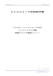
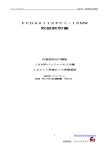
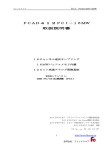
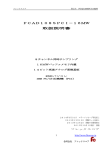
20612 IC core section
9/24/01
12:14 PM
Page 1
™
MODULAR INTERCHANGEABLE
CORE SYSTEM
20612 IC core section
9/24/01
TM
12:14 PM
Page 2
INTERCHANGEABLE CORE
TM
INTERCHANGEABLE CORE
Mortise and rim cylinder housings are a component of Arrow’s total interchangeable core offering. These
housings operate in either Arrow or competitive manufacturer’s products and are compatible with cores
manufactured by a wide range of companies. Mortise housings feature “screw on cams,” ideal for flexible
inventory and simple field service.
RIM CYLINDER HOUSINGS:
MORTISE CYLINDER HOUSINGS:
CAT NO.
APPLICATION
Body: Brass, 1-5/32" diameter
Finishes: 3, 4, 10, 10B, 26, 26D
Furnished with: Cam (specify) and cylinder collar 16-113A, less
core.
C16RCR-16
6 pin only
C16RCR-27
6 or 7 pin
C16RCR-16D
6 pin only, drill resistant
C16RCR-27D
6 or 7 pin, drill resistant
CAT NO.
LENGTH “A”
APPLICATION
C16CR-16
1 1/8"
6 pin only
C16CR-27
1 1/4"
*6 or 7 pin
Body: Brass 1-5/32" diameter
Finishes: 3, 4, 10, 10B, 26, 26D
Furnished with: Blackplate, cylinder collar 16RC-113,
2 screws, 1-3/4" door tailpiece #16RCR-44, less core
CYLINDER COLLARS:
SPACER RINGS:
I.C. Mortise Cylinder Collar 16-113A
I.C. Rim Cylinder Collar
16RC-113
(Standard for 16CR-16, 16CR-27, 16CRH-26)
C16CR-16D
1 1/8"
6 pin only, drill resistant
C16CR-27D
1 1/4"
*6 or 7 pin, drill resistant
C16CRT-16
1 1/8"
6 pin only, tapered
C16CRT-27
1 1/8"
*6 or 7 pin, tapered
C16CRT-16D
1 1/8"
6 pin only, tapered, drill
resistant
C16CRT-27D
1 1/8"
*6 or 7 pin, tapered, drill
resistant
C16CRH-26
1 5/16"
6 pin only, hotel function
Part No.
Description
C16CRH-26D
1 5/16"
6 pin only, hotel function,
drill resistant
A) 3-48 x 3/16
Cam Set Crew
B) C16CR-122
Washer
C) Cam
Specify
D) C16CR-121A-1
Adapter Assembly – 6 pin
E) C16CR-121A
Adapter Assembly – 7 pin
“A”
(Standard for C16RCR-16, C16RCR-27)
Note: With the exception of hotel housing, all cylinder
housings utilize screw on cams. Please specify cam
required, if no cam is specified, Arrow will supply 001
cam. Cam is field changeable.
001
002
003
004
APPLICATION
12, 22, 23, 24, 32(i/s), 33
11, 13, 16, 19, 20, 31, 34, 41, 42, 44
32(o/s)
16CR-123-2
1/4" Thick
16CR-123-3
3/8" Thick
MORTISE HOUSINGS–MISC. PARTS:
16CR-27D,001 cam shown
*These housings are pre-set at the factory to accept 6 pin
cores. Simple change of adapter assembly for 7 pin
cores. This is required for Plus/HS cores only.
CAM
16CR-123-1
1/8" Thick
D
E
USE FOR 7 PIN
C
B
A
CAM
005
006
AR18
APPLICATION
17
Schlage
Adams Rite
RIM HOUSINGS–MISC. PARTS:
Part No.
Description
A) 16RCR-121A-1
Cam Assembly – 6 pin
B) C16RCR-121A
Cam Assembly – 7 pin
C) 16RCR-44
Cam Bar (tailpiece)
D) 16RCR-125
Curved Spring Washer
E) 961CR-117
Yoke-Cam Bar
F) 4-40x1/4
Self-Tapping Screw
B
A
USE FOR 7 PIN
C
D
N Series, Exit Device, Alarms
E
F
Ordering example: 16CR-27Dx001– 6 or 7 pin housing, 001 cam
2
3
20612 IC core section
9/24/01
12:15 PM
Page 4
™
TM
TM
Incorporating the main elements of the interchangeable core concept, ChoICe™ offers a variety of features and
functions, making it the ideal core for a wide range of users. Patented technology, precision manufacturing and
unmatched flexibility are value added components never before seen in interchangeable core. ChoICe™ Base is
our standard level of product. Available in Arrow and competitive keyways, Base is capable of all levels of keying
for new or existing key systems. With an option to have drill resistant pins in the front, plug and shell, ChoICe™
Base offers convenience as well as a higher level of security.
CAT. NO.
Description
C6S
6 pin core, combinated with two
cut change keys
C7S
7 pin core, combinated with two
cut change keys
C6D
6 pin core, drill resistant, combinated with two cut change keys
C7D
7 pin core, drill resistant, combinated with two cut change keys
™
• Modular Interchangeable Core System,
U.S. Patent #6,079,240
• ChoICe™ 6 pin and drill resistant shown
• Also available 7 pin
A.
B.
C.
D.
E.
F.
G.
H.
Plug – C65-102
Locking Tab – C6S-115
Shell – C65-101
Bottom Pin – Standard
Top Pin – Standard
Spring
Cap
Retaining Ring –
C7S-121
I. Front – C7A-112
G
F
E
* M. Plug assy.,
w/hardened pins – C6D-102A
* N. Shell assy.,
w/hardened pins – C6D-101A
O. Stainless bottom pin, for
1st 2 chambers
P. Stainless top pin, for
1st 2 chambers
* Q. Hardened pin and front assy –
C7A-112A
D
H
*Pins inserted at factory only.
B
Note:
• Arrow IC or ID keyway standard
• For uncombinated cores – suffix “UC” to catalog number
(ex: C6S-UCX keyway)
• Available in competitive keyways:
AB, BB, CB, DB, EB, FB, GB, HB, JB, KB, LB, MB, QB
I
G
F
E
P
D
N
O
CAT NO.
Description
C6Sxred
6 pin construction core
C7Sxred
7 pin construction core
PL725PA
Plastic actuator for
construction phase
ChoICe Base
H
M
B
Q
Arrow keyways: 1C, 1D (standard), and restricted keyways
(consult factory for availability).
Competitive keyways: A, B, C, D, E, F, G, H, J, K, L, M, Q.
Part Numbers:
CH x Keyway – 6 or 7 pin blank.
CHP x Keyway – 6 or 7 pin blank, plain bow.
1C
ChoICe™
DUPLICATION PROHIBITED
Keyways:
ChoICe Base DR
1C
1D
AB
BB
CB
DB
EB
FB
GB
4
HB
JB
KB
LB
MB
QB
Consult service manual for 7 pin cores
5
20612 IC core section
9/24/01
TM
12:15 PM
Page 6
™
TM
Incorporating the ChoICe™ technology, the Flex concept combines flexibility and integrity. The system employs a
unique core security feature and patented key design. The security feature being a pin assembly which runs
through the center of the keyway preventing standard IC keys from entering the core. Only the patented Flex key
can operate these cores. Flexcore can be used with standard cores to form a dual level security system. Making it
ideal for schools, universities, hospitals, sports facilities, and institutions where key control is an issue. Adding drill
resistant pins in the front, plug and shell increases the level of security offered by ChoICe™ Flex.
CAT NO.
Description
C6FS
6 pin combinated core, with two
cut change keys
C7FS
7 pin combinated core, with two
cut change keys
C6FD
6 pin combinated core, drill
resistant, with two cut
change keys
C7FD
7 pin combinated core, drill
resistant, with two cut
change keys
™
• Modular Interchangeable Core System,
US Patent #5,778,712, #6,079,240
• ChoICe™ Flex 6 pin and drill resistant shown
• Also available 7 pin
B.
C.
D.
E.
F.
G.
I.
T.
U.
V.
Y.
Locking tab
Shell
Bottom pin – standard
Top pin – standard
Spring
Cap Front
Front – C7A-112
Plug
Retainer washer
Flex Pin
Pin holder washer
G
F
E
N. Shell assy,
w/hardened pins
O. Stainless bottom pin,
for 1st 2 chambers
P. Stainless top pin,
for 1st 2 chambers
Q. Hardened pin and
front assy
X. Plug assy,
w/hardened pins
Note: Flex components are not available. Core sold as complete assembly only.
Y
D
U
C
V
B
I
T
G
F
Note: For uncombinated cores – suffix “UC” to catalog number
(no keys supplied)
EX: C6FS-UCX Keyway
Flex keyways: 51, 52, 53, 54, 61, 64, 81, 83, 84, 91
(All keyways are factory assigned)
Flex keyways available with ChoICe™ Base.
E
P
D
Y
O
N
U
DUALEVEL MASTERKEYING CAPABILITIES:
Arrow Keyways: 51, 52, 53, 54, 61, 64, 81, 83, 84, 91.
Part Numbers:
CHX x Keyway – 6 or 7 pin blank, with hole through blade of key.
CH x Keyway – 6 or 7 pin blank, without hole.
ChoICe Flex
V
The unique pin assembly runs through the center of the core keyway preventing standard I.C. core keys from entering the lock
cylinder. Only the patented Flexcore key can operate locks with
the Flexcore cylinder. Flexcore can be used with standard interchangeable cores to form a dual level security system.
X
B
Q
S
PAT.
W09603562
ChoICe™ Flex
DUPLICATION PROHIBITED
■ Maintenance (A, B, C, D, E)
■ Supervisor A (A, B, D)
■ Supervisor B (A, C, E)
■ General Manager (All doors)†
ChoICe Flex DR
† Door “F” uses Flexcore within masterkey system.
Consult service manual for 7 pin cores
6
7
20612 IC core section
9/24/01
12:15 PM
Page 8
™
TM
™
TM
Another patented product in the ChoICe™ family of cores. Utilizing the ChoICe™ design concept, Plus cores contain a mechanism built into the plug and shell that works in conjunction with a special groove machined in the
key. The patented Plus key will operate both cores with and without the mechanism, however, a non-Plus key will
not operate a Plus core. The addition of drill resistant pins in the front, plug and shell supplements the patented
system and offers resistance to physical attack. Plus is perfect for facilities looking to expand on an existing key
system, increase the level of protection and control, while at the same time, maintaining the integrity of the
records and keyways from an existing phase(s).
CAT NO.
Description
CP6S
6 pin core, combinated, with
two cut change keys
CP7S
7 pin core, combinated, with
two cut change keys
CP6D
6 pin core, drill resistant, combinated, with two cut change keys
CP7D
7 pin core, drill resistant, combinated, with two cut change keys
• Modular Interchangeable Core System,
US Patent #6,079,240, and Patent Pending
• ChoICe™ Plus 6 pin and drill resistant shown
• Also available 7 pin
G
B. Locking tab – C6S-115
D. Bottom pin – standard
E. Top pin – standard
F. Spring
G. Cap
H. Retaining ring –
C7S-121
I. Front – C7A-112
O. Stainless bottom pin, for
1st 2 chambers
P. Stainless top pin, for
1st 2 chambers
* Q. Hardened pin and front
assy – C7A-112A
AI. Plus plug assembly
**AJ. Locking pin
AK. Locking spring
**AL. Cam assembly
**AM. Activating pin
AN. Plus shell – CP6-101
**AO. Pivot
*AR. Plus plug assy, w/hardened
pins – CP6D-102A
*AS. Plus shell assy, w/hardened
pins – CP6D-101A
AL
* Pins inserted at factory.
** Parts not sold separately.
F
E
D
AI
AN
AM
AJ
H
B
I
Note: Arrow IC or ID keyway Standard
For uncombinated cores: suffix “UC” to catalog number
(ex: CP6D-UCX keyway)
Available in Competitive keyways: AB, BB, CB, DB, EB, FB, GB,
HB, JB, KB, LB, MB, QB.
G
AK
F
P
O
Arrow keyways: 1C, 1D (standard), and restricted
keyways–consult factory for availability.
Competitive keyways: A, B, C, D, E, F, G, H, J, K, L, M, Q.
E
AO
Part Numbers:
CPS x Keyway – 6 or 7 pin, Plus keyblank.
D
AS
AR
ChoICe Plus
AL
AM
AJ
B
Q
AK
1C
ChoICe™
DUPLICATION PROHIBITED
AO
Keyways:
ChoICe Plus DR
1C
1D
AB
BB
CB
DB
EB
FB
GB
8
HB
JB
KB
LB
MB
QB
Consult service manual for 7 pin cores
9
20612 IC core section
9/24/01
12:15 PM
Page 10
™
TM
™
TM
Offering the highest degree of key control and security, ChoICe™ HS and HSD blend design with function. The
design process allows for a second locking mechanism to be incorporated, the side bar. When hardened pins are
added, the core meets and exceeds the requirements of UL437 for pick and drill resistance.
CAT NO.
Description
CH7S
7 pin core, combinated, with 2
cut change keys.
CH7D
7 pin core, drill resistant, combinated, with 2 cut change keys.
• Modular Interchangeable Core System,
U.S. Patent #6,079,240, one Patent Pending
• ChoICe™ HS 7 pin and ChoICe™ HSD 7 pin shown
• Available 7 pin only, standard or drill resistant
D.
E.
F.
G.
H.
I.
K.
O.
Bottom pin
Top pin
Spring
Cap
Retaining ring – CS7-121
Front – C7A-112
Locking tab – C7S-115
Stainless bottom pin,
for 1st 2 chambers
P. Stainless top pin,
for 1st 2 chambers
* Q. Hardened pin
and front assy. – C7A-112A
AA. Plug – CH7S-102
Note: For uncombinated cores: Suffix “UC” to catalog number
(ex: CH7S-UC) plus assigned sidebar code.
For unassembled cores: Suffix “LS” to catalog number
(ex: CH7S-UCxLS) – you will receive an uncombinated core, less
sidebar. Combinated cores are not supplied less sidebar.
G
F
AB.
AC.
AD.
AE.
AF.
AG.
Shell – CH7S-101
Side pin spring
Side pin
Side bar spring
Side bar
HSD plug assy.,
w/hardened pins –
CH7D-102A
* AH. HSD shell assy.,
w/hardened pins –
CH7D-101A
E
D
AB
H
*Parts sold as complete assembly only
K
G
I
AA
F
E
AE
D
P
AF
AH
O
Arrow keyways: 40
AC
Part Numbers:
CHHS x Keyway x Sidebar– ID.
AD
ChoICe HS
H
AG
K
Q
40
AF
PAT.
PEND.
ChoICe™ HS
DUPLICATION PROHIBITED
AE
AC
AD
ChoICe HSD
10
11
20612 IC core section
9/24/01
TM
12:15 PM
Page 12
TAILPIECES
TM
Because of the location of the ChoICe™ Plus activating mechanism, and the HS sidebar, all tailpieces require one shorter leg. Old style tailpieces will operate other levels of ChoICe™.
H SERIES KNOB:
H SERIES KNOB:
For all functions except 15 and 19 functions
For 19 function only
CH -66
H6
6 PINS
H69
H7
6 PINS
7 PINS
CH6-44
S SERIES KNOB:
For all functions except 15 and 19 functions
For 19 function only
CH -66
6 PINS
S7
S69
7 PINS
SSCH6-44
SSCH7-44
CH- 66
6 PINS
7 PINS
SSCH69-44
SSCH79-44
For 19 function only, and all OverDrive functions.
6 PINS
L69
7 PINS
CL6-44
6 PINS
CL7-44
CL69-44
Follow disassembly directions in reverse.
Remove retaining ring from back of core.
Plug will slide out from shell.
Slide front plate off (down).
Remove locking tab from shell.
Tip: Hold shell upside down. From front side of shell, insert
locking tab through window of shell, fingers of locking tab will
then engage with slots on shell.
1
2
3
4
S79
For all functions except 15 and 19 functions
L7
1.
2.
3.
4.
CH79-44
Q SERIES LEVER HANDLE:
CH -66
ASSEMBLY:
H79
M, W, Q SERIES LEVER HANDLE:
L6
DISASSEMBLE:
7 PINS
CH69-44
CH7-44
S SERIES KNOB:
S6
CH -66
DISASSEMBLY AND ASSEMBLY OF CORE
CH- 66
L79
7 PINS
CL79-44
M SERIES KNOB:
M6
6 PINS
CM6-44
Note: When replacing retaining ring, flat should be on bottom, with opening
facing toward locking tab.
M7
7 PINS
CM7-44
12
13
20612 IC core section
9/24/01
TM
12:15 PM
Page 14
SERVICE TOOLS
TM
TOOL:
USES:
MISCELLANEOUS SERVICE ITEMS:
Capping Block
This is used to align the core pin
chambers for the Hand
Capping Pin.
Part No.
Description
RB100-RB109
Bottom Pins
RM102-RM119
Top Pins
100CR-107
Springs
100CR-111
Barrel Caps
*SSRB100-109
Stainless Steel Bottom Pins
*SSRM102-119
Stainless Steel Top Pins
Core Capping Press
IC221: 1 Ton IC Press–Self Capping
IC222: Decoding Block
Typically used for high volume
applications. Will cap up to 7
pin chambers at one time.
Cylinder & Key
Stamping Fixture
This is used to stamp keys and
cores. Cores can be stamped
either on the face or on the side.
Decoding Block
“The Block” offers an efficient
method for decoding interchangeable core cylinders to
determine the control key code
or to find a lost operating key for
a core.
P
TO
* Suggested for use in first two chambers of drill resistant cores
IC223: Dual Purpose Capping Block
IC230: I.C. Mortise Cylinder
Installation Tool
0
15
Dumping Block
A specialized block used to
dump and retain pins and
springs from various cores.
• Cores are combinated (pinned) in the same manner as most Best® style cores.
• Pin stack totals for standard A2 system remains 23.
• Best® style key punch machine and pins will operate with ChoICe™ keys and cores.
• ChoICe™ cores will operate in IC products of other manufacturers (Tailpiece modification will be required for Plus and HS/HSD).
• Keyways for Base and Plus levels are compatible with similar existing keyways.
0
14
IC231: I.C. Mortise Cylinder
Housing Assembly Tool
IC235: Ejector Pin
1C237/IC238:
50 Capping Strips (200 Cores)
250 capping strips (1000 Cores)
IC240: Punch Machine
Ejector Pin
The Ejector Pin is used to
remove unwanted pins from
each pin chamber.
Hand Capping Pin
This is used to cap one pin
chamber at a time.
I.C. Keying Kit
This kit contains all of the pins
and springs needed to combinate a core. A different kit is
needed for each I.C. system, i.e.,
(A/2, A/3 or A/4).
Key Combinator
This is used to cut keys by code
or additional keys.
Key Gauge
This is used to find the cuts on a
key in order to duplicate it.
Mortise Cylinder
Installation Tool
This is used as a handle to
install mortise cylinders into a
mortise lock housing.
Punch Machine
This is used for cutting interchangeable core keys, with a
vice change for cutting ChoICe™
flex keys.
IC234: Duo Block
IC236: Combinating Try
IC239: Waffle Tray
IC281: Pin Shear Tool
Note: Most tools are also available from A-1
Manufacturing company.
14
15
20612 IC core section
9/24/01
12:15 PM
Page 16
For more information regarding Arrow’s complete architectural product
offering, contact your Authorized Distributor or Sales Representative.
www.arrowlock.com
ARROW USA: 10300 Foster Avenue • Brooklyn, NY 11236
Phone: (718) 257-4700 • (800) 233-0478 • Fax: (718) 649-9097
ARROW CANADA: 3475 14th Avenue • Markham, Ontario L3R OH4
Phone: (905) 940-2040 • Fax: (905) 940-3242
An ASSA ABLOY Group company
ASSA ABLOY
IC 08/01