1
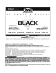
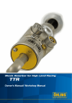
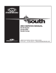
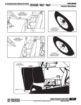
2001 X-VERT SERVICE MANUAL
AMERICAN MADE MANITOU SUSPENSION
CONGRATULATIONS ON CHOOSING THE LATEST IN SUSPENSION TECHNOLOGY AVAILABLE. 2001 X-VERT
FORKS USE MANITOUS PATENTED TPC PLUS (TWIN PISTON CHAMBER) SYSTEM THAT SURPASSES ALL
OTHER TYPES OF OIL DAMPED SYSTEMS IN PERFORMANCE AND DURABILITY. X-VERT FORKS ALSO USE
MANITOUS QUICK AND EASY MICROLUBE SYSTEM, WHICH ALLOWS YOU TO LUBRICATE THE FORK VIA
AN EXTERNAL FITTING ON THE BACK OF THE FORK. ALL MANITOU FORKS COMES EQUIPPED WITH
74MM POST-STYLE DISC BRAKE MOUNTS. THE X-VERT CARBON AND SUPERNOVA USE A 20MM OVERSIZE
THROUGH-AXLE, WHICH IS COMPATIBLE WITH STANDARD DH HUBS.
Your X-Vert fork is fully assembled and ready to be installed onto your bicycle. It comes equipped
with a 1 1/8-inch threadless steerer tube, is available with a V-brake-style hanger-less arch, or
there’s optional attachable cable hanger which is available through your dealer. Manitou does not
recommend retrofitting dual crown forks to older bicycle frames or frames not specially built for
dual crown forks. Dual crown forks may put greater stress on older frames, so you should contact
the frame manufacturer before installing this style of fork on your bike.
2001 X-VERT FORK LINE
X-VERT
105MM TRAVEL/COIL SPRING/TPC PLUS DAMPING/SINGLE CROWN
X-VERT SUPER
105MM TRAVEL/COIL SPRING/TPC PLUS DAMPING/SINGLE MRD HOLLOW CROWN
X-VERT AIR
105MM TRAVEL/AIR/COIL SPRING/TPC PLUS DAMPLING/SINGLE MRD HOLLOW CROWN
X-VERT SUPERNOVA
120MM TRAVEL/COIL SPRING/TPC PLUS DAMPING/SINGLE MRD HOLLOW CROWN/20MM THRU AXLE
X-VERT CARBON
180MM TRAVEL/COIL SPRING/TPC PLUS DAMPING/DUAL CROWN/20MM THRU AXLE
X-VERT DC
120MM TRAVEL/COIL SPRING/TPC PLUS DAMPING/DUAL CROWN
One last note. If you lose this manual, or want to take a look at the X-Vert Service Manual or MRD
Tuning Manual, head straight for the web at www.answerproducts.com or call (661) 257-4411 and
ask for customer service.
GENERAL WARNING: Bicycling is a hazardous activity that requires that the rider stay in control
of his or her bicycle at all times. Reading this manual entirely and properly maintaining your
bicycle and suspension fork will reduce the possibility of injury or possible death. Prior to riding
your bicycle, you should inspect your suspension fork to ensure that no damage has occurred
during the course of riding. Do not ride your bicycle if the fork shows any signs of bending,
cracking, leaking, or if it is missing any of the originally supplied components. Any fall from
your bicycle can result in serious injury or even death. Following these instructions can help you
reduce the risk of being injured.
If you are a moderate or aggressive off-road rider, or ride at least three times a week over
rough terrain, Answer recommends returning your suspension fork every 2 years for a thorough
inspection and update. Take your fork to a Manitou authorized dealer who can arrange for shipment to Answer Products, or you may call Answer at (661) 257-4411 to have your fork shipped
directly.
IMPORTANT: The X-VERT fork is an off-road fork, and as such, does not come with proper reflectors for on road use. Have your dealer or mechanic install proper reflectors to meet the
Consumer Product Safety Commission’s (C.P.S.C.) Requirements for Bicycles if the fork is going
to be used on public roads at any time. If you have questions regarding C.P.S.C. Standards or
would like to purchase reflector bracket kit (Part Number 85-3674) contact your dealer.
1 Never remove or have the steerer tube or stanchions (inner legs) removed from the crown. The
steerer tube and stanchions are press-fit into the crown at the factory. Pressing them out will
permanently damage the crown, steerer tube, and stanchions beyond repair and thus, render
them unsafe for any further use.
2 Never attempt to thread a threadless steerer tube. Machining threads will weaken the steerer
tube and cause an unsafe condition. The only safe alternative is to obtain the proper
crown/steererer from your dealer.
3 Any other alterations or modifications to your fork should be considered unsafe. Please contact
Answer Products technical support at (661) 257-4411 for safety information prior to modifying
your fork in any way.
4 Do not use your Manitou fork if any part appears to be broken, bent, cracked, or damaged in
any way. Contact your dealer or Answer Products technical support, (661) 257-4411, if you
have any questions concerning the integrity, condition, or safe operation of your fork.
5 Answer Products recommends that you periodically inspect your fork for wear and damage.
Inspect the crown, stanchions, and outer leg dropout and brake arch areas for cracks or
damage. Before every ride, check to ensure the proper preload exists.
WARRANTY INFORMATION
Any Answer Products fork found by the factory to be defective in materials and/or workmanship
within one year from the date of purchase will be repaired or replaced at the option of the
manufacturer, free of charge, when received at the factory, freight prepaid. This warranty does not
cover breakage, bending, or damage that may result from crashes or falls. This warranty does not
cover any fork that has been subject to misuse or whose serial number has been altered, defaced or
removed. This warranty does not cover paint damage. Any modifications made by the user will
render the warranty null and void. This warranty is expressly in lieu of all other warranties, and any
implied are limited in duration to the same duration as the expressed warranty herein. Answer
Products shall not be liable for any incidental or consequential damages.
If for any reason warranty work is necessary, return the fork to the place of purchase. In the USA,
dealers should call Answer Products for a return authorization number (RA#). At that time,
instructions for repair, return, or replacement shall be given. Customers in countries other than USA
should contact their dealer or local distributor.
INSTALLATION INSTRUCTIONS
Ensure that the proper steerer tube has been delivered on your X-VERT first. The steerer tube may
need to be cut to length to fit your bicycle head tube. If you are not familiar with this procedure,
or do not have the proper tools to cut the steerer tube, it is recommended that you seek a dealer
with a qualified bicycle mechanic to perform installation.
WARNING: The steerer tube and stanchions (inner legs) are a one-time precision press fit at the
factory and cannot be removed from the crown. Replacement of the entire crown/steererer
assembly must be done to change steerer tube lengths or diameters. Removing and replacing
the steerer tube or stanchions will result in an unsafe condition and should never be done.
.1.
Race Installation
Einbau des Steuersatzringes
Instalación del anillo de rodadura
Installation du jeu de direction
Montaggio dell’anello della testa
Installatie van loopring
Instalação do canalete
CROWN RACE
GABELBRÜCKENSTEUERSATZRING
ANILLO DE RODADURA
CONE DE JEU DE DIRECTION
ANELLO DELLA TESTA
KROONLOOPRING
CANALETE DA COROA
.2.
Axle and hub installation
Montaggio dell’assale e
Einbau der Achse und Nabe del mozzo
Instalación del eje y cubo
Installatie van as en naaf
Installation de l’axe et
Instalação do eixo e do
du moyeu
cubo
RIGHT PINCH BOLTS
RECHTE KLEMMSCHRAUBEN
PERNOS DE
PRESIÓN DERECHOS
BOULONS À SERRAGE
DU CÔTÉ DROIT
BULLONI DI SERRAGGIO
DI DESTRA
RECHTER KLEMBOUTEN
PARAFUSOS DIREITOS
DE APERTO
LEFT PINCH BOLTS
LINKE KLEMMSCHRAUBEN
PERNOS DE PRESIÓN
IZQUIERDOS
BOULONS À SERRAGE DU
CÔTÉ GAUCHE
.3.
Tire clearance
Reifenabstand
Espacio libre de la cubierta
Distance arceau/pneu
Spazio libero del pneumatico
Bandspeling
Folga do pneu
AXLE
ACHSE
EJE
AXE
ASSALE
AS
EIXO
BULLONI DI SERRAGGIO
DI SINISTRA
LINKER KLEMBOUTEN
PARAFUSOS ESQUERDOS
DE APERTO
FORK MODEL
GABELMODELL
MODELO DE HORQUILLA
MODÈLE DE FOURCHE
MODELLO DI FORCELLA
VORKMODEL
MODELO DO GARFO
MINIMUM CLEARANCE
MINDESTABSTAND
ESPACIO LIBRE MÍNIMO
JEU MINIMUM
SPAZIO LIBERO MINIMO
MINIMUMSPELING
FOLGA MÍNIMA
105 mm travel forks
120 mm travel forks
180 mm travel forks
4.14” (105 mm)
4.73” (120 mm)
7.10” (180 mm)
Gabel mit 105 mm Auslenkung
Gabel mit 120 mm Auslenkung
Gabel mit 180 mm Auslenkung
105 mm
120 mm
180 mm
Horquillas con recorrido de 105 mm
Horquillas con recorrido de 120 mm
Horquillas con recorrido de 180 mm
105 mm
120 mm
180 mm
Fourches ayant une course de 105 mm
Fourches ayant une course de 120 mm
Fourches ayant une course de 180 mm
105 mm
120 mm
180 mm
Forcelle con corsa da 105 mm
Forcelle con corsa da 120 mm
Forcelle con corsa da 180 mm
105 mm
120 mm
180 mm
Loop van 105 mm
Loop van 120 mm
Loop van 180 mm
105 mm
120 mm
180 mm
Curso de 105 mm
Curso de 120 mm
Curso de 180 mm
105 mm
120 mm
180 mm
Fork Installation
1 Remove the old fork from your bicycle.
2 Measure and cut the steerer tube to fit your bicycle head tube. You can use your old fork as a
guide to how long you should cut the steerer tube.
3 Remove the headset crown race from the old fork and press onto X-VERT steerer until the race
is seated over the crown
4 Clean and grease the headset bearings and races.
5 Install the lower bearings (if applicable) on fork crown race.
6 Insert the steerer tube into the head tube of the frame.
7 Install the upper bearings, stem spacers, and stem.
8 Install the stem cap and bolt. Tighten the bolt to headset manufacturer’s specifications.
9 Install the handlebars and the torque stem pinch screws or stem clamping system to
manufacturer’s specifications.
10 Install the brakes and adjust per the manufacturer’s instructions.
11 Position the X-VERT CARBON (dual crown fork) steerering stop bumpers to prevent frame
damage.
12 For all X-VERTS except X-VERT CARBON and X-VERT SUPERNOVA, adjust the front wheel quick
release to clear the 0.275 (7MM) thick secondary catch dropout. The quick release must be
tightened after it is properly seated into the dropout counter bores to manufacturer’s
specifications. Ensure that there is adequate thread engagement (4 or more threads with the
release adjusted to lock).
13 For the X-VERT CARBON and X-VERT SUPERNOVA, lightly pinch the thread axle sleeve in the left
dropout. Install the through axle and hub. Tighten the axle until it bottoms 60 to 90 in-lbs.
(6.8-5.6Nm). Push the fork up and down to find the center position and torque the right
dropout pinch bolts to 30 to 50 in-lbs. (3.4-5.6 NM).
14 Install the brake cable per manufacturer’s instructions:
Note: 2001 X-VERT, X-VERT AIR, X-VERT DC, AND X-VERT SUPER forks are equipped with a secondary
catch dropout, The X-VERT CARBON and X-VERT SUPERNOVA forks are equipped with a oversize
20mm through axles that are compatible with standard DH hubs.
WARNING: When installing wheel or any new tire check the minimum tire clearance. Measure
from the highest point on the tire to the bottom of the crown. The minimum clearance allowed
for 105MM travel fork models is 4.25"(108.0MM), for 120MM travel fork models is 4.84" (123MM)
and for 180MM travel fork models is 7.20" (183MM). Any less clearance can result in accident
resulting in serious injury or death. Figure 2
SPARE PARTS:
Spare parts can be ordered through your local dealer. If you have any problems that you cannot
resolve with your dealer, you may call Answer Products technical/warranty service department at
(661) 257-4411, 8:00 AM to 5:00 PM, Pacific Standard time, Monday through Friday. In addition,
helpful information can be found on the Answer Products website at www.answerproducts.com
where you may download manuals and e-mail us for technical support.
DESCRIPTION
PART NUMBER
2001 X-VERT CARBON X-FIRM RIDE KIT
85-9236
2001 X-VERT SUPERNOVA X-FIRM RIDE KIT
85-9235
2001 X-VERT SUPERNOVA BLACK OUTER ASSEMBLY
85-9234
2001 X-VERT SUPERNOVA FIRM RIDE KIT
85-9229
2001 X-VERT CARBON SOFT RIDE KIT
85-9228
2001 X-VERT SUPERNOVA SOFT RIDE KIT
85-9227
2001 X-VERT AIR X-FIRM RIDE KIT
85-9226
2001 X-VERT & X-VERT SUPER X-FIRM RIDE KIT
85-9225
2001 X-VERT AIR ALLOY STEERER/LEG ASSEMBLY
85-9215
2001 X-VERT SUPER ALLOY STEERER/LEG ASSEMBLY
85-9214
2001 X-VERT AIR FIRM RIDE KIT
85-9190
2001 X-VERT AIR SOFT RIDE KIT
85-9189
2001 X-VERT X-VERT, X-VERT AIR & X-VERT SUPER RED OUTER ASSEMBLY
85-9144
2001 X-VERT & X-VERT SUPER SOFT RIDE KIT
85-9100
2001 X-VERT & X-VERT SUPER FIRM RIDE KIT
85-9099
2001 X-VERT STEERER/LEG ASSEMBLY
85-9096
2001 X-VERT X-VERT, X-VERT AIR & X-VERT SUPER BLUE OUTER ASSEMBLY
85-9093
2001 X-VERT X-VERT, X-VERT AIR & X-VERT SUPER BLACK OUTER ASSEMBLY
85-9091
2001 X-VERT AIR & X-VERT SUPER REBOUND DAMPING ASSEMBLY
85-9084
2001 X-VERT, X-VERT AIR, & X-VERT SUPER COMPRESSION DAMPING ASSEMBLY
85-9084
2000 X-VERT CARBON FIRM RIDE KIT
85-9080
2001 X-VERT CARBON BLACK OUTER ASSEMBLY
85-9077
2001 X-VERT CARBON STICKER KIT
85-9076
2001 X-VERT CARBON COMPRESSION DAMPING ASSEMBLY
85-9075
2001 X-VERT CARBON REBOUND DAMPING ASSEMBLY
85-9074
2001 X-VERT, X-VERT SUPER, X-VERT SUPERNOVA &
X-VERT CARBON PRELOAD ADJUSTER ASSEMBLY
85-9073
2001 X-VERT SUPERNOVA RED STICKER KIT
85-4139
2001 X-VERT SUPER RED SITCKER KIT
85-4137
2001 X-VERT AIR RED STICKER KIT
85-4136
2001 X-VERT AIR BLUE/BLACK STICKER KIT
85-4135
2001 X-VERT RED STICKER KIT
85-4134
2001 X-VERT BLACK STICKER KIT
85-4133
X-VERT AIR FORK PUMP
85-4069
2001 X-VERT SUPERNOVA & X-VERT CARBON BUSHING & SEAL KIT
85-4057
2001 X-VERT, X-VERT AIR, & X-VERT SUPER BUSHING & SEAL KIT
85-3828
2001 MRD TUNING MANUAL
85-3696
2001 X-VERT AIR CAP/PISTON KIT
85-3033
2001 X-VERT SUPERNOVA COMPRESSION DAMPING ASSEMBLY
85-3031
2001 X-VERT SUPERNOVA REBOUND DAMPING ASSEMBLY
85-3029
2001 X-VERT REBOUND DAMPING ASSEMBLY
85-3026
2001 X-VERT SUPERNOVA ALLOY STEERER/LEG ASSEMBLY
85-3025
PREP M GREASE
85-3010
2001 X-VERT FORK SCHEMATIC
BUSHING & SEAL DETAIL
PAD JELLY BEAN (062586)
SELF TAPPING SCREW (041330)
ADJUSTER KNOB (062503)
FORK BOOT (041544)
PAD ASSEMBLY
(063210)
TOP CAP (062583)
(TORQUE 30-50 INCH-LBS)
(TORQUE 3.5-5.6 N-m)
O-RING 1/4 X 3/8 (040690)
UPPER NEEDLE (062475)
O-RING 5/32 X 9/32 (041130)
DETENT SLEEVE (041527)
DETENT BALL (040689)
UPPER SEAL (062531)
UPPER BUSHING (041503)
O-RING 21.6MM X 2.4MM (040524)
UPPER SHAFT (062474)
PISTON SEAT (062130)
11MM CLAMP SHIM (041170)
15MM SPRING SHIM (041144)
LOWER BUSHING (041504)
21MM SPRING SHIM (041150)
REBOUND PISTON (062562)
SPRING (041152)
BLOW OFF SHIM (041139)
SLIDING PISTON SEAT (062259)
17MM SHIM (041146)
19MM SHIM (041148)
20MM SHIM (041149)
21MM SHIM (041150)
REBOUND PISTON (062562)
PISTON SLIDE SHAFT (062262)
O-RING (041130)
SPRING (062419)
O-RING 5/32" x 9/32" (041130)
ADJUSTER ASSEMBLY (062540)
(TORQUE 30-50 INCH-LBS)
(TORQUE 3.5-5.6 N-m)
RED MCU
(041425)
SHIM (041139)
SPRING (041152)
COMP VALVE NUT (041483)
LOWER NEEDLE (062570)
O-RING (040690)
MCU CONNECTOR
(041237)
CAP SCREW (062566)
CROWN/STEER
SPIROLOX RETAINER (062393)
RED MCU (041425)
SHAFT SEAL (062392)
SPRING CONNECTOR (041377)
END CAP (062580)
(TORQUE 30-50 INCH-LBS)
(TORQUE 3.5-5.6 N-m)
LOWER SHAFT ASSEMBLY
(063200)
O-RING (040673)
110 LB SPRING 5.875" LONG (041890)
VALVE NUT (041483)
CLAMP SHIM (01170)
REBOUND ELASTOMER (041475)
SHIM 15MM (041144)
CUP WASHER (040691)
SHIM 18MM (041147)
REBOUND ELASTOMER
(041475)
SHIM 21MM (041150)
REBOUND PISTON (062562)
.826 X .409 X .005 SHIM (041139)
INNER LEG
(062560)
SPRING (041152)
INNER LEG
(062560)
PISTON SEAT (062130)
LOWER SHAFT (062569)
DETENT BALL
(040689)
COMPRESSION ROD (062568)
DROPOUT SLEEVE (041574)
REBOUND ELASTOMER (041475)
BRAKE POST (040921)
(TORQUE 90-110 IN-LBS)
(TORQUE 10-12 N-m)
END CAP (062255)
(TORQUE 30-50 INCH-LBS)
(TORQUE 3.5-5.6 N-m)
REBOUND ELASTOMER (041475)
CUP WASHER (040691)
REBOUND ELASTOMER (041475)
OUTER LEG/ARCH
ASSEMBLY
DAMPER DROPOUT NUT (041822)
O-RING, DROPOUT NUT (040688)
DAMPER ADJUSTER KNOB
(041408)
GREASE FITTING (062036)
COMPRESSION ROD SCREW (060268)
(TORQUE 10-30 INCH-LBS)
(TORQUE 1.2-3.5 N-m)
PAD ASSEMBLY (062628)
2001 X-VERT SUPERNOVA FORK SCHEMATIC
BUSHING & SEAL DETAIL
PAD JELLY BEAN (062586)
LOWER SHAFT ASSEMBLY
SELF TAPPING SCREW (041330)
ADJUSTER KNOB (062503)
(062613)
VALVE NUT (041483)
TOP CAP (062583)
(TORQUE 30-50 INCH-LBS)
(TORQUE 3.5-5.6 N-m)
CLAMP SHIM (01170)
SPRING SHIM 15MM (041144)
EXCLUDOR (063044)
SPRING SHIM 17MM (041146)
O-RING 1/4 X 3/8 (040690)
SPRING SHIM 18MM (041147)
(2 X) SPRING SHIM 19MM (041148)
UPPER BUSHING (0641503)
LOWER BUSHING (062145)
UPPER NEEDLE (062072)
O-RING 5/32 X 9/32 (041130)
SPRING SHIM 21MM (041150)
LOWER SEAL (062532)
DH PISTON RING (041733)
UPPER SHAFT (063092)
PISTON SPACER (041045)
SPRING (041152)
O-RING 21.6MM X 2.4MM (040524)
DETENT SLEEVE (041527)
DETENT BALL (040689)
REBOUND PISTON (041407)
PISTON SEAT (062130)
13MM CLAMP SHIM (041157)
16MM CLAMP SHIM (041145)
19MM CLAMP SHIM (041149)
21MM CLAMP SHIM (041150)
15MM CLAMP SHIM (041144)
PISTON SEAT (062130)
LOWER SHAFT (062569)
DETENT BALL
(040689)
REBOUND PISTON (062566)
O-RING 5/32" x 9/32" (041130)
SHIM (041139)
LOWER NEEDLE (062570)
O-RING 1/4 X 3/8 (040690)
SPIROLOX RETAINER (062393)
SHAFT SEAL (062392)
SPRING (041152)
PISTON SLIDE SHAFT (062612)
O-RING (041130)
SPRING (062600)
END CAP (062580)
(TORQUE 30-50 INCH-LBS)
(TORQUE 3.5-5.6 N-m)
SLIDING PISTON SEAT (062259)
CROWN/STEER
LEG ASSEMBLY
19MM SHIM (041148)
21MM SHIM (041150)
O-RING (040673)
16MM SHIM (041145)
13MM SHIM (041157)
ELASTOMER
(041475)
REBOUND PISTON (062562)
SHIM (041139)
SPRING (041152)
COMP VALVE NUT (041483)
CAP SCREW (062566)
AXLE INSERT (062741)
AXLE (062738)
END CAP (062255)
(TORQUE 30-50 INCH-LBS)
(TORQUE 3.5-5.6 N-m)
ADJUSTER ASSEMBLY (062540)
(TORQUE 30-50 INCH-LBS)
(TORQUE 3.5-5.6 N-m)
REBOUND ELASTOMER (041462)
M5 X 18MM SHCS
(030405) (X4)
RED MCU (041425)
MCU CONNECTOR (041237)
RED MCU (041425)
CARBON FIBER
LEG ASSEMBLY
DROP COVER (062626)
HAND TIGHTEN
SPRING CONNECTOR (041377)
DROPOUT NUT (061822)
110 LB SPRING 5.875"
LONG (041890)
O-RING (040673)
ADJUSTER KNOB
(041658)
AXLE NUT (062739)
DROP COVER (062627)
HAND TIGHTEN
COMPRESSION ROD SCREW (060268)
(TORQUE 10-30 INCH-LBS)
(TORQUE 1.2-3.5 N-m)
COMPRESSION ROD (062568)
URETHANE REBOUND (041475)
2001 X-VERT SUPER FORK SCHEMATIC
BUSHING & SEAL DETAIL
PAD JELLY BEAN (062586)
SELF TAPPING SCREW (041330)
ADJUSTER KNOB (062503)
FORK BOOT (041544)
TOP CAP (062583)
(TORQUE 30-50 INCH-LBS)
(TORQUE 3.5-5.6 N-m)
PAD ASSEMBLY
(063210)
O-RING 1/4 X 3/8 (040690)
UPPER NEEDLE (062475)
O-RING 5/32 X 9/32 (041130)
UPPER SEAL (062531)
DETENT SLEEVE (041527)
DETENT BALL (040689)
UPPER BUSHING (041503)
O-RING 21.6MM X 2.4MM (040524)
UPPER SHAFT (062474)
PISTON SEAT (062130)
11MM CLAMP SHIM (041170)
LOWER BUSHING (041504)
15MM SPRING SHIM (041144)
21MM SPRING SHIM (041150)
REBOUND PISTON (062562)
SPRING (041152)
BLOW OFF SHIM (041139)
PISTON SLIDE SHAFT (062262)
O-RING (041130)
SPRING (062419)
SLIDING PISTON SEAT (062259)
17MM SHIM (041146)
19MM SHIM (041148)
20MM SHIM (041149)
21MM SHIM (041150)
REBOUND PISTON (062562)
11MM CLAMP SHIM (041170)
SPRING (041152)
O-RING 5/32" x 9/32" (041130)
LOWER NEEDLE (062570)
COMP VALVE NUT (041483)
CAP SCREW (062566)
CROWN/STEER
O-RING (040690)
SPIROLOX RETAINER (062393)
SHAFT SEAL (062392)
END CAP (062580)
(TORQUE 30-50 INCH-LBS)
(TORQUE 3.5-5.6 N-m)
RED MCU
(041425)
MCU CONNECTOR
(041237)
RED MCU (041425)
SPRING CONNECTOR (041377)
LOWER SHAFT ASSEMBLY
(062561)
O-RING (040673)
REBOUND ELASTOMER (041462)
110 LB SPRING 5.875" LONG (041890)
VALVE NUT (041483)
CLAMP SHIM (01170)
CUP WASHER (040691)
REBOUND ELASTOMER
(041475)
ADJUSTER ASSEMBLY (062540)
(TORQUE 30-50 INCH-LBS)
(TORQUE 3.5-5.6 N-m)
SHIM 16MM (041145)
REBOUND PISTON (041407)
.826 X .409 X .005 SHIM (041139)
PISTON SPACER (041045)
SPRING (041152)
RIGHT LEG
(062597)
LEFT LEG (062560)
PISTON SEAT (062130)
LOWER SHAFT (062569)
DETENT BALL
(040689)
TITANIUM BRAKE POST (041396)
(TORQUE 90-110 INCH-LBS)
(TORQUE 10-12 N-m)
COMPRESSION ROD (062568)
DROPOUT SLEEVE
(041574)
REBOUND ELASTOMER (041475)
END CAP (062255)
(TORQUE 30-50 INCH-LBS)
(TORQUE 3.5-5.6 N-m)
REBOUND ELASTOMER (041475)
CUP WASHER (040691)
REBOUND ELASTOMER (041475)
OUTER LEG/ARCH
ASSEMBLY
DAMPER DROPOUT NUT (041822)
O-RING, DROPOUT NUT (040688)
DAMPER ADJUSTER KNOB
(041408)
GREASE FITTING (062036)
COMPRESSION ROD SCREW (060268)
(TORQUE 10-30 INCH-LBS)
(TORQUE 1.2-3.5 N-m)
MAINTENANCE
IMPORTANT: Your X-VERT fork should not be used if any parts appear to be damaged.
Please contact your local dealer or Answer Products for replacement parts.
IMPORTANT: Use of fork boots is required to keep your X-VERT fork performing well and the
warranty in effect. Use of this fork without boots will shorten the life of the fork, decrease the
time between maintenance intervals, reduce the performance and void the warranty. The only
exception is a fork that is sold by Answer from the factory without boots.
Your X-VERT fork requires periodic maintenance, cleaning and
inspection. This is because moisture and contaminants may build up
inside the fork depending on the severity of the riding conditions. To
maintain top performance, it is recommended that the fork be
periodically disassembled, cleaned, dried and re-greased using
Microlube grease ports located on the back of each outer leg.
IMPORTANT: When lubricating the fork with grease through the grease
port, it is important to note the grease is being forced between the
upper and lower bushings. If the area is overfilled the force of the
grease may force the upper bushing and dust seal out. You should only
insert grease to the level at which stiction is no longer felt.
IMPORTANT: Before every ride you should:
1 Ensure that quick release skewers are properly adjusted and tight.
2 Wipe the inner legs clean, lubricate and check the entire fork for any obvious damage.
3 Check headset adjustment.
4 Ensure the front brake cable is properly seated in the cable retainer
& verify proper brake adjustment.
IMPORTANT: Maintaining the proper oil level in your TPC Plus equipped
fork is critical. TPC Plus is located in the right leg of your X-VERT fork.
Not enough oil will allow foaming and reduce the performance. Too
much oil will restrict travel and may cause damage to the system and
MEASURE OIL LEVEL
FROM TOP OF CROWN
create an unsafe riding condition. Finish reading this entire section
prior to altering the oil level.
MAXIMUM
RECOMMENDED
To check the oil level, remove the compression damping assembly
MINIMUM
located in the top of the right leg. Leave the left side spring stack in
place to keep the fork fully extended. Use a tape measure or dip
stick to determine the oil level. It is recommended that you replace
your oil at least once during the season, or twice if it has been contaminated with dirt, mud, or any
other substance. Use SAE 5WT Maxima fork oil or equivalent. Refer to Figure 10 for the
recommended oil level, or for a specific fork models refer to table 2.
OIL LEVEL TABLE: 2
Fork Model
X-Vert
X-Vert Air
X-Vert-Super
X-Vert-Supernova
X-Vert DC
X-Vert-Carbon
Recommended
3.75"(95mm)
3.75"(95mm)
3.75"(95mm)
4.50"(114mm)
8.00"(203mm)
8.00"(203mm)
Maximum
3.50"(89mm)
3.50"(89mm)
3.50"(89mm)
4.25"(108mm)
10.0"(254mm)
7.00"(178mm)
Minimum
4.00"(102mm)
4.00"(102mm)
4.00"(102mm)
4.75"(120mm)
9.00"(229mm)
9.00"(228mm)
GENERAL DISASSEMBLY
NOTE: Your fork does not need to be removed from the bicycle for general disassembly or cleaning.
Furthermore, it is not necessary to disassemble your fork to service the spring stack or to change
the oil height. You may service the spring stack by removing the adjuster assembly as shown in
Figure 12, Step 1.
STEP 1
REMOVE ADJUSTERS
AND FULLY COMPRESS
FORK LEGS TO KEEP
COMPRESSION RODS
FROM TURNING
STEP 2
POP OUT KNOB
REMOVE NUT USE
8MM ALLEN WRENCH
REMOVE
COMPRESSION
ROD SCREW,
USE 5MM
ALLEN WRENCH
PULL DOWN TO REMOVE
OUTER FORK LEG UNIT
Removal of outer leg, Figure 11:
1 Use a 4MM Allen wrench to remove the M5 lower compression rod screw from the left leg side.
2 Pop out the damping adjuster knob from the right side (a small screwdriver may be helpful).
Use an 8MM allen wrench to remove the dropout nut (it may be helpful to compress the fork to
prevent the compression rod and damper shaft from turning while removing these screws).
3 Pull the outer leg assembly off the inner legs and crown assembly.
4 Remove the fork boots.
5 Bushing replacement will require the use of the bushing removal and installation tool available
from Answer Products. It is recommended that the bushings be left installed unless they
absolutely need replacement.
Note: It is not recommended to remove the dust
STEP 1
seal every time the fork is disassembled. The
CONNECTORS MUST BE BETWEEN
seal and bushings may be cleaned and reALL MCU & SPRING
greased in place.
1 Unscrew and remove the spring adjuster
INSPECT MCU & SPRINGS
assembly.
STEP 2
2 Unscrew the end cap from the left inner leg
and pull the compression rod out of the inner
leg.
Lower Shaft Disassembly Figure 13:
B. TIP FORK UPSIDE DOWN TO REMOVE
Note: Lower Shaft removal/disassembly is best
done with the fork removed from the bicycle.
A. REMOVE BOTTOM ELASTOMER,
ELASTOMER, CUP WASHER
Disassembly of the damping assembly is not
AND ELASTOMER.
required unless you want to modify or replace the
shim stack.
1 Unscrew and remove the TPC + compression damping assembly from the top of the right leg
and discard the oil appropriately.
2 Unscrew the end cap and pull the lower shaft assembly out of the inner leg.
3 Remove the bottom out elastomers and capture the 1/8" diameter detent ball.
4 The adjuster needle may be unscrewed and removed from the shaft. However, this is not
recommended.
5 Remove the valve nut to change the shim stack. It is recommended that you write down the
order of the factory specified shim stack and spacers before you begin revalving. Thus, you will
always be able to easily revert to the factory set-up.
6 Unscrew the compression damping adjuster until it stops. Do not remove the shaft from the
cap because the threads are bonded to prevent leaking.
7 Unscrew the button head screw from the bottom of the assembly.
8 Remove the O-ring, floating piston assembly and spring.
9 You may disassemble the floating piston assembly to modify the shim stack. However, it is
recommended that you use the precautions mentioned in the instructions for disassembly of
the lower shaft assembly.
10 Remove either the floating piston shaft or the piston seat following the instructions above for
the lower shaft assembly.
X-VERT
LOWER SHAFT ASSEMBLY
(062563)
X-VERT SUPER
LOWER SHAFT ASSEMBLY
(062561)
VALVE NUT (041483)
CLAMP SHIM (01170)
VALVE NUT (041483)
CLAMP SHIM (01170)
SPRING (041152)
LOWER NEEDLE (062570)
SPIROLOX RETAINER (062393)
WASHER (062413)
SHAFT SEAL (062392)
END CAP (062580)
SHAFT SEAL (062392)
END CAP (062580)
O-RING (040673)
O-RING (040673)
REBOUND ELASTOMER (041462)
CUP WASHER (040691)
REBOUND ELASTOMER
(041462)
REBOUND ELASTOMER (041462)
CUP WASHER (040691)
REBOUND ELASTOMER
(041462)
LOWER SHAFT (062569)
PISTON SPACER (062294)
SPRING (041152)
PISTON SEAT (062130)
O-RING 5/32" x 9/32" (041130)
O-RING (040690)
O-RING (040690)
SPRING SHIM 21MM (041150)
DETENT BALL
(040689)
O-RING (041130)
SPIROLOX RETAINER (062393)
WASHER (062413)
(2 X) SPRING SHIM 11MM (041140)
REBOUND PISTON (062131)
DH PISTON RING (041733)
DETENT BALL
(040689)
LOWER NEEDLE (062570)
LOWER SHAFT (062128)
DETENT BALL
(040689)
LOWER NEEDLE (062570)
O-RING 1/4 X 3/8 (040690)
O-RING 5/32" x 9/32" (041130)
SPIROLOX RETAINER (062393)
WASHER (062413)
SHAFT SEAL (062392)
LOWER NEEDLE (062133)
O-RING 1/4 X 3/8 (040690)
END CAP (062580)
O-RING 15/16" x 1 1/16"
(040673)
REBOUND ELASTOMER
(041462)
SPRING SHIM 17MM (041146)
SPRING SHIM 18MM (041147)
(2 X) SPRING SHIM 19MM (041148)
.826 X .409 X .005 SHIM (041139)
PISTON SPACER (041045)
SPRING (041152)
PISTON SEAT (062130)
LOWER SHAFT (062569)
DETENT BALL
(040689)
SPRING SHIM 16MM (041145)
REBOUND PISTON (062562)
PISTON SEAT (062130)
LOWER SHAFT (062569)
VALVE NUT (041483)
CLAMP SHIM (01170)
SHIM 15MM (041144)
SHIM 18MM (041147)
SHIM 20MM (041149)
SHIM 21MM (041150)
.826 X .409 X .005 SHIM (041139)
SPRING (041152)
O-RING 5/32" x 9/32" (041130)
REBOUND SHIM 17mm (041146)
CLAMP SHIM (01170)
REBOUND PISTON (062562)
REBOUND PISTON (062562)
.826 X .409 X .005 SHIM (041139)
SPIROLOX RETAINER (062393)
WASHER (062413)
SHAFT SEAL (062392)
END CAP (062580)
O-RING (040673)
ELASTOMER
(041462)
X-VERT CARBON
LOWER SHAFT ASSEMBLY
(062509)
VALVE NUT (041483)
SHIM 15MM (041144)
SHIM 18MM (041147)
SHIM 20MM (041149)
SHIM 21MM (041150)
SHIM 15MM (041144)
SHIM 18MM (041147)
SHIM 20MM (041149)
SHIM 21MM (041150)
PISTON SEAT (062130)
X-VERT DC
LOWER SHAFT ASSEMBLY
(062506)
DAMPER INSPECTION
1
2
4
5
6
Inspect the shaft for scratches, wear, or other obvious damage.
Inspect the seal gland and end cap seal grooves for damage.
Inspect shims for permanent bends or damage.
Inspect all other parts for obvious damage, and replace as necessary.
Replace all seals that have been removed.
FORK INSPECTION
1 Inspect the fork boots for obvious damage.
2 Inspect the dust seal for tears, wear, or damage. Replace as needed.
3 Inspect the lower and upper bushing for damage to the Teflon coating. Replace using the
bushing removal and replacement kits if necessary.
4 Inspect all MCU’s & springs for obvious damage. Replace as necessary.
5 Inspect the preload adjuster and connectors. Replace if damaged.
6 Check the outer legs for nicks or deep gouges on the outside and inside. Replace if damaged.
7 Check the inner legs for deep gouges or any other obvious damage. Slight wear resulting in a
color change is not detrimental to the gold anodized surface. Replace the crown/leg assembly
if wear is excessive or if it is damaged.
8 Check inner legs at the bottom of the crown for cracks or for flaking of the anodizing. Replace
crown/leg assembly if cracked or if gold anodize is beginning to flake.
9 Check the crown for cracks. Replace if cracked.
REASSEMBLY
1
2
3
4
5
6
7
8
Install all previously removed O-rings and seals.
Lightly grease all seals with seal grease.
Apply a small amount of blue Loktite to piston seat threads.
First, reassemble shim stack, spacers and piston in exact order they were removed. Next,
thread the valve nut onto the piston seat and torque it to 12 IN-LB (1.2 N-M) max.
Install lower needle gently into shaft, thread until it stops, then back off one turn for initial
adjustment.
Slide shaft assembly through the plastic end cap.
Slide an elastomer onto the shaft followed by the cup spacer. Next, place the detent ball in its
hole and slide another elastomer over it. Note: The X-VERT DC & X-VERT Carbon do not use
the cup washer and 2nd elastomer. Therefore, the first elastomer is used to retain the detent
ball.
Insert into right leg and thread in end cap. Torque 30 IN-LB (3.5N-m) max.
Compression Damping Assembly
1 Install all previously removed O-rings.
2 Apply a small amount of blue Loktite to piston seat threads.
3 Reassemble shim stack, spacers and pistons in exact order they were removed. Next, thread
the valve nut onto the sliding piston assembly. Likewise, thread the sliding piston shaft onto
the piston seat and torque them both to 12 IN-LB (1.2 N-M) max. Then, install an O-ring and
the sliding piston spring onto the sliding piston shaft. Slide the sliding piston assembly onto the
shaft and then slide another O-ring onto the shaft behind the sliding assembly. Finally, screw
the button head cap screw with blue Loktite applied to it into the sliding piston shaft.
4 Install compression damping assembly into the right leg. Refer to the oil level chart on page 10
to determine the proper oil height.
X-VERT SUPERNOVA COMPRESSION
DAMPING ASSEMBLY (062628)
X-VERT, X-VERT AIR & X-VERT SUPER
COMPRESSION DAMPING ASSEMBLY (063210)
ADJUSTER KNOB ASSEMBLY
ADJUSTER KNOB ASSEMBLY
UPPER NEEDLE ASSEMBLY
DETENT SLEEVE (041527)
CAP SCREW (062566)
DETENT SLEEVE (041527)
UPPER SHAFT (062146)
PISTON SEAT ASSEMBLY
O-RING (041130)
UPPER NEEDLE ASSEMBLY
DETENT SLEEVE (041527)
DETENT BALL (040689)
UPPER SHAFT (062146)
SLIDING PISTON ASSEMBLY
DETENT BALL (040689)
PISTON SEAT ASSEMBLY
UPPER SHAFT (062476)
PISTON SEAT ASSEMBLY
SPRING (062419)
SLIDING PISTON ASSEMBLY
O-RING (041130)
CAP SCREW (062566)
ADJUSTER KNOB ASSEMBLY
UPPER NEEDLE ASSEMBLY
DETENT BALL (040689)
SPRING (062419)
X-VERT CARBON COMPRESSION
DAMPING ASSEMBLY (062611)
SPRING (062600)
SLIDING PISTON ASSEMBLY
O-RING (041130)
CAP SCREW (062566)
A. DROP
COMPRESSION
ROD INTO INNER
FORK LEG
SLIDE ON
FORK BOOTS
B. SLIDE ON
ELASTOMER
Compression Rod & Boots
1
2
3
4
Clean all parts thoroughly.
Grease compression rod lightly. Be sure rebound elastomer is installed onto compression rod.
Insert the compression rod through the end cap.
Slide on a bottom-out bumper followed by the cup washer and then another bottom out
bumper. Note: The X-CERT DC & X-VERT Carbon do not use the cup washer and 2nd elastomer.
5 Slide Boots onto inner leg (boots are not used on the X-VERT Carbon).
F. SLIDE FORK BOOT
DOWN TO SNAP INTO GROOVE
OF OUTER LEG
E. INSTALL COMPRESSION STACK
HAND TIGHTEN ADJUSTER CAP
CONNECTORS MUST BE BETWEEN
ALL MCU'S & SPRINGS
C. INSTALL & TORQUE DROPOUT
NUT, USE 8MM ALLEN WRENCH
10-30 IN-LBS
D. POP IN KNOB
A. SLIDE ON OUTER
LEGS UNITL FORK
IS FULLY COMPRESSED
B. INSTALL & TORQUE
COMPRESSION
ROD SCREW
10-30 IN-LBS
Outer Leg Assembly
1 Slide outer assembly onto inner legs and fully compress.
2 Install and torque the 5MM compression rod screw and dropout nut to between 10 and 30 inchlb. (1.1-3.5 N-m). Over torquing the dropout nut may damage the damper shaft.
3 Pop in the damper adjuster knob. An O-ring holds the knob in place.
4 For all X-VERT models except the X-VERT Carbon, slide the skirt of the fork boots over the
flange on the upper seal. Be sure the lip snaps into the groove.
5 Clean the adjuster cap threads and the threads on the inside of the inner leg thoroughly.
6 Assemble MCU’s, springs, and connectors with thick grease.
7 Install adjuster assembly into inner leg and torque to within 20 and 30 inch-lb. (2.3-3.5 N-m).
INNER FORK LEGS & CROWN
The inner fork legs and steerer tube are press fitted into the crown and may never be removed.
Removing them will make the fork unsafe to use. Should any slippage occur, contact Answer
Products Technical Staff immediately at (800) 670-7446.
BRAKE ARCH
NOTE: The 2001 X-VERT outer leg/arch is a one-piece Magnesium casting. Thus, if it is damaged it
must be replaced. Using the fork with damage to the outer leg/arch casting is unsafe and could
cause serious injury. Please contact Answer Products if you suspect that your brake outer leg/arch
is damaged.
ADJUSTING RIDE QUALITIES
All 2001 XVERT TPC+ forks offer a wide adjustment range to suit individual riding preference and
rider weight. Fine tuning adjustments can achieved by using the preload adjusters located on top of
the fork crown.
NOTE: 98 and newer X-VERT model forks use a spring stack in only one leg, the MCU’s and springs
used in previous Manitou forks are NOT interchangeable.
Spring Stack Fine-Tuning
Fine tuning adjustments to the spring rate are made by rotating the
left adjuster knob located on top of the crown. Rotating the knob
clockwise will firm the ride by adding preload to the spring stack.
Likewise, rotating the knob counter clockwise will soften the ride.
Compression Damping Fine-Tuning
Fine tuning adjustments to the compression damping are made by
rotating the right adjuster knob located on top of the crown. Rotating
the knob clockwise will increase
damping, whereas rotating the knob
counter clockwise will reduce
damping. Excessive compression damping will give you a harsh ride
over high speed bumps, but will feel good during slower speed fork
compression. Furthermore, insufficient compression damping will
allow the fork to bottom-out in large hits and could cause the fork
to bob a little while climbing but feel plush on the sharp hits. A
correctly adjusted fork will perform good in all conditions.
Rebound Damping Fine Tuning
To adjust the rebound damping simply rotate the rebound damping
knob located on bottom of the right leg. Rotating the knob clockwise will increase the damping,
whereas, rotating the knob counter clockwise will reduce
the damping. Excessive rebound damping will give you a
harsh ride over repetitive bumps (like braking bumps)
because the fork will pack up. Insufficient rebound
damping will make the fork over active, top out and slap
back when landing from a jump. We suggest that you try
adjusting your fork on the very active side, minimum
rebound. Then try it over a variety of terrain and tune in
more rebound from there.
For additional tuning tips we recommend that you obtain a copy of the MRD tuning Manual P/N 853485 and check out the MRD Race Tuning kits available at your dealer.
TROUBLE SHOOTING
Fork seems to top out or has a slight clunking feel when front wheel comes off the ground:
Excessive preload or insufficient rebound damping will result in a top out. Select MCU’s that
better fit your weight and riding style, having the preload adjuster set mid to low range, and
increase the rebound damping to eliminate top out.
The fork feels less active and is not getting the travel it used to when it was new:
Chances are that the fork is developing stiction. Clean and recharge your fork with Manitou prep M
grease.
Outer legs feel loose on inner legs and bushings, a knock or rock can be felt when pushed from
side to side:
A very small knock is normal on all 2001 Manitou forks. If the knock is excessive or you can feel the
fork rocking then the bushings should be removed and replaced. To do this you must have the
Answer Products Bushing Removal and Replacement Tool Kit.
A small amount of oil seems to be leaking from top of the left leg at the adjuster cap:
If the 2001 XVERT is store upside down for a period of time a small amount of oil may leak through
the adjuster cap / knob assembly. The cap area is not subjected to damping pressure. A small leak
in that area will not affect the performance of the fork or cause any type of damage. We
recommend that you store your Manitou right side up. If this condition causes you some problems
please contact your Answer Products dealer or call our warranty tech department for prompt
service.
CYCLE COMPUTER INSTALLATION INSTRUCTIONS:
Follow the instructions in your owners manual with the following exceptions:
WARNING: DO NOT DRILL A HOLE IN THE DROPOUT. THIS MAY WEAKEN THE DROPOUT, WILL VOID
THE WARRANTY, AND MAY CAUSE AN UNSAFE CONDITION WITH RISK OF INJURY. DO NOT USE THE
TEMPLATE PROVIDED IN THE 95 OR 96 SERVICE MANUAL.
28209 AVENUE STANFORD • VALENCIA, CA 91355
(661) 257-4411 • www.answerproducts.com
2001 X-VERT SERVICE MANUAL
P/N 85-3693