1
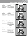
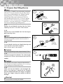
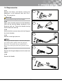
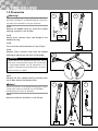
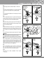
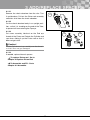
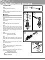
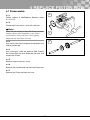
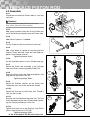
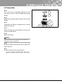
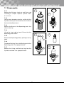
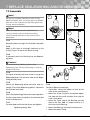
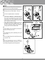
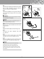
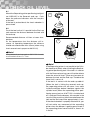
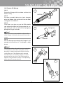
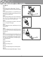
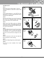
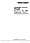
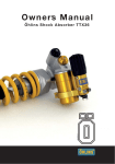
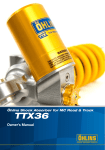
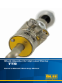
Shock Absorber for High Level Racing
TTR
Owner’s Manual/ Workshop Manual
Öhlins Racing AB - The Story
world titles are definitive proof that Öhlins shock
absorbers offer outstanding performance and
reliability.
Every product has gone through rigorous
testing and engineers have spent thousands
of hours, doing their very best to use every
possible experience from our 30 years within the
racing sport.
By installing this shock absorber on your
vehicle you have made a clear statement…
you are a serious driver with a focus on getting
the maximal handling ability and outstanding
feedback from your vehicle. Along comes the
fact that your shock absorber will be a long
lasting friend, delivering the very best of comfort
and performance every time you go for a drive.
Go explore!
It was the 1970’s, a young man named Kenth
Öhlin spent most of his spare time pursuing his
favourite sport: motocross. A careful observer,
Kenth’s attention was continually drawn to one
specific detail - motocross bikes had more engine
power than their suspension could handle. It
was not long before Kenth realised that better
performance could be achieved by improved
wheel suspension.
Öhlins Racing was established in 1976, and
just two years later the company won its first
World Championship title.
Despite being in the business for 30 years, the
search for perfection and new functions is still
the main focus of the company.
Congratulations! You are now the owner of
an Öhlins Shock Absorber. More than three
hundred World Championships and other major
In This Manual
Safety Precautions
Service & Maintenance
Design and Functioning
External Adjusters
Zeroing
Valve Overview
Revalve
Workshop Section
Page
2
3
3
4
5
8
9
12
1
Safety Precautions
Note!
Safety Symbols
The shock absorber is an important part of the
vehicle and will affect the stability.
In this manual, mounting instructions and
other technical documents, important information concerning safety is distinguished
by the following symbols:
Note!
Read and make sure that you understand the
information in this manual before you use this
product. If you have any questions regarding
installation or maintenance please contact an
Öhlins dealer.
The Safety Alert Symbol means: Warning!
Your safety is involved.
Warning!
Warning!
The Warning Symbol means: Failure to
follow warning instructions can result in
severe or fatal injury to anyone working with,
inspecting or using the shock absorber, or
to bystanders.
Öhlins Racing AB can not be held responsible for
any damage to the shock absorber, vehicle, other
property or injury to persons, if the instructions for
maintenance are not followed exactly.
Warning!
Caution!
This product contains pressurized nitrogen
gas (N2). Do not open, service or modify this
product without proper education (authorized
Öhlins dealer/distributor) and proper tools.
The Caution Symbol means: Special
precautions must be taken to avoid damage
to the shock absorber.
Note!
Warning!
The Note Symbol indicates information that
is important regarding procedures.
After installing this product, take a test drive at
low speed to make sure that your vehicle has
maintained its stability.
Warning!
Note!
If the suspension makes an abnormal noise, or the
function is irregular, or if you notice any leakage
from the product, stop the vehicle immediately and
return the product to an Öhlins Service Centre.
When working on this product, always consult your
Vehicle Service Manual.
Note!
This Manual shall be considered a part of the
product and shall therefore accompany the
product throughout its life cycle.
Warning!
The product warranty shall only apply if this
product has been operated and maintained in
accordance with recommendations in this manual.
If you have any questions regarding usage,
service, inspection and maintenance please
contact Öhlins.
© Öhlins Racing AB. All rights reserved. Any reprinting
or unauthorized use without the written permission of
Öhlins Racing AB is prohibited.
Printed in Sweden.
2
service and maintenance
After every use
• Measure the position of the separating piston.
See Chapter 9 Check Oil Level in the Workshop Section.
• Look for oil leakage. By keeping the damper
clean and dry, any leakage will be easy to detect. If oil is leaking from the X-ring seal repeatedly, replace X-ring and inspect the piston
rod for imperfections on the surface.
• Inspect the dampers for external wear or damage.
• Check the spherical bearings regularly for excessive play. On installations where the spring
is not of coil over type, a gap is more critical as
the bearings will see loads in both directions.
Recommended Service Intervals
• After 30hours or 6000Km
• After 15hours or 3000Km if working temperature exceeds 110°C
If the shock absorber reaches a temperature of
140°C or more it needs immediate service.
Recommended service, change/ replace;
• oil
• o-rings, x-rings
• piston band
• bushings
Caution!
If you have any questions regarding service and
maintenance, please contact Öhlins.
design and functioning
Öhlins now releases the TTR damper – a
4-way fully independent adjustable damper based
on well proven technology that has been behind
winning success for many years in high-end
factory racing in IndyCar, Le Mans and DTM.
This high end racing damper is now available
for teams seeking optimal performance and ontrack success.
Features include a precise valving system, both
high and low speed can be zeroed externally to
ensure an accurate matching between dampers
while at the same time maintaining reference
clicks.
The TTR damper combines top performance
with user friendly handling, for instance change
valving in close to one minute.
The damper also comes with valving
simulation software, drastically reducing time
from idea to ready damper and helps making
accurate adjustments at the track.
Features
• 4-way fully independent adjustable damper
• Solid piston
• Well proven valve technology
• Through-rod design to minimize hysteresis
• Large adjustment range
• Top performance combined with easy handling
• Change valving in close to 1 minute
• Comes with valving simulation software
• Precise valving system, both low- and highspeed can be zeroed externally.
3
external adjusters
Low Speed Compression Damping Adjuster (LSC)
Adjuster type:
Identification:
Number of positions:
Click position 0:
Bleed adjuster
Gold coloured knob
Approx. 55 (10 clicks/turn)
Fully counter clockwise at minimum force (orifice open)
Low Speed Rebound Damping Adjuster (LSR)
Adjuster type:
Identification:
Number of positions:
Click position 0:
Bleed adjuster
Silver coloured knob
Approx. 55 (10 clicks/turn)
Fully counter clockwise at minimum force (orifice open)
High Speed Compression Adjuster (HSC)
Adjuster type:
Poppet valve
Identification:
Screw with internal 3mm hex (inside the gold casing)
Number of positions: approx. 40 (8 clicks/turn)
Click position 0:
Fully counter clockwise at minimum force (spring min preloaded)
High Speed Rebound Adjuster (HSR)
Adjuster type:
Poppet valve
Identification:
Screw with internal 3mm hex (inside the silver casing)
Number of positions: approx. 40 (8 clicks/turn)
Click position 0:
Fully counter clockwise at minimum force (spring min preloaded)
4
zeroing
Zeroing result
See the examples below for results after calibrating Low Speed and High Speed Valve.
To calibrate according to the example below
see Low Speed Zeroing and High Speed Zeroing
on the following two pages.
Note!
When calibrating, we recommend to calibrate
Low Speed and High Speed in the same order as
performed below. The Low Speed Bleed affects
the High Speed Valve.
Low Speed Zeroing
1
2
Actual curve
Reference curve
Calibrate Low Speed Bleed
High Speed Zeroing
3
4
Calibrate High Speed Valve
Recommended Tools when Zeroing
Tool
Part no
Adjustment tool
01899-01
Screwdriver
1mm hex screwdriver
1.3mm hex screwdriver
3mm hex screwdriver
5
zeroing
Low Speed Zeroing
Choose one of your shock absorbers that is closest to the Valving
Reference Program (VRP) as a reference.
2
1
Check in the dyno the number of
clicks needed to close or open the adjuster to
match your reference.
2
Turn the adjuster to fully open by turning counter
clockwise until stop.
3
3
Note that there are two lock screws, one on each
side of the adjuster. Unlock these;
3.1
Turn the adjuster half a turn clockwise so that
you can unlock (½ turn) the screw that was facing in. Use a 1.3mm hex screwdriver.
3.2
Turn the adjuster counter clockwise until stop.
Loosen the screw facing out.
3.1
½ turn
½ turn
3.2 ½ turn
4
Use a screwdriver and turn the slotted centre
screw. Turn the number of clicks that was defined in step 1. Note that one groove, or the distance between two peaks, equals one click. Turn
clockwise to obtain increased force. Turn counter
clockwise to obtain less force.
4
=1 click
=1
=1
etc
5
Push the knob towards the cylinder head and at
the same time lock the screw facing out.
6
Turn the adjuster half a turn clockwise. Push the
knob and lock the screw that was facing in.
5
7
Turn the adjuster to fully open by turning counter
clockwise until stop.
8
Set the adjuster to the desired number of clicks.
Run the shock absorber once again in the dyno to
confirm your set-up.
6
zeroing
High Speed Zeroing
Note!
2
When zeroing, first zero low speed and then high
speed.
1
Loosen the 1mm hex screws. Note that there are
two on each side of the two Adjustment housings.
+
3A
1
2
Use a 3mm hex screwdriver to fixate the Adjustment screw.
3
Use tool 01899-01 (3A) to zero.
Turn counter clockwise to obtain less damping
force. Turn clockwise to obtain increased damping force.
-
3
2
Fixate Adjustment screw
Note!
Normally you will only need to turn until you hear a
noticeable click, or less.
4
Lock the 1mm hex screws by only slightly tightening each screw at a time in a cross pattern not
to make the Inserts skewed into the Adjustment
housing.
7
valve overview
G47
G57
Valve and Valve Seat
G67
D50
D70
06183-47
06183-57
06183-67
06185-50
06185-70
06198-47
06198-57
06198-67
06197-50
06197-70
Shuttle Guide
Spring
x.x
Shuttle Guide
Spring
Part No.
ØD (mm)
Part No.
T (mm)
(N/mm)
06195-10
1.0
06196-20
1.9
20
06195-15
1.5
06196-30
2.1
30
06195-20
2.0
06196-40
2.25
40
06196-50
2.34
50
8
revalve
Recommended Tools when Revalving
Tool
Part no
Clamp tool
01878-01
Adjuster house tool
01898-01
Öhlins High Performance fluid
01304-XX
1
Torque wrench
Small pliers
Note!
Every time you revalve the oil level and the
amount of air in the shock absorber will be slightly
increased. Therefore we recommend that after
approximately five [5] revalvings Check the Oil
Level and Vacuum Fill, see Chapter 9-10 in the
Workshop Section.
2
1
Put the shock absorber in a vice. Use clamp tool
01878-01.
2
Depressurize the shock absorber. See chapter
1 Pressure.
3
3
Use tool 01898-01 and a torque wrench. Press
the tool down in a straight line so that the pins on
the tool are aligned with the holes in the Adjustment housing. Remove the Adjustment housing.
To Replace Valve Spring - Go to 4.1
To Replace Valve/ Valve seat and Shuttle Guide - Go to 4.2
9
revalve
4.1 Replace Valve Spring
4.1.1
4.1.1
Use small pliers and remove the Valve spring.
4.1.2
Replace the Spring.
4.1.3
Pour oil up to the edge of the valve cavity.
Note!
Only use Öhlins High Performance fluid.
4.1.4
Mount the Adjustment housing.
01898‑01 and a torque wrench.
Tightening torque 10Nm
Use
tool
4.1.3
4.1.4
10
revalve
4.2 Replace Valve and Valve seat
4.2.1
Use small pliers and remove the Valve spring.
4.2.1
4.2.2
Use small pliers and remove the Valve. Pour out
some of the oil that may come with the Valve.
4.2.2
4.2.3
Remove the Shuttle guide and Valve seat.
4.2.3
4.2.4
Remove the Check valve shim, Wave washer,
Support shim and the Circlip from the Valve seat.
4.2.5
Put the Check valve shim, Wave washer, Support
shim and the Circlip on the new Valve seat.
4.2.4
Note!
Shuttle guide
Note the Wave washer position.
Circlip
4.2.6
Put the new Valve seat on the Shuttle guide. Note
the position of the Shuttle guide legs. Make sure
that the Valve seat snaps on to the Shuttle guide.
Valve seat
4.2.7
Put the Shuttle guide, Valve and Spring back into
the Cylinder head.
4.2.8
Pour oil up to the edge of the cavity (see figure 4.1.3).
Support shim
Wave
washer
Check valve
shim
Valve seat
4.2.6
Note!
Only use Öhlins High Performance fluid.
4.2.7
4.2.9
Mount the Adjustment housing. Use tool
01898‑01 and a torque wrench (see figure 4.1.4).
Tightening torque 10Nm
11
workshop section
Contents
Chapter
Recommended Tools
Page
Tools
12
1 Pressure
1.1 Prepare Gas Filling Device
13
1.2 Depressurize
14
1.3 Pressurize
15
2 Reclock Top Eye
16
3 Add/Replace Spacers
3.1 Disassemble
17
3.2 Assemble
19
4 Replace Piston Rod
4.1 Disassemble
20
4.2 Assemble
21
5 Replace Cylinder Tube
5.1 Disassemble
22
5.2 Assemble
23
6 Replace Top Eye
6.1 Disassemble
25
6.2 Assemble
26
7 Replace Seals/Bushings/Bearings
and/or Membrane
7.1 Disassemble 27
7.2 Assemble 28
8 Fill Oil
29
9 Check Oil Level
31
10 Adjust Oil Level
10.1 Prepare Oil Syringe
32
10.2 Add Oil
33
10.3 Remove Oil
34
Tool
Part No
Assembly lubricant - Red grease
00146-01
Soft jaws
00727-02
Soft jaws
00727-03
Sleeve
00737-05
Spanner
00738-01
Vice
00773-01
Öhlins High Performance Fluid
01304-XX
Peg spanner
01761-01
Peg spanner
01761-03
Öhlins 21mm wrench
01772-03
Gas Needle Housing
01779-02
Gas Filling Device
01781-01
M5 Adapter
01820-01
Öhlins Vacuum Filling Machine
01840-01
Öhlins Vac. Filling Machine Manual
07221-01
Mounting Sleeve
01861-XX
Separating piston positioning tool
01876-XX
Separating piston positioning spacer
01877-5X
Clamp tool
01878-01
Syringe kit
01881-01
Adjuster House Tool
01898-01
Spring PL Tool
03199-01
Positioning pin
24602-01
Adjustable wrench
Allen key 3mm
Allen key 6mm
Circlip pliers
Heat gun
Loctite
Nitrogen gas (N2)
Torx T20 and T25 Screwdriver
Torque wrench
Vice with soft jaws
Wrench 10, 11 and 14mm
12
1 pressure
1.1 Prepare Gas Filling Device
Note!
If you have a TTX46MT shock absorber combined
with the TTR shock absorber the gas filling device
must to be modified before use. Replace needle
housing (part no. 01779-01) included in the
standard gas filling device (part no. 01781‑01)
with needle housing (part no. 01779‑02). Needle
housing 01779‑02 can be used on most Öhlins
products.If you are working on a TTX46MT you do
not need to modify the gas filling device.
1
11 mm
14 mm
Quick
coupling
01778-01
2
1.1.1
Remove the old Needle housing from the Quick
coupling. Use an 11 mm and 14 mm wrench.
Replace
01779-01
1.1.2
Remove the current Needle from the Housing by
gently pushing it out.
Note!
11 mm
3
Push the needle against a surface that will not
damage the needle tip (some wood or plastic is
recommended).
10 mm
1.1.3
Put the Needle into the new Needle housing and
screw it back on the Quick coupling.
Use a 10 mm and 11 mm wrench.
01779-02
Caution!
Use a low tightening torque, approximately 5 Nm.
4
1.1.4
Check the length of the Needle. The visible length
should be 14‑20 mm (measured to the tip of the
needle).
Caution!
If the Needle is too short, it may not reach all the
way through the Rubber membrane. If it is too long
it may damage the Separating piston.
5
1.1.5
Make sure that the Needle is not damaged. Replace if you find burrs around the tip. Carefully
grab the Needle between two fingers and gently
move your fingers along the needle to look for
damage.
Warning!
Be careful when checking the needle.
13
Quick
coupling
01778-01
1 pressure
1.2 Depressurize
1.2.1
Remove the Screw and Washer covering the
Membrane at the Reservoir end cap. Use a
Torx T20 screwdriver.
1
Warning!
Be careful when working with the Needle.
1.2.2
Apply some assembly lubricant on the Needle tip.
Insert the tip into the Rubber membrane in the
Reservoir end cap. Thread the Needle housing
into the Reservoir end cap.
2
1.2.3
Attach the Quick-connect hose with the Gauge to
the shock absorber.
3
1.2.4
Note the current gas pressure.
Note:
The Gauge will show approx. 1 bar less (the total
gas volume will be greater when the gauge is
attached). This means that you need to add 1
bar to your noted gas pressure to get the correct
value.
5
1.2.5
Remove the Gauge to depressurize the shock absorber.
1.2.6
Remove the Needle.
6
14
4
1 pressure
1.3 Pressurize
1
Warning!
2
Only use nitrogen gas (N2) to pressurize the shock
absorber. Nitrogen is an inflammable gas that does
not affect the materials in the gas reservoir.
1.3.1
Remove the Needle cover (A). Insert Gas needle
housing assembly in the fill hole.
A
1.3.2
Mount Quick connect hose and Gauge to the
Needle housing.
fill hole
1.3.3
Pressurize the shock absorber to 5 bar (75psi).
1.3.4
Remove Quick connect hose from the Needle
housing to release gas pressure in the gauge.
3
Warning!
Never remove the Needle housing from the fill
hole with a pressurized Gauge still connected.
A pressurized needle can be hazardous. If nitrogen is injected into the body there is a risk for
personal injury or death.
1.3.5
Remove the Gas needle housing assembly from
the fill hole. Mount the Needle cover.
Note!
4
Make sure there is no leakage (nitrogen gas). Apply
some soap water on the end cap and Rubber
membrane and check for bubbles.
1.3.6
Mount the Washer and Screw in the fill hole.
15
Warning!
5
2 reclock top eye
2.1
Release gas pressure. See chapter 1 Pressure.
2
3
5
6
4
2.2
Mount the shock absorber in a vice with soft jaws,
clamp at the flat sides of the Cylinder head.
2.3
If any, remove the Spacers in the top eye. Use two
screwdrivers.
2.4
Use an adjustable wrench. Loosen the Top eye by
turning counter clockwise. Ensure that the spanner covers both sides of the Bearing hole.
2.5
Mount the Peg spanner (part no 01761-03) on the
Reservoir end cap. Note that the pins go into the
pressure indicator holes.
2.6
Rotate the Reservoir end cap in any direction just
enough to ensure that the Top eye follows the End
cap. If it does not, loosen the Top eye a little more.
7
2.7
Turn the Top eye clockwise by hand until it stops.
Note!
If it is not possible to turn it by hand, use an
adjustable wrench and carefully turn the Top eye.
2.8
Use a Peg spanner. Turn the Reservoir end cap
counter clockwise until the Top eye points in a 90º
angle from desired position. (Turning the End cap
counter clockwise ensures that the Reservoir end
cap and the Top eye turn together).
8
9
90º
2.9
Use an adjustable wrench and turn the Top eye
90º to the desired position. Ensure that the spanner covers both sides of the Bearing hole.
90º
2.10
Pressurize the shock absorber. See chapter
1 Pressure.
16
3 add/replace spacers
3.1 Disassemble
2
3.1.1
Release gas pressure. See chapter 1 Pressure.
3.1.2
Pull the Piston rod to fully extended position.
3.1.3
Mount the shock absorber in a vice with soft jaws.
4
3.1.4
To remove the Spring seats, use tool 03199-01.
3.1.5
Loosen the Lock nut at the End eye. Use Öhlins 21mm wrench (part no 01772-03).
3
5
3.1.6
Put the shock absorber in a horizontal position.
Unscrew the End eye.
Note!
If the Piston rod rotates with the End eye; clamp
the Piston rod in a vice.
3.1.7
Remove the Lock nut and External spacers, if any.
5
3.1.8
Put the shock absorber upside down in a vice
with soft jaws. Clamp gently at the flat sides of
the Cylinder head.
3.1.9
Compress the shock absorber slightly to prevent
the internal piston rod from leaving the seal in
the cylinder head. If the top eye leaves the seal,
oil will leak out into the top eye cavity before it
comes out through the holes of the top eye.
10
3.1.10
Loosen the Cylinder end cap. Use a Peg spanner
(part no 01761-01).
8
17
6
3 add/replace spacers
3.1.11
Remove the shock absorber from the vice. Turn
it upside down. Pull out the Piston rod assembly
and drain all oil from the shock absorber.
11
3.1.12
Put the shock absorber body in an upright position, so that it is standing on the end of the Tube,
to prevent oil from entering the Top eye.
3.1.13
Put some assembly lubricant on the End eye
thread of the Piston rod. Rotate the Cylinder end
cap when sliding it up the Piston rod so that it
does not get stuck.
12
Caution!
Pull the Cylinder end cap carefully over the thread
so that it does not get damaged.
3.1.14
If needed, replace Internal spacers.
To replace Piston rod - Go to
Chapter 4 Replace Piston Rod
To Assemble and Fill - Go to
Chapter 3.2 Assemble.
18
13
3 add/replace spacers
3.2 Assemble
1
3.2.1
If needed, add Internal spacers.
3.2.2
Carefully mount the Cylinder end cap on the Piston rod assembly.
2
3
6
Caution!
5
Pull the Cylinder end cap carefully not to damage
the End cap seal.
3.2.3
Put the shock absorber in the vice with the Cylinder tube up.
4
3.2.4
Mount tool 01861-XX in the Cylinder tube.
3.2.5
Push the Piston rod assembly into the Cylinder
tube until the Piston seal enters the Inner tube.
Remove the Mounting sleeve. Push the Piston rod
assembly all the way and engage the thread to
the End cap.
3.2.6
Screw the End cap on the Tube.
Tightening torque 50Nm
8
3.2.7
Mount the External spacers on the Piston rod.
Thread the Lock nut to the inner end of the thread.
3.2.8
Mount the End eye on the Piston rod. Thread it
until you feel a stop.
9
3.2.9
Turn the shock absorber to an upright position.
Clamp the End eye in a vice.
3.2.10
Tighten the Lock nut to the End eye. Use Öhlins
21mm wrench (part no 01772-03)
Tightening torque 25Nm
Go to Chapter 8 Fill Oil and
Chapter 1 Pressure.
19
4 replace piston rod
4.1 Disassemble
2
4.1.1
Follow chapter 3 Add/Replace Spacers steps
3.1.1-3.1.12.
4.1.2
Clamp the Piston rod in a vice with soft jaws.
Note!
Clean the rod carefully to keep the Piston rod from
rotating. Spray some degreaser on the Piston
rod to make it stick to the jaws. Avoid getting
degreaser into the Piston rod seal.
3
4.1.3
Use a 6mm allen key and loosen the thread in the
Internal piston rod.
4
4.1.4
Use a heat gun. Heat the external Rod. Protect
the Piston from the heat. Separate the rods and
remove the Piston.
4.1.5
Remove Internal spacers, if any.
4.1.6
Remove the Cylinder end cap from the Piston rod.
4.1.7
Remove the Piston rod from the vice.
20
4 replace piston rod
4.2 Assemble
1
4.2.1
Clamp the new external Piston rod in a vice with
soft jaws.
min. 25mm
Caution!
Do not clamp the external Piston rod closer
than 25mm from the Piston position.
4.2.2
Add some assembly lubricant on the Piston rod.
Install the End cap carefully from the Piston side.
4.2.3
Add Internal spacers, if needed.
5
4.2.4
Put the Piston on the new internal Piston rod.
4.2.5
Add a few drops of Loctite on the thread of the
Internal Piston rod and screw the two Rods together. Use a torque wrench.
Tightening torque 22Nm
8
4.2.6
Put the Cylinder head in a vice, Cylinder tube up.
4.2.7
Mount the Piston rod assembly in the Cylinder
tube. Use Öhlins mounting sleeve 01861-XX.
4.2.8
Screw the End cap on the Tube and tighten. Use
Peg spanner (part no 01761-01)
Tightening torque 50Nm.
7
6
4.2.9
Mount the External spacers on the Piston rod.
Thread the Lock nut to the end of the thread.
12
4.2.10
Mount the End eye on the Piston rod. Thread it
until you feel a stop.
4.2.11
Remove the Cylinder head from the vice. Turn the
shock absorber so that the Cylinder head is pointing up. Clamp the End eye in the vice.
10
4.2.12
Tighten the Lock nut on the End eye. Use Öhlins
21mm wrench (part no 01772-03)
Tightening torque 25Nm
Go to Chapter 8 Fill Oil and 1 Pressure
21
5 Replace cylinder tube
5.1 Disassemble
5.1.1
Release gas pressure. See chapter 1 Pressure.
3
5.1.2
Put the shock absorber in a vice with soft jaws
with the Piston rod pointing up. Clamp at the flat
sides of the Cylinder head.
2
5.1.3
Remove the Cylinder end cap. Use a Peg spanner
(part no 01761-01).
4
5.1.4
Remove the shock absorber from the vice. Turn
it upside down. Pull out the Piston rod and drain
all oil.
6
5.1.5
Put the Cylinder head with the Cylinder tube unit
in the vice. Clamp at the Cylinder head.
5.1.6
Mount the Piston rod and End cap assembly temporarily into the shock absorber. Use Mounting
sleeve (part no 01861-XX).
5
7
5.1.7
Screw the End cap into the Tube until you feel a
stop. Then, loosen just so that the End cap easily
can be removed by hand later on.
5.1.8
Mount Sleeve (part no 00737-05) on the Outer
tube. Put the top of the Sleeve at the same height
as the end of the Outer tube.
5.1.9
Mount Spanner (part no 00738-01) on the Sleeve,
make sure it grips the area around the Cylinder
end cap.
9
5.1.10
Loosen the Outer tube from the Cylinder head.
8
Note!
If the Outer tube does not come off, heat the
Cylinder head with a heat gun. Protect the Adjuster
from the heat not to damage the o-rings in the
valve units.
22
5 Replace cylinder tube
5.1.11
Remove the Sleeve and the Spanner.
12
13
5.1.12
Unscrew the Cylinder end cap. Pull out the Piston
rod assembly.
5.1.13
Unscrew the Outer tube and remove it.
14
5.1.14
Remove the Inner tube by hand.
5.1.15
If necessary, replace Inner and/or Outer tube.
5.2 Assemble
5.2.1
Clean the Cylinder head thread from Loctite.
4
Caution!
Make sure old Loctite does not fall into the shock
absorber.
To remove the Separating plate - go to
Chapter 7
2
5.2.2
Add some assembly lubricant inside the end of
the new Inner tube.
1
5.2.3
Push the new Inner tube on the Separating plate.
Make sure that the side with assembly lubricant is
facing the Separating plate.
5.2.4
Put 3 drops of Loctite 243 on the new Outer tube
thread. Apply a thin layer of assembly lubricant on
the surface meeting the Cylinder head O-ring. Apply some assembly lubricant inside the other end
of the Outer tube thread and the surface that will
meet the End cap O-ring.
23
5 Replace cylinder tube
5.2.5
Screw the new Outer tube in place by hand.
6
5.2.6
Mount the Piston rod and End cap assembly in
the shock absorber. Use Mounting sleeve (part no
01861-XX).
5.2.7
Screw in the Cylinder End cap enough to support
the Outer tube when tightening the Outer tube in
the Cylinder head. Recommended position for the
End cap; 1-2mm above the Outer tube end.
Caution!
Never have the end cap flush with the Outer tube
when the Outer tube is installed on the Cylinder
head. The high torque used to install the Outer
tube can damage the Cylinder end cap if it has
been threaded in too much.
9
5.2.8
Mount Sleeve (part no 00737-05) on the Outer
tube. Put the top of the Sleeve at the same height
as the end of the Outer tube.
8
5.2.9
Mount the Spanner on the Sleeve. Place it in the
same area as the Cylinder end cap.
5.2.10
Tighten the Outer tube to the Cylinder head.
Tightening torque 90Nm
To assemble the Shock absorber go to
Chapter 4.2.8 Replace Piston Rod.
24
6 replace top eye
6.1 Disassemble
6.1.1
Release gas pressure. See chapter 1 Pressure.
2
3
4
6.1.2
If any, remove the Spacers in the top eye. Use two
screwdrivers.
6.1.3
Mount the shock absorber in a vice with soft jaws.
Clamp at the flat sides of the Cylinder head.
6.1.4
Use an adjustable wrench. Loosen the Top eye by
turning counter clockwise. Ensure that the spanner covers both sides of the Bearing hole.
6.1.5
Continue to screw the Top eye counter clockwise
by hand, 3-5 turns. The Top eye will thread out of
the shock absorber while the Reservoir end cap
stays.
5
Caution!
Do not unthread the Top eye so much that it
comes off the Reservoir end cap.
6.1.6
Push the Reservoir end cap down by hand. The
Top eye will follow the Reservoir end cap into the
shock absorber.
7
6.1.7
Insert an allen key into the small hole on the Cylinder head. Remove the Circlip.
6.1.8
Pull the Top eye and the Reservoir end cap out of
the Cylinder head.
8
6.1.9
Remove the Top eye from the Reservoir end cap.
9
25
6 replace top eye
6.2 Assemble
6.2.1
Put a thin layer of assembly lubricant on the
new Top eye, put it where the Separating piston
moves.
6
5
6.2.2
Add some assembly lubricant on the new Top eye
thread.
6.2.3
Thread the new Top eye a couple of turns into the
Reservoir end cap.
6.2.4
Mount the Top eye and Reservoir end cap unit
into the Cylinder head.
6.2.5
Mount the Circlip.
Note!
Ensure that the Circlip opening is not where the
hole that is used to remove it.
6.2.6
Set the clocking of the Top eye. See chapter “Reclock Top Eye”.
6.2.7
Drain oil from the holes of the Top eye.
Go to Chapter 8 Fill Oil and 1 Pressure.
26
7 replace seal/bushing and/or membrane
7.1 Disassemble
2
7.1.1
Remove the End eye, Lock nut and Piston rod
according to chapter “Replace Cylinder Tube”
5.1.1‑5.1.12.
5
7.1.2
Let the shock absorber stand for a while with the
Cylinder head up so that the oil from the inside of
the Inner tube flows down.
7.1.3
Remove the Screw of the Separating plate. Use
a 3mm allen key.
7.1.4
Lift up the Inner tube by hand. Ensure that the
Separating plate follows.
4
6
7.1.5
Remove the Separating plate by pushing it out by
hand.
7.1.6
To replace Bushing; Press the Bushing out of the
Separating plate. Use appropriate tool.
7
7.1.7
Remove the X-ring and Back-up ring from the
Cylinder head hole. Use appropriate tool.
27
7 replace seal/bushing and/or membrane
7.2 Assemble
Note!
1
Always put assembly lubricant on new O-rings
before assembly. Also, put a thin layer of assembly
lubricant on the surfaces that will slide against the
O-rings during installation.
3
Note!
Mount the Membrane of the Reservoir end
cap by pushing it into the hole after adding
some assembly lubricant to the surface of the
Membrane.
5
7.2.1
Mount the Back-up ring in the Cylinder head hole.
7.2.2
Apply a thin layer of assembly lubricant on the
X‑ring. Place it on top of the Back-up ring.
7.2.3
If removed, press the Bushing into the Separating plate.
Caution!
Be careful with the Sealing surface of the
Separating plate. Ensure the Bushing is correctly
aligned in the hole.
8
7.2.4
Put some assembly lubricant on the O-ring on the
Separating plate. Put the Inner tube on the Separating plate by hand.
7.2.5
Mount the Separating plate and Inner tube assembly. Ensure the Separating plate is centred in
the Cylinder head hole.
7.2.8
To mount Spherical bearings;
• If possible, round the edges on one of the
sides of the new Bearing.
• Mount on of the Circlips in the groove opposite side with the small chamfer. Use a pair of
small circlip pliers.
• Clean the Outer ring of the Bearing and the
hole of the Eye. Add 1-2 drops Loctite, in a
thin layer, to the Bearing.
• Mount the Bearing. Use Manual arbor press.
• Mount the other Circlip.
7.2.6
Clock the Separating plate to the correct position.
Put the screw hole in the plate in line with the hole
of the Cylinder head.
7.2.7
Put one drop Loctite on the Screw and tighten.
Tightening torque 3Nm
28
8 fill oil
Note!
Use Öhlins Vacuum Filling Machine. See Owner’s
Manual 07221-01 for correct procedure.
4
5
8.1
Release gas pressure. See chapter 1 Pressure.
8.2
Open the Low speed adjusters completely.
8.3
• If the shock absorber is still filled with oil:
Drain all oil by removing the O-ring, Oil filling
screw (Use a Torx T25 screwdriver). Push the
Piston rod back and forth to drain all oil. Mount
the O-ring back after draining.
• If the shock absorber is empty: Remove the
Oil filling screw on the Cylinder head. Use a
Torx T25 screwdriver. Make sure to keep the
O-ring in place on the Cylinder head.
8
6
7
8.5
Use M5 adapter (part no 01820-01) and mount it
where the Oil filling screw was.
8.6
Mount Separating piston positioning tool (part
no 01876-XX).
8.7
Mount the Separating piston positioning spacer
(part no 01877-5X).
8.8
Mount the Positioning pin (part no 24602-01).
Note the different diameters on the pin as well as
on the Separating piston positioning spacer.
29
8 fill oil
8.9
Mount the Gas needle unit and the Quick-connect
hose to keep atmosphere pressure inside the
Reservoir during the filling procedure.
12
8.10
Connect the Adapter to the Vacuum filling machine. See Owner’s Manual 07221-01 for correct
procedure.
Caution!
Lower the Air pressure of the machine to 2.5±0.5
bar when filling TTX dampers.
14
Note!
Make sure spacer (part no 01877-5X) stays in
place during the filling procedure.
8.11
Disconnect the shock absorber from the Vacuum
filling machine.
8.12
Replace the M5 adapter with the Filling screw.
8.13
Pressurize the shock absorber. See chapter 1 Pressure.
15
8.14
Remove the Quick connect hose at the Needle
housing and unscrew the Needle housing.
8.15
Remove the Separating piston positioning tools.
Twist the 01877-5X spacer tool and pull out.
Note!
If you find it hard to remove the separating
positioining tools if the shock absorber is
pressurized; remove the separating piston
positioning tools after removing the gas needle
unit, then reinstall the needle unit and pressurize
the damper.
30
9 check oil level
9.1
Mount the Separating piston positioning tool (part
no 01876-XX) in the Reservoir end cap. Push
down the pressure indicators with the two pins
of the tool.
If the tool is pushed back, the shock absorber is
pressurized.
9.2
Push the tool so that it is parallel to the End cap
and measure the distance between the tool and
the end cap.
Recommended distance >0-2mm at room temperature.
As the temperature rises the distance will increase. At operating temperature the distance
should not extend more than 4,5mm (when using
short reservoir end cap part no 06121-01).
2
>0-2mm
1
Note!
If long reservoir end cap part no 06121-02 is used,
recommeded distance > 7mm.
Note!
If the Separating piston is not parallel to the Cylinder head (up to 3mm) when installing the Separating piston positioning tool. If the tool is in contact
with the Reservoir end cap you will not be able to
know the actual oil level. There must be some air
between the tool and the End cap. Therefore the
lower limit is set to >0.
If the tool is in contact with the end cap add oil.
(When the tool is hitting the reservoir end cap,
the separating piston can still move 1 mm more
inside the damper before it bottoms against the
cylinder head.) When the separating piston positioning spacer (part no. 01877-5X) is installed and
oil is pressed into the damper, for example in the
vacuum filling machine, the distance between the
tool and the end cap will be approximately 1 mm.
If the shock absorber is properly filled with oil, you
will not notice any movement of the separating
piston when the damper is getting pressurised. If
the separating piston moves further in, there is air
in the oil.
31
10 adjust oil level
10.1 Prepare Oil Syringe
10.1.1
Pull out the Plunger with the rubber seal from the
Plastic casing.
1
01879-01
10.1.2
Put some assembly lubricant or shock absorber
oil on the Rubber seal and install it into the Steel
casing, part no. 01880-01.
10.1.3
Fill oil into a cup (you can use the Öhlins bottle
cap) and put the tip of the Syringe under the surface of the oil and suck oil into the Syringe by
pulling the Plunger outwards.
2
Red grease
Note!
There is no stop, so pay attention to the position
of the Plunger so that you do not pull it out of the
casing.
01880-01
10.1.4
Turn the Syringe up and push the Plunger in just
enough to evacuate the air. The Syringe is ready
to use.
Note!
The Plunger rubber will swell from shock absorber
oil. This process, that takes some time, can be
annoying, so always remove the Piston from the
casing after use. If the Rubber seal is removed
from the Piston and carefully cleaned, it can be
reused, but the low price of this Piston makes a
frequent change the best solution. The Separating
piston moves 2 mm per ml of oil.
3
4
32
10 adjust oil level
10.2 Add Oil
2
10.2.1
Release gas pressure. See chapter 1 Pressure.
Leave the Needle unit and Quick connect hose mounted.
10.2.2
Put the shock absorber in a vice (00773-01) with
tool 01878-01. Place the shock absorber with the
Oil filling screw pointing up.
10.2.3
Remove the Oil filling screw on the Cylinder head.
Use a Torx T25 screwdriver. Make sure to keep
the O-ring in place on the Cylinder head.
3
10.2.4
Mount Oil syringe (part no 01881-01). See chapter “10.1 Prepare Oil Syringe”.
10.2.5
Mount Separating piston positioning tool (part
no 01876-XX).
10.2.6
Mount the Separating piston positioning spacer
(part no 01877-5X) and the Positioning pin (part
no 24602-01)
4
5
10.2.7
Insert oil with the Syringe into the Reservoir until
the Piston of the Syring gets solid. The Separating
piston has now bottomed out towards the pressure indicators positioned by the Separating piston positioning tools.
6
10.2.8
Remove the Syringe.
10.2.9
Mount the Oil filling screw.
10.2.10
Remove the Separating piston positioning tools.
10.2.11
Pressurize the shock absorber. See chapter 1 Pressure.
33
10 adjust oil level
10.3 Remove Oil
10.3.1
Release gas pressure. See chapter 1 Pressure.
Leave the Needle unit and Quick connect hose
mounted.
2
10.3.2
Put the shock absorber in a vice (00773-01) with
tool 01878-01. Place the shock absorber with the
Oil filling screw pointing up.
10.3.3
Remove the Oil filling screw on the Cylinder head.
Use a Torx T25 screwdriver. Make sure to keep
the O-ring in place on the Cylinder head.
3
10.3.4
Mount 1mm thick Shim stacks (or Washers)
around the two pins of the Separating piston positioning tool. (To help setting the Separating piston in the correct position).
10.3.5
Mount the Separating piston positioning tool (part
no 01876-XX). Push it in slowly until the Shim
stack/Washers are in contact with the Reservoir
end cap. Oil will now flow out through the screw
hole.
5
10.3.6
Keep the pressure on the tool and mount the
Screw to prevent air from entering.
10.3.7
Remove the Separating piston positioning tool.
6
10.3.8
Pressurize the shock absorber. See chapter
1 Pressure.
34
4
1mm
Öhlins Owner’s/Workshop Manual TTR | Part No. 07452-01_0 | Issued 2011-07-07 | © 2011 Öhlins Racing AB
Your Öhlins retailer:
Öhlins Racing AB
Box 722
SE-194 27, Upplands Väsby
Sweden
Phone: +46 (0)8 590 025 00
Fax: +46 (0)8 590 025 80
www.ohlins.com