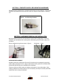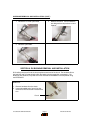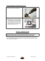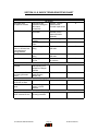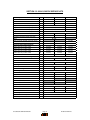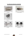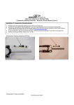
1
2004 SERVICE MANUAL
Manitou Q shocks
28209 Avenue Stanford, Valencia, California 91355
661 257-4411 | fax 661 294-4179 |
www.answerproducts.com
04 Q SHOCK SERVICE MANUAL INDEX
Section
Description
Page
1
INTRODUCTION
3
2
SETUP, TUNING, PERIODIC MAINTENANCE
3
3
GLOSSARY
4
4
COMPLETE SHOCK LESS HARDWARE
5
5
HARDWARE REMOVAL AND INSTALLATION
5
6
DU BUSHING REMOVAL AND INSTALLATION
6
7
AIR CANISTER
8
8
AIR CANISTER REMOVAL AND SEAL SERVICE
9
9
DAMPING SYSTEM
11
10
TROUBLESHOOTING
12
11
TABLE 1: FASTENER TORQUE REQUIREMENTS
13
12
Q SHOCK SERVICE KITS
14
Contact Information
Answer Products Customer Service Department
28209 Ave. Stanford
Valencia, CA 91355
Toll Free: (800) 423-0273
Direct : (661) 257-4411
FAX:
(661) 775-1798
E-mail: [email protected]
[email protected]
Web site: www.answerproducts.com
04 Q SHOCK SERVICE MANUAL
Page 2
PN 042132 REV NC
SECTION 1: INTRODUCTION
This manual is intended to guide the user through basic service of Manitou Q rear shocks.
Service is supported by the identification of common parts and assemblies that have been
assembled into Service Kits. The purpose of this manual will be to describe conditions that may
drive the need for service and to provide installation instructions for the kits.
Due to the time-consuming nature rear shock service, at this time our primary focus is to offer
service kits that minimize the amount of downtime and labor involved. As the program matures,
and we are able to gather feed back from our customers, we may offer kits to a more detailed
level.
GENERAL WARNING: Rear shocks by design contain gases and fluids under extreme
pressure and warnings contained in this manual must be observed to reduce the
possibility of injury or possible death. Following these instructions can help you reduce
the risk of being injured. Any questions in regards to the information in this manual
should be directed to Answer Products Customer Service at (661) 257-4411.
CAUTION: The Q Shock uses compressed air to provide fluid pressure in the damping
system and spring resistance. These systems must be relieved of pressure prior to
servicing. Failure to relieve air pressure could result in injury or possible death.
CAUTION: The Q Shock uses precision machined aluminum and other soft alloy components.
Using correct tools for assembly is essential to prevent damage.
SECTION 2: SETUP, TUNING, PERIODIC MAINTENANCE
Instructions for shock setup, tuning, and periodic rider maintenance is not covered in detail in this
manual. Please refer to the Manitou Q Rear Shock Owner's Manual (PN 042107) for that
information. If you did not receive a manual, you can download one at www.answerproducts.com
or contact Answer Products Customer Service at (661) 257-4411.
04 Q SHOCK SERVICE MANUAL
Page 3
PN 042132 REV NC
SECTION 3: GLOSSARY OF TERMS
Air Canister – Can that holds the air spring air in an air shock.
Bottom Out – Point at which a shock reaches full compression.
Control Eyelet (C-End) – Eyelet that is on the rebound adjuster end of a shock. The air canister
is attached to this end on air shocks.
Damper Eyelet (D-End) - Eyelet that is on the damper body end of a shock.
Damper Body – Section of shock that contains the damping system
Damper Shaft – Shaft attached to the damper piston that connects the two moving sections
(damping system and control eyelet) of the shock together.
Damping System - Controls compression and rebound rate (speed).
DU Bushing – Teflon guide bushing pressed into the eyelets. Mounting hardware is inserted into
the DU bushings and rotates within the bushing as need by the suspension design.
Eyelet – Found on each end of the shock, it is where the DU bushing and mounting hardware are
and provides the connection between the shock and bicycle.
Internal Floating Piston (IFP) - A floating piston that separates damping oil from the damping
system air chamber.
Lockout - Found on QRL shocks. The Manitou lockout significantly increases the amount of load
required to compress the shock. The lockout does not prevent compression under load, only
increases the amount of load required to compress the shock.
Mounting Hardware – Hardware that allows shocks to be mounted into the wide variety of
suspension designs.
Schrader, Air – Black in color, it is the valve for pressurizing the air canister in an air shock
Seals: O-Rings - Black synthetic rubber with a round cross section. Primarily used for fluid
sealing.
Seals: Quad Seals - : Black synthetic rubber with an “X” cross section, primarily used for sealing
air.
Seals: Wipers – Teflon ring, used for keeping debris out of quad seals, guiding the damper
piston, and providing support.
Top Out – Point at which a shock returns to its full extension.
04 Q SHOCK SERVICE MANUAL
Page 4
PN 042132 REV NC
SECTION 4: COMPLETE SHOCK LESS MOUNTING HARDWARE
The highest-level kit offered will be a complete shock without mounting hardware. These kits are
offered as a fast replacement where all that is need is to change out the hardware or damping
unit.
Q Shock – Less Mounting Hardware
SECTION 5: HARDWARE REMOVAL AND INSTALLATION
Mounting hardware is used to mount shocks to the various frame configurations. Over time,
hardware may wear between the mounting bolts or DU Bushing which will result in play in the
connection.
Remove hardware using pliers as shown in Figure 1
DU Bushing
Eyelet
.
Figure 1
Figure 2
HARDWARE REPLACEMENT
Hardware should have a slight press fit into the DU bushing and can be tapped in place with a
rubber mallet or soft jaws in a vise. Apply a small amount of thick grease such as Motorex Bike
Grease 2000 (PN 85-0033) to the hardware before installation.
There are virtually an infinite number of hardware combinations in use on bikes today. When
ordering hardware from Answer Products, It will be necessary to identify the overall eyelet width,
eyelet width, and mounting hole diameter.
04 Q SHOCK SERVICE MANUAL
Page 5
PN 042132 REV NC
HARDWARE REMOVAL AND INSTALLATION- (CONT.)
1. Measure the overall eyelet width.
2. Measure hole size. Current hardware
are designed to accept a 6mm or 8mm
fastener.
3. Measure eyelet width.
SECTION 6: DU BUSHING REMOVAL AND INSTALLATION
DU bushings are press fit into the shock eyelets at each end of the shock. The hardware fit into
the bushings and will rotate slightly within the bushing during suspension compression. DU
Bushings, like hardware, may wear over time. Removal and installation is accomplished using
tool PN 85-6075.
REMOVAL
1. Remove hardware from the shock.
2. Insert unthreaded end of punch into the
removal tool first and screw in about half a
turn.
Punch
04 Q SHOCK SERVICE MANUAL
Page 6
PN 042132 REV NC
DU BUSHING REMOVAL AND INSTALLATION (CONT.)
3. Clamp removal tool in vise.
4. Insert eyelet into tool.
5. Use 6mm hex wrench to screw in punch,
making sure that it is centered on the
bushing. This will press out the bushing.
INSTALLATION
1. Place a bushing onto the threaded end of
the punch and into the removal tool; screw
in about half a turn.
Bushing
2. Clamp removal tool in vise.
3. Insert eyelet into tool.
4. Use 6mm hex wrench to screw in punch,
making sure that it is centered on the
bushing and that the bushing is centered to
the eyelet. This will press in the bushing.
04 Q SHOCK SERVICE MANUAL
Page 7
PN 042132 REV NC
SECTION 7: AIR CANISTER
WARNING: Manitou Q Air Shocks use compressed air to provide resistance to
compression in place of a coil spring. You must be certain that the air canister is relieved
of all pressure prior to servicing the air system. Failure to relieve air pressure could result
in injury or possible death.
Failure of an air shock to maintain air pressure is usually the result of defective or worn seals. If
there is suspicion of an air leak, the location can be isolated by spraying the air canister joints
with a mild solution of dish soap and water. Bubbles will form in from the area of leakage. You
can also immerse the shock in water to locate the leak.
Sealing of the shock is accomplished through a series if o-rings, quad seals, and wipers. When
the air canister is removed, these seals can be replaced from Seal Kit C.
Seal Descriptions:
O-Rings: Black synthetic rubber with a round cross section. Used for fluid sealing.
Quad Seals: Black synthetic rubber with an “X” cross section, used for sealing air.
Wipers: White Teflon, used for keeping debris out of quad seals.
Adjuster Eyelet Schrader
1. For leaks at the adjuster eyelet or damper
end of the air canister, refer to the detailed
disassembly instructions below.
2. For leaks at the Schrader valve, release all
air pressure and replace the Schrader valve
core or assembly as needed.
3. If when you pressurize the air canister the
shock collapses to its shortest travel
position, the shock has an air piston leak
into the negative chamber. Place the shock
in the shock tester and extend it to its full
travel. Depress the adjuster eyelet Schrader
while the shock is extended under load. If it
remains in the full travel position, refer to
the detailed disassembly instructions below
for instructions on servicing the air canister
and piston seals.
Shock in Shortest Travel Position
4. If the shock returns to the short travel
position, it is not serviceable and the entire
shock must be replaced.
WARNING: Attempting to service a
shock with this condition could result in
injury or possible death.
04 Q SHOCK SERVICE MANUAL
Extend to long travel and depress the air
canister Schrader Valve
Page 8
PN 042132 REV NC
SECTION 8: AIR CANISTER REMOVAL AND SEAL SERVICE
1. Failure of an air shock to maintain air
pressure is usually the result of defective or
worn seals. If there is suspicion of an air leak,
pressurize the air canister to 150psi from the
adjuster eyelet Schrader Valve. Locate the
leak by spraying the air canister and Schrader
joints with a mild solution of dish soap and
water or submerge in a bucket of water.
Bubbles will form in from the area of leakage.
2. Release All air pressure from air canister.
Remove hardware as shown under
HARDWARE REMOVAL AND
INSTALLATION. For leaks at the Schrader
valves, release all air pressure and replace
the Schrader valve core or assembly as
needed. The core is removed using a
standard core removal tool. The assembly
is removed by removing the core and
unscrewing the assembly by inserting a
3mm hex into the center of the valve.
Air release Schrader valve
3. Place adjuster eyelet in a vise using soft
jaws. Using a rubber strap wrench to
prevent damage, loosen the air canister
completely
04 Q SHOCK SERVICE MANUAL
Page 9
PN 042132 REV NC
AIR CANISTER REMOVAL AND SEAL SERVICE (CONT.)
Damper Cap: DO NOT REMOVE
4. Slide air canister away from the canister
eyelet and remove.
WARNING: Do not remove the damper cap.
The damper system is under extreme
pressure. Removal of the damper cap
without releasing damper system pressure
will result in the possibility of injury or
possible death.
5. Replace o-rings, seals, and wipers in the air
canister and air piston. Air Canister Kit A will
have new seals installed as part of the kit. Also
replace the o-ring inside the canister eyelet.
O-Ring, Seal, Wiper Locations
6. Lightly grease the air piston, damper body,
air canister seals, and inside the air canister
with a thick grease such as Motorex Bike
Grease 2000.
04 Q SHOCK SERVICE MANUAL
Page 10
PN 042132 REV NC
AIR CANISTER REMOVAL AND SEAL SERVICE (CONT.)
7. Slide air canister over the damper body.
8. Lightly grease the air canister threads and
inside the canister. Screw the air canister
into the canister eyelet. Due to pressure in
the damping system, it may be difficult to
compress the shock enough to thread the
canister onto its eyelet. If necessary, the
shock test fixture can be used.
SECTION 9: DAMPING SYSTEM
CAUTION: The Q Shock uses compressed air to provide fluid pressure in the damping
system and spring resistance. These systems must be relieved of pressure prior to
servicing. Failure to relieve air pressure could result in injury or possible death.
Q Shock damping system service requires special tooling and training that is unavailable at this
time. In cases where it is suspected that there is air in the damper or the damper body is leaking
oil, the shock should be replaced.
04 Q SHOCK SERVICE MANUAL
Page 11
PN 042132 REV NC
SECTION 10: Q SHOCK TROUBLESHOOTING CHART
Symptom
Schrader valve
snapped off at base
Air loss from air spring
Air shock does not
return to full travel but
has adequate air
spring pressure
Hard top out
Hard Bottomout
Oil leak at base of air
canister
Oil comes out of the
Air Spring Schrader
valve
Adjusting rebound
knob has no effect.
Lockout does not
work
Play in shock eyelets
when mounted in bike
Cause
Solution
Air Spring
Replace. Confirm
Interference with
clearance after
suspension linkage or
Schrader replacement
other frame
components
Air spring Schrader
Tighten or replace
valve leaks
Schrader core or
replace Schrader
assembly.
Seal failure on Air
Replace seal(s)
Canister
Seal failure on Air
Replace seal(s)
Piston
Failure of negative
Replace air canister
spring
and seals
Failure of negative
Replace air canister
spring
and seals
Air spring pressure
Increase air canister
too low
air pressure
Damping Oil Leaks
Replace shock
Worn or damaged
seals allowing oil to
escape from damper
chamber
Replace shock
Damping oil has
leaked past the
damper cap
Damping System Performance
Air in damping system Replace shock
Replace shock
Air in damping
system, Low IFP
pressure.
Mounting Hardware
Worn DU bushing or
Replace
mounting hardware
04 Q SHOCK SERVICE MANUAL
Page 12
Service Section
8
8
8
8
7
8
8
4
4
4
4
5, 6
PN 042132 REV NC
SECTION 11
TABLE 1
FASTENER TORQUE REQUIREMENTS
Feature
Swinger Air
Air Canister
Schrader Valve Stem
04 Q SHOCK SERVICE MANUAL
Torque
15 – 24KgCm (13 – 21inlbs)
5 – 10 KgCm ( 4 to 9 inlbs)
Page 13
PN 042132 REV NC
SECTION 12: 2004 Q SHOCK SERVICE KITS
Kit Description
Kit
Q
Q
QR
QRL
A-410
A-420
A-430
Air Canister
Regular Mount 25mm Travel (1.00")
85-4461
85-4462
Regular Mount 32mm Travel (1.25")
A
85-6035
85-4463
Regular Mount 38mm Travel (1.5")
A
85-6036
Regular Mount 50mm Travel (2.0")
A
Schrader Valves
Q & QR Air Canister Schrader Valve Assy,
Black
A
QRL Air Canister Schrader Valve Assy, Black
A
85-4464
85-6037
85-4400
85-4407
Complete Shock, Without Hardware
152mm Eye to Eye, 32mm Travel
B
85-6128
85-6133
85-6140
165mm Eye to Eye, 38mm Travel
B
85-6129
85-6134
85-6143
190mm Eye to Eye, 50mm Travel
B
85-6131
85-6138
85-6144
200mm Eye to Eye, 50mm Travel
B
85-6132
85-6139
85-6145
Q Shock IFP Chamber Refill Plug
B
85-5436
Seal Kit
C
85-6054
Mounting Hardware Kits
D
(Contact Answer Products)
Hardware Bushing Kit
E
DU Bushing
E
Sticker Kit
F
Sticker Kit, Q Shock
F
Sticker Kit, QR Shock
F
Sticker Kit, QRL
F
Sticker Kit, Q, QR, QRL Trunion Shock
F
Tools
H
85-6105
85-4402
85-4403
85-4404
85-4405
DU Bushing Tool
H
85-6075
Fixture to Hold and Compress Shocks
H
85-3008
Shock Pump - Air Canister
H
85-4069
04 Q SHOCK SERVICE MANUAL
Page 14
PN 042132 REV NC
2004 Q REAR SHOCK SERVICE KITS - DESCRIPTION
A - Air Canister
B - Q Shock, No Hardware
C - Seal Kit
D - Hardware
04 Q SHOCK SERVICE MANUAL
E - DU Bushing Kit
Page 15
PN 042132 REV NC
F - Sticker Kit
04 Q SHOCK SERVICE MANUAL
H - DU Bushing Tool
Page 16
PN 042132 REV NC