1
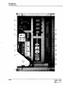
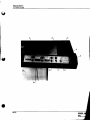
MOD. 923
U.V. CURING
SYSTEM
-
OPERATING
AND
SERVICE MANUAL
I
Dynachem ~chem
U.V. CURING
SYSTEM
NOTICE
PRIOR TO INSTALLING, OPERATING OR PERFORMING MAINTENANCE
ON THE U.V. CURING SYSTEM THIS INSTRUCTION MANUAL SHOULD BE
READ CAREFULLY.
"TO THE BEST OF OUR KNOWLEDGE THE INFORMATION CONTAINED
HEREIN IS CORRECT, HOWEVER, DYNACHEM DOES NOT GUARANTEE
THE COMPLETENESS OR ACCURACY OF THE INFORMATION. USER IS
RESPONSIBLE FOR THE SAFE INSTALLATION AND OPERATION OF THE
U.V. CURING SYSTEM".
Dynachem
U.V. CURING
SYSTEM 24"
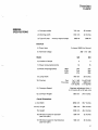
GENERAL
SPECIFICATIONS
1) Conveyor width 710 mm
28 inches
2) Working width
610 mm
24 inches
5000W
5000W
3) Type of Lamp
mercury vapour lamps
Electrical
4) Power type
3 phase; 50/60 Hz; Ground
5} Nominal voltage
380 - 415 - 480
Model
6) Number of lamps
7) Power consumption (kVA)
8) Phase Amperage (Max)
380V
415V
480V
9) Lamp width
10) Cooling
Fan
Flow rate
11) Conveyor Speed:
12) Conveyor Height
922
923
2
3
13
15
34A
31A
27A
37A
34A
29A
760 mm
30 inches
1x1,1kW
2000 m3/h
1177 SCFM
2xO,75 kW
2000 m3/h
1177 SCFM
Stepless adjustment from 1
to 10 m/min (3 to 33 feet min)
950 mm
37.4 inches
*13) Width
2050 mm
80.7 inches
**14) Length
980 mm
38.6 inches
15) Height
1230 mm
48.4 inches
16) Minimum space for operator
(see floor plan)
800 mm
32 inches
17) Minimum space for maintenance
(see floor plan)
500 mm
20 inches
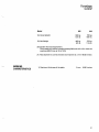
Overall Dimensions
1-1
~hem
U.V. CURING
SYSTEM 24"
Model 922
923
18) Gross Weight
640 kg
1410 Ib
720 kg
15871b
19) Net Weight
440 kg
970 Ib
510 kg
11241b
20) System flow rate requirement.
The exhaust air volume is approximately 900 m 3/h at 3 to 5 m from the
machine (530 Ft3/min at 10 to 15 Ft)
21) Pipe diameter to connect blower and machine is 0.mm 150(6 inches)
WORKING
CHARACTERISTICS
1) Maximum thickness of the plate:
9 mm
0.350 inches
1·2
Dynachem
U.V. CURING
SYSTEM
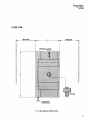
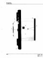
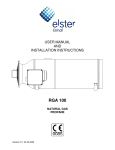
FLOOR PLAN
800 (32")
500
OPERATOR.
*
*
"'" ELECTRICAL CONNECTION *-** See general specification
1·5
Dynachem
u.v. CURING
SYSTEM
WARRANTY
The U.V. curing system is warranted by Dynachem Corporation
against defects in material and workmanship for a period of 90
days, from date of receipt by the customer, during which time Dyna
chem will be responsible for the replacement or repair, at its option,
of any defective parts and for any labor charges connected with the
repair of the U.V. curing system.
Dynachem, for an additional 90 days period, warrants that it will re
place or repair, at its option, any part that proves to be defective; ho
wever, the customer will be responsible for all labor charges during
this additional 90 days period.
Dynachem should be notified in writing of any defect in material or
workmanship of the U.V. curing systelltand if so instructed by Dyna
chem, the U.v. curing system or any part thereof, will be shipped,
freight paid by Dynachem, to Dynachem for repair.
Neither the U.V. curing system nor any part thereof is to be returned
to Dynachem without written authorization from Dynachem.
This warranty is effective only under the condition that the U.V. cu
ring system is installed in accordance with Dynachem specifica
tions.
Additionally, the warranty is null and void if the U.V. curing system is
abused or operated contrary to the instructions or if alterations or
repairs are made by other than authorized Dynachem representati
ves or by written permission from Dynachem.
The warranty for the U.V. curing system does not cover the UV
lamps except for original manufacturing defects reported during the
warranty period.
Dynachem's liability for any breach of warranty is limited, as set out
above, to repair or replacement of the defective part and labor char
ges in certain instances, and in no case shall Dynachem be respon
sible for any consequential damages, nor shall Dynachem's liability
in any case exceed the amount of the purchase price of the U.V. cu
ring system.
This warranty is expressly in lieu of all other warranties, express or
implied, including the warranty of merchantability of fitness for a
particular purpose.
DYNACHEM is a Registered Trademark
1·6 Dynachem
U.V. CURING
SYSTEM
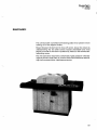
DESCRIPTION
The U.V. curing system has been specially designed for the safe and
fast polymerization of the Ultra-Violet curable products, such as inks
and dry film solder masks currently used in the manufacturing of prin
ted circuit boards.
The wave-length of the U.V. curing system lamps coincides with the
sensitivity curve of most UV curable products thus ensuring fast and
reliable curing.
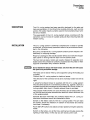
INSTALLATION
The U.V. curing system is delivered complete and is ready to operate
as received. A few and easy operations have to be performed as descri
bed in the following.
Be sure to uncrate the U.V. curing system carefully and to inspect it im
mediately for shipping damage.
Report any damage to the area Dynachem Office and notify the respon
sible carrier in writing within 8 days from the delivery date.
The two mercury-vapour lamps are usually shipped in separate card
board boxes: they should be carefully unpacked and mounted on their
supports underneath lamp reflectors shields.
ICaution: j
Do not handle the lamps with bare hands. Oils from the skin will cause
hot spots and permanent damage.
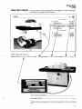
The hood can be easily lifted up and supported using the holding rod supplied. Connect the U.V. curing system to electrical power. The direction of the conveyor belt is set to normally rotate from left to
right.
A powerfull exhaust blower is supplied with the U.V. curing system:
this should be placed in a convenient position (e.g. against a wall on a
suitable support) and connected to the exhaust duct on top of the U.V.
curing system lamp hood. A flexible exhaust hose is provided.
The purpose of this blower is to cool the lamps and to exhaust the ozo
ne from the working area: therefore the warm air should be blown out
of the wor.king place.
Suitable electrical terminals are provided inside the U.V. curing sy
stem and the blower should be connected to them.
Switch on the «Main» switch of the U.V. curing system. This will start
the blower: check the direction of rotation of the blower and reverse
two wires if necessary.
Push «SET UP» button and adjust convejor speed turning the potentio
meter.
Switch on the lamps, one at the time, waiting two minutes among the
lighting of each lamp, in this way you will avoid current rush.
1-7
Dynachem
U.V. CURING
SYSTEM
MAINTENANCE The conveyor belt is provided with lateral guides which prevent it from
running out of the support rollers.
Should however the belt tend to move off center, loosen the rollers by
underscrewing the two allen screws located underneath and move
slightly one side of the roller in question by means of the relative belt
tensioning screw.
The only lubrication required is a small dab of gear grease in roller bea
rings as well as a little chain oil on drive chains this should be done du
ring routine preventative maintenance service.
III-1
~achem
U.V. CURING
SYSTEM
SPARE PARTS ORDERS
To avoid errors when ordering parts, we suggest that the following in
formation be included with the order:
u.v. CURiNG SYSTEM 24"
REF.
DESCRIPTION
Exhaust pipe 0 150{10 mt)
Safety lockable device
ART NUMBER
226-22·302.00
226-22-303-00
226-2(}116-00
22!KlG047.oo
Kindly supply the machine:
Serial number
Q.ty_ _ Ref.
_ _ _ _ Part number ______ Fig. __
Exact shipping address _ _ _ _ _ _ _ _ _ _ _ _~_ _ _ __
Shipping method _ _ _ _ _ _ _ _ _ _ _ _ _ _ _ _ _ __
Orders should be placed with your local Dynachem office or distribu
tor.
IV-1
Dynachem
.
U.V. CURING
SYSTEM
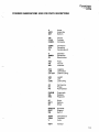
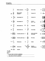
STANDARD ABBREVATIONS USED FOR PARTS DESCRIPTIONS
,,-.
A
ASSY
BOT
Amps
Assembly
Bottom
CIR
CYLN
COMPL
Circuit
Cylinder
Complete
CONN
CTR
CU
Connector
Centering
Centering unit
0
OIMEN
EV
Diameter
Dimension
Electrovalve
FED
HR
INO
Feed
Hot roll
Indicator
JOG
LAM
LAT CUT
Jogging
Lamination
Lateral cutting
LEN
LFT
LUBE
Length
Left
Lubricating
OV
PH
PN
Old Version
Phase
Part Number
PNEUM
REL
REG
Pneumatic
Release
Regulator
RT
SECT
SH
Right
Section
Shore
SPROCK
SUPP
SW
Sprocket
Support
Switch
TEMP
TRNS
V
Temperature
Transport
Volts
VERT
Vertical
IV·2
Dynachem
U.V. CURING
SYSTEM 24"
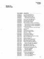
MASTER LIST
ELECTRIC PARTS
PART NUMBER
DESCRIPTION
218-00-001-00
218-00-002-00
218-()()"025-00
218-00-025-01
218-00-025-02
P.C.B. DrIver ESOVAR 53 or 51
GearmotorWEG KGG-613 G13
Emergency stop button assy.
· Red mushroom head 077 EER
· Normal closed contact 077 E01
218-00-026-00
218-00-045-00
218-00-046-00
218-00-047-00
218-20-100-00
Mercury vapor lamp 5000W 760 mm
Ground terminal block EK 16/32
Wire terminal block SAK 4/32
Muffin fan 50/60 Hz 15/18W
Main transformer 8.4 KVA (2° serie) 380V/50 Hz
218-20-100-01
218-20-100-02
218-20-100-03
218-20-101-00
218-20-101-01
· Main transformer 8.4 KVA (2° serie) 220V/50 Hz
· Main transformer 8.4 KVA (2° serie) 415V/50 Hz
· Main transformer 8.4 KVA (2° serie) 480V/60 Hz
Fuse 5 x 20 1A Omega
· Terminal block connection fuse holder SAKS1
218-20-102-00
218-20-103-00
218-20-104-00
218-20-105-00
218-20-106-00
Lamp contactor
Bulb24V
Ampmeter M170 10/5 Pantec
Hozone free UV Bulbs L80-68-H
Capacitor 4 F 1200V
218-20-107-00
218-20-108-00
218-20-109-00
218-20-110-00
218-20-111-00
Main sw 503-110P Breter
3 PH OK light ind 105 DTL 500
3 PH microswitch 114-FT03
Safety line magnetic sw OT (Specify voltage)
Safety 1ry transformer 01
218-20-112-00
218-20-113-00
218-20-114-00
218-20-115-00
218-20-116-00
Auxiliary transformer T1
Safety 2ry coil 220V transformer 02
Safety 2ry coil 24V transformer 03
Safety blowers magnetic sw 04-05
Blower U/HC 182M Utentra 380V/50 Hz
218-20-116-01
218-20-116-02
218-20-117-00
218-20-118-00
218-20-119-00
· Blower LI/HC 182M Utentra 415V/50 Hz
· Blower U/HC 182M Utentra 480V/60 Hz
Safety gearmotor mag. sw 06
Speed adjustment potentiometer
Amperometric transformer TAPK 10/5
218-20-120-00
218-20-120-01
218-20-120-02
218-20-120-03
218-20-121-00
Pilot lamp power on assy (Specity color)
· White head ind 080LSFB
· Red head i nd 080LSFR
· Lamp holder 080ADV
Blowers main contactor Kt,
218-20-122-00
218-20-122-01
218-20-122-02
218-20-122-03
218-20-122-04
Push button assy (Specify color)
Yellow head ind 080PLGG
Green head ind 080PLVG
1 N.O. + 1 N.C. contact 080 B11V
1 N.O. contact 080 B10V
IV-3
J
Dynachem
U.V. CURING
SYSTEM 24"
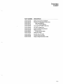
PART NUMBER
DESCRIPTION
218-20-123-00
218-20-124-00
218-20-124-01
218-20-124-02
218-20-125-00
Safety microswitch AZ15ZVR
Switchoff lamps push button assy
· Red head 080PRG
· 1 N.C. contact 080F01V
Hour counter HCM7212124 Vdc
218-20-126-00
218-20-127-00
218-20-128-00
218-20-128-01
218-20-129-00
RC-ARC voltage fi Iter
Diode rectifier bridge KBL04
Relay LY2 12AC
· Socket relay PTF08A
Relay MY2 24AC
218-20-129-01
218-20-132-00
218-20-134-00
Socket relay PYF 08A
Lamps housing handle
Heigh voltage insulation cable
IV-4
Dynachem
U.V. CURING
SYSTEM 24"
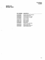
MASTER LIST
MECHANIC PARTS
PART NUMBER
DESCRIPTION
218-02·005-00
218-02·006-00
218-02-007-00
218-02-008-00
218·02-009-00
Conveyor belt 710 mm (4,05 mt)
Chain drive 3/8 x 7/32
Trns roll D 100 x 717· Drive
Trns roll D 60 x 717 • Drive
SprockZ 10318
218·02·010-00
218-02·011-00
218-02·012·00
218-02·048·00
218·22-300-00
Sprock Z 143/8
Sprock Z 24 3/8
Sprock Z 30 3/8
New reflector
Brakets lamps supporting
218·22-301-00
218·22·302·00
218·22·303-00
Ceramic faston sup
Exhaust pipe D 150 (10 mt)
Safety lockable device
IV·5
Dynachem
u.v. CURING SYSTEM
NOTE
ISSU ED 1.0387
REV.
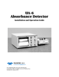
FIG.
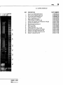
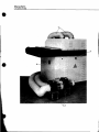
1
U.V. CURING SYSTEM 24"
REF.
1
2
3
4
DESCRIPTION
PART NUMBER
Emergency stop button assy
Lamps housing handle
Main sw 5Q3..110P Breter
Safety lockable device
218-00-025-00
218-20-132-00
218-20-107-00
218-22-303-00
ISSUED 1.0387
REV.
"-------_.
__...
-------
Dynachem
U.V. CURING SYSTEM
.....
IIljllll
NOTE
ISSUED 1.0387
REV.
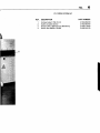
FIG.
2
U.V. CURING SYSTEM 24"
REF.
1
2
3
4
5
6
DESCRIPTION
Safety microswitch AZ15ZVR
New reflector
Brakets lamps supporting
Ceramic faston sup
Heigh voltage insulation cable
Conveyor belt 710 mm (4,05 mt)
PART NUMBER
218·20·123-00
218·02·048-00
218·22·300·00
218-22·301·00
218·20·134-00
218-02-005-00
,
ISSUED 1.0387
REV.
iI;
i
____________________.__ ji
;I
Dynachem
U.V. CURING SYSTEM
,---. NOTE
ISSUED 1.0387
REV.
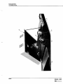
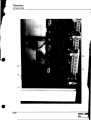
FIG.
3
U.V. CURING SYSTEM 24"
REF.
1
2
3
4
5
6
7
8
9
10
11
12
13
14
15
16
ISSUED 1.0387
REV.
DESCRIPTION
Gearmotor WEG KGG·613 G13
Hour counter HCM7212124 Vdc
P.C.B. Driver ESOVAR 53 or 51
3 PH microswitch 114-FT03
Main sw 503·110P Breter
3 PH OK light ind 105 DTL 500
Safety line magnetic sw OT (Specify voltage)
Auxiliary transformerT1
Blowers main contactor K1
Relay LY212AC
Relay MY2 24AC
Safety gearmotor mag. sw 06
Safety blowers magnetic sw 04·05
Safety 2ry coil24V transformer 03
Safety 2ry coil 220V transformer 02
Safety 1ry transformer 01
PART NUMBER
218-00-002'()()
218-20-125-00
218.()().()()1'()()
218-20-109-00
218-20-107'()()
218-20-108-00
218-20-110.()()
218-20-112'()()
218-20-121'()()
218·20-128-00
218·20-129-00
218-20-117'()()
218-20-115-00
218·20·114'()()
218-20·113'()()
218·20-111'()()
Dynachem
U.V. CURING SYSTEM
t!
•
•
NOTE
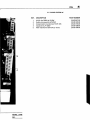
FIG.
4
U.V. CURING SYSTEM 24"
REF.
1
2
3
4
5
ISSUED 1.0387
REV.
DESCRIPTION
Muffin fan 50/60 Hz 15/18W
Safety microswitch AZ15ZVR
Amperometric transformerTAPK 10/5
Capacitor 4.uF 1200V
Main transformer 8.4 KVA (2° serie)
PART NUMBER
218·00-047-00
218-20-123-00
218-20-119-00
218-20-106-00
218-20-100-00
Dynachem
U.V. CURING SYSTEM
•
NOTE
FIG.
5
U.V. CURING SYSTEM 24"
REF.
1
2
3
4
5
6
7
8
9
5
ISSUED 1.0387
REV.
DESCRIPTION
Push button assy (Specify color) Conveyor belt 710 mm (4,05 mt) Pilot lamp power on assy (Specify color) Pilot lamp power on assy (Specify color) Emergency stop button assy Push button assy (Specify color) Speed adjustment potentiometer Switchoff lamps push button assy Ampmeter M170 10/5 Pantec PART NUMBER
218·20·122·00
218-02-005-00
218·20-120-00
218·20·120-00
218-00·025-00
218·20-122-00
218·20-118-00
218·20·124-00
218·20-104-00
Dynachem
U.V. CURING SYSTEM
•
•
FIG.
6
U.v. CURING SYSTEM 24"
REF.
1
2
3
4
DESCRIPTION
Exhaust pipe D 150 (10 mt)
Safety lockable device
Blower U/HC 182M Utentra380V/50 Hz
Muffin fan 50/60Hz 15/18W
PART NUMBER
218-22-302-00
218-22-303-00
218-20-116-00
218-00-047-00
Dynachem
U.V. CURING SYSTEM
'I ?
CN
S
t
11-<
Block connection
R
Male· female
connector
f
~
Push buHon N.O.
T
s
Fe
Fe
E<T
l
)1
Push buHon N.C.
Microswitch N.O.
CA
Microswitch N.C.
F
T
Fc
I?J1=
Proximity switch indo F
Fe
~
Proximity switch cap. L
Ev
{
Electrovalve
~
Electrovalve
Ev
R1
$RE~
Resistor
4.6
t
Column where command is positioned
Page where command is positioned
$
S
Coil of relay
0
Contact N.O.
0
Contact
N.O. + N.C.
+
Condenser
~
~
1
D+
-I>i
Contact N.C.
-(
?
=t*t
RV
C
Fuse holder
AZ
Block connection
fuse holder
RL
-i !!!IIt-:
L
I®®®
Pilot lamp
Switch
Q--~
I
•
I
I
"-----
Rectifier +
cooling system
K~·
Air pressure
gauge
r -- - - --,.
CN:@@@I
L ______ ..J
J
=>
Contact brush +
connector ring
Thermocouple
Temperature
regulator
Tc
Reactance
Z
~
Rc Q
T
K$
IOFF 11
Inductance
RC·ARC voltage
filter
Coil of remote
control switch
Contact N.O.
T
+
11
Contact N.C.
T
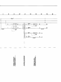
Dynachem
U.V. CURING SYSTEM
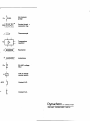
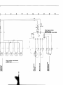
2/314 LAMP· 220f380/4151480V • 50160 Hz
Dynachem
U.V. CURING SYSTEM
®
-
IN
¢
~T
Led
LO-@
m
....
+
AL OUT
T
Air exhaust
ventilator
24Vc.c. Power supply ML
Timer
FC
N.O. contact
FC
~
Block connection
+ led indication
Reed microswitch
1;F1=
Photocell
T
.,1
"
T
SO
SA
S
3tE Transformer
N.C. contact
$
J"UL Flashing alann
~ Buzzer alarm
$
Push button lamp
-I ,
, ii' , ,
~
I I I I I I
-I
R
-~-
I
I
ENe} Antistatic bars
Buffer relays
module
Encoder
<;>----$ Molal
$----$
_+dynamo
Dvnachem
U.v. CURING SYSTEM
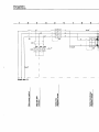
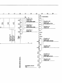
1I
2I
,
3I
6,
5I
2
L1
6mm
2
L2
3
L3
.
S1
9I
8I
7I
,aT
2
' _____ 1
1
25mm2
LS1
R
S
T
Power line
r
-=
...
.c:
(.)
'ji
(,/)
CD
it
0
0
c
'c
:E
.c:
,2»
...
llI:::O
0-;
:::t: ,~
a. "0
CW) .5
.c:
(.)
...CD
E-fi
0::::
'i
-it
,5,~
t!,~
-CD(,/)
~~
CDC)
-cu
~E
~(,/)
->oCU
c
CUC)
-cu
~E
"
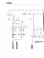
10
I
9
8I
7I
I
11I
13I
12I
15I
14I
2
6mm
2
3
T~
2
4
220V""~1
-[::;:
25mm2
,
I
5
I
7
~
10
3.4
_____ .-,Q2
220V",
3.4
5
l,5mm2
:OT
'------)
24V"'~1
I
L ____
II
...
C1l
E.c:
...
u
o=::
u;~
cl/J
--....
ClSu
>oC1l
_c
C1ltJ)
-CIS
~E
...
...0E
8
24V",
2
1,5mm
-...
c
'0 0
.!
~
NE
0
')(
_c
CIS
~
<C
4.1
8
4.1
:03
.1
C1l
I/J
9
C')
_Na
I/J'
U ...
~C1l
>0
Qiu;
ClSf!!
r.n_
16
I
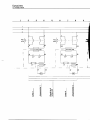
Dynachem
U.V. CURING SYSTEM
,
1
2I
4I
3I
5I
IEJ
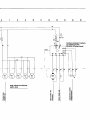
===TA1
--
.
8I
r-----+3
25
1----0----.3. 2
L1
7I
2
...---;2
31
6I
1----/
1-_-+ 26
===TA2
L2
28
27
Al
"
,
"
/
V
.. ..-'
CD
..
CL
E
«I
...I
E
e
~
E
<C
..
..
C"I
Q)
CD
CD
C"I
a....:!::
oc
-::::J
E
=0
C"I
2E
. - «I
E
::::Jo.
0_
0.
«I
...I
0
CD
0.
E
<C
..
C"
...c
=:
e
c:
8I
7
I
13
I
1~
1~
1~
14
I
2
3
1
3
-~ --1
-1
~
"
--l
I
1
1
1
3
3
l.
1
f24
TR2
19
----ll-I_-111---+ 26
C3*
I--_~
73
1-_-+ 20
74
f - - - - I 1--_-10
C4*
___ I
_I
27
33
28
34
76
75
--------------------------~v~------------~/
/
...
-e
N
0.
E
as
.....I
8
:!::I/)
E
C/,)
.:!::
oc
-::J
::Jo.
eE
-as
0_
-e
-
C/,) C/,)
(W)
E
~
'"it
(W)
C/,)
C/,)
...
...
N
(W)
0.
E
as
.....I
'"it
E
oc
-::J
C/,)
:!::I/)
E
.g E
~
C/,) ... =t:
::Jo.
O!!!
E
'"it
0.
E
as
.....I
e
C/,)
0.
E
~
Dynachem
U.V. CURING SYSTEII
1
6
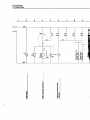
1.15--'=~"-'-=---~4---------------"
2
1.15-'-"'~"-''''--=----..>L-+-----<r-----------''''''1iiii
3
15
16
14
13
-.
I
---(--1 :4.14
4.9
- r - I - r - I - - r + - - !-
-1- -I
L..H--++-+-t--l4.14
5
4.8
Q4
~~-------vr------~/
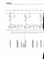
High voltage transformer
muffin fans
)(
oc
.em
'2:5
-
oE
c
0:::1
1
8
9I
10
I
1~
1~
11I
1~
14
I
10 5
t
r-~--
J
4.1:}4.7
-06
56 R1
4.3
16
5
AZ1
I
Driver type comes
starting from:
Serial number 218-01-292
56
10
6
5
7
[>
9
10 8
r--'
11 1
2
3
4
5
16 57 58 59 60 High voltage transfonner
muffin fans
)(
-Or.:
..CIco
er.:
-:;:::
r.:
0:1
oE
...
.s
-
611 62 63 'g
8.
...
0cP
6
E»
'E1ii
cPE
E.2
c:"u
~o
...
00
... ~
COr.:
cPo
-0r.:
:1cP
Dynachem
U.V. CURING SYSTEM
2I
1
I
3
4
5,
I
I
7I
6I
8I
9I
1.15-=-=~--C::----~"""""'f""--------------I~
2
1.15=::....:...-'-----~_+--.....,...----------~
3
Fl
15
2.5mnf
5
14
13
,-
~-+-1 i~~~ - ~--+~~\
4.14
4.9
~__
4.14
4.8
~'-Il' ~~N2
._. _
M2
-I
3
CI)
I:
High voltage transformer
muffin fans
.
.2_
13"2
1»=
I:CI)
Sa.
uE
-~
CI)
I';
.c ...
:i.2
><
--c=el:
01:
.CI~
0=
oE
6I
7I
8I
9I
10
I
13
12
I
11I
1~
14
I
I
16
I
10
5
-t---{-}
144.7
F1
06
56A
R1
16
I
Numbers between brackets
4.3 56
10
are referring to the
.----=.:.;,.:9~-410t-=--~ ESOVAR 53 driver board
5
(2)
(1)
C>
AZl
(3)
(4)
5
6
(10)1~---~
(11)
2----~
(5) (6)(12)3
7
8
5
16
57
58
59
60
P1
High voltage transformer
muffin fans
"C
...o
.o..
-
a)
a)
'0
0. ...
I/) a)
'EQ)
Oc
Co
E>
CJ
"C
Ci)
:;:
c
0::1
co>
a)c
o
--
)(
Oc
--....
..cco
oE
... a)
CJ8
...o
-
:!E
a)E
E.!:!
I/)C
::I
=Co·
4:0.
a)
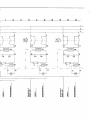
Dynachem
U.V. CURING SYSTEM
2
1
3
41
5
6I
I
7
9I
81
1.
K1
I4.4
06
3.13
4
04
3.2
05
3.5
~
-
'"-y--"
--I
1
l
Ls2
... .:!::::
- .g .g
_J Ls3
. - I/)
2L
...0
--
~
.!!
ii:
0
"C
CD
:::J
lIS
II'
C
a.
«I
II'
0
a::
;:
..c
.5
E«I
... u
lIS
:::IE
: ::Ja.
...c
.~
CD
0
-0
>C
CD
. - I/)
E
E
o.!! o.!!
..c
U
E
:::Ja.
u
lIS
C
C\I
.:!::::
oc ...oc
-:::J -:::J
1
R1
3.13
>
...
«1
CD·
..c"C
.....5
E
...
--
Q;
..c
>
a:
a::
u:.
7
I
,
10
,
9
8,
12
I
11I
K1
0
45
5.1
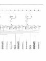
Circuit for 2 .
lamps unit
shunt points 66-68
04
05
3,5
3.2
Circuit for 3
lamps unit
shunt points 67-68
44
~~
I
I
I
15
I
14
I
16I
511 Push button
4,4
06
3.13
1,3
35A
Fcs1
Circuit for 2·3
lamps unit
shunt pOints 37·38
?36
Fcs2
Circuit for 4
lamps unit
?37
Fcs
"-----v----"
Circuit for 4
lamps unit
'-v-'
?38
t-<EMl
~.... :!:
oc
.. =
?38A
C'I
Oc
-=
-=
=""
=""
=c.
=c.
.g e ee
R2
4.6
4.14
E-cEM2
i
39A
)
CN'I
o.!! i:3.!!
8
Circuit for 2
lamps unit
shunt points 4OA·38
5.1
140A
Circuit for 3-4
lamps unit
CN21
1I 39
R2
4.10?
40
D4?:
...
""
c
41
CD
"" 05i
as
3.5
...e
42
CD
.c
>
CD
as
t/)
Circuit for 2
lamps unit
shunt poll'!ts 41·42
3.2
0
---
}
Emergency circuit
line
D~ 3.13 43
Circuit for 3·4
lamps unit
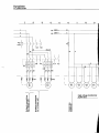
Dynachem
U.V. CURING SYSTEM
2I
1
L
3
4L
6
5
-~~~-k
K2
5.1
I
5.6
8
7I
L
L
L
-----k
I
K3
5.5
5.10
50
48
54
1
9
L
58
56
49
47
K2 22 2.4
5.2
51
K4
2.10
2.12
5.10
K3
2.6
2.8
5.6
3.
,
,
Z
0
.c
(.)
-i
I/)
C.
E
ca
-
....I
I/)
T""
,
V
Z
iT""
-- 0
;c
(.)
...
!.!!
(1)C
CI::l
-gO
-;:: (.)
.0'"
::l
(1)0
-g.c
0 ...
-- _
0
0
o·
T""
0
C
(1)
C
::l
0
...
...::l
(.)
0
::I:
-
.c
(.)
-i
C\I
... .:!::
OC
-::l
:!::I/)
::lc.
_g E
O.!!!
I/)
C.
E
ca
....I
-g
C
C\I
...
C\I
(1)0
:;::C
(.)(1)
(1)
... C (1)::l Cl O -g(.)
"'::l
.0
0
-g
...
(1).c
O::l
-- 0
o_
= ...
-- ...
I
Z
C\I
0
C
(1)
C
::l
0
...
...::l
(.)
0
::I:
0
-
.c
(.)
-i
I/)
E
ca
....I
'E
M
...
M
-=
0
::l
E
U
7
•
8
to•
9
•
•
.s7!.lk
3
5
11
•
12
I
13
I
r
5.14
to
5.13
l52
58
510t-c
51
53
K4
COL3
T
2:10
2.12
5.10
..
N
:;::i
CJ_
ec
G,):::S
c::n O
"OCJ
°C ..
.os
G,).s::.
"85
.- 0
0_
z
N
..
-
..
0
c
G,)
C
:::s
0
CJ
:::s 0
J:
16
I
..)1L-.-JIIK5
llK4
5:10L--J5.9
G,)O
;:c
,
15
14
0-iC'?
0
0
-
:5c
.s::.
CJ ..
CJ
OJ
en
E
as
...I
'E
C'? ,
C'?
.... .:!:
-
oc
-:::s
-en
:::Sa.
2E
O.!!
eo!
G,)C
c::n:::S
0
.... "0 CJ
._
.o:::s
G,)O
"8-:
.- 0
0_
K5
2.14
2.16
5.14
i"llt
:;:0
Z
C'?
0
:;::c
en
"lit
... ::
"0 CJ
._
E
-:::s
.o:::s
:::s
.s::.
.g
J:
"lit
"8-:
0- _0
0
.
.
0
c
G,)
C
.t::.
OJ
:::s
0
CJ
0
CJ ..
CJ
«I
...I
oc
=en
:::Sa.
E
U.!!
eo!
G,)c
c::n:::S
0
.. .. G,)O
"lit
.
-
.
0
c
G,)
c
:::s
0
CJ
:::s
0
J: