1
VACUUM
APPLICATOR
MOD. 724
r
OPERATING
AND
SERVICE MANUAL·:~
I
.~
.
;
Dynachem
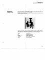
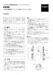
VACUUM APPLICATOR MOD. 724
NOTICE
PRIOR TO INSTALLING, OPERATING OR PERFORMING MAINTENANCE
ON THE VACUUM APPLICATOR MOD. 724 THIS INSTRUCTION MANUAL
SHOULD BE READ CAREFULLY.
"TO THE BEST OF OUR KNOWLEDGE THE INFORMATION CONTAINED
HEREIN IS CORRECT, HOWEVER, DYNACHEM DOES NOT GUARANTEE
THE COMPLETENESS OR ACCURACY OF THE INFORMATION. USER IS
RESPONSIBLE FOR THE SAFE INSTALLATION AND OPERATION OF THE
VACUUM APPLICATOR MOD. 724".
Dynachem
VACUUM APPLICATOR MOD. 724
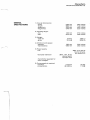
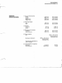
GENERAL
SPECIFICATIONS
1) Over-all dimensions:
- width
-length
· height min.
· height max.
1185
1805
1250
1346
2) Working height:
- min.
- max.
940 mm
1015 mm
37.0 inches
40.0 inches
810 kg
1014 kg
1785 Lb
2235 Lb
800 mm
1000 mm
32.0 inches
39.0 inches
3) Weight:
- total net
· gross
4) Minimum work space:
· operator
- maintenance:
J-
mm
mm
mm
mm
46.5
71.0
49.0
53.0
inches
inches
inches
inches
~\
5) Power supply:
· U.S.
· European standard
480V, 3 Ph, 60 Hz
neutral ground,
9,5 Amps FLC
380V, 3 Ph, 50 Hz
neutral earth,
12 Amps FLC
- Transformer supplied for
other voltages.
6) Compressed air required:
· pressure
· consumption
6 kg/cm 2
28 NLlmin
85 PSI
1 CFM
Dynachem
VACUUM APPLICATOR MOD. 724
GENERAL
SPECIFICATIONS
1) Over-all dimension$:
· width
. length
· height min.
· height max.
1185
1805
1250
1346
2) Working height:
-min.
. max.
940 mm
1015 mm
37.0 inches
40.0 inches
810 kg
1014 kg
1785 Lb
2235 Lb
800 mm
1000 mm
32.0 inches
39.0 inches
3) Weight:
- total net
· gross
4) Minimum work space:
- operator
- maintenance:
mm
mm
mm
mm
46.5
71.0
49.0
53.0
inches
inches
inches
inches
~-';
5) Power supply:
· U.S.
- European standard
480V,3 Ph, 60 Hz
neutral ground,
9,5 Amps FLC
380V, 3 Ph, 50 Hz
neutral earth,
12 Amps FLC
- Transformer supplied for
other voltages.
6) Compressed air required:
- pressure
- consumption
._-,
6 kg/cm 2
28 NUmin
85 PSI
1 CFM
Dynachem
VACUUM APPLICATOR MOD. 724
WORKING
CHARACTERISTICS
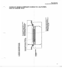
1) Dimensions of the chamber:
2) Suggested dimenSjions of the
panel:
-width max.
· length max.
· thickness min.
· thickness max.
--~\ 650 x 650 mm 25.5 x 25.5 inches
6'10 mm
610 mm
0.4 mm
3.4 mm
24 inches
24 inches
0.016 inches
0.134 inches
Dynachem
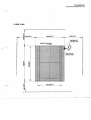
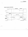
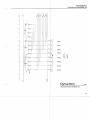
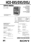
VACUUM APPLICATOR MOD. 724 FLOOR PLAN 500 (20")
PNEUMATIC
CONNECTION
ELECTRICAL
985
Dynachem
VACUUM APPLICATOR MOD. 724
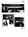
VACUUM APPLICATOR
MOD. 724
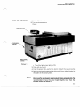
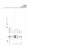
DESCRIPTION
The Vacuum applicajtor mod. 724 is a semi-automatic machine desi
gned to ensure com~lete elimination of air from the surfaces of a prin
ted circuit board that has been laminated with dry film solder mask.
Complete encapsulation of the circuit conductors and intimate con
tact of the solder mal,sk film to the surfaces is achieved by using va
cuum technology, heiat and mechanical pressure.
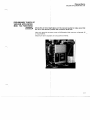
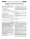
The Vacuum applicator mod. 724 machine consists of two heavy alumi
nium platens that are situated vertically above one another during the
vacuum cycle (diagram 1). The lower platen is movable for loading with
circuit boards that have solder mask film applied.
The upper platen has a blanket of reinforced silicon rubber stretched
across the lower surface forming a ceiling for the vacuum chamber.
This blanket forms a: diaphragm which provides the mechanical pres
sure at the end of the vacuum cycle.
The lower platen consists of a «well)) which is the working area.
A silicon rubber gasket around the circumfrence of the platen forms
the vacuum seal when the platens are closed. Air is evacuated through
channels around the perimeter of the «well)).
Both platens contain temperature controlled heaters.
To accommodate the wide variety of panel thicknesses the Vacuum
applicator mod. 724 is supplied with shim inserts to adjust the panel to
the correct height in the «well» of the bottom platen.
The Vacuum applica~or mod. 724 has been designed for easy operation
and maintenance. Th~ electrical components and microprocessor that
control the system ajre housed in an enclosure that is easily accessi
ble.
Two side panels are removable to provide access to the vacuum pump
system. The control panel contains all the commands and adju
stments required for operation of the machine.
SAFETY
Emergency stops an~ located on each corner of the machine for easy
access by the operatpr. A folding type guard is fixed to the bottom pia·
ten for operator safety and to prevent objects from falling Into the rna·
chine area.
The Vacuum applica~or mod. 724 is available in 24 inch (610 mm) and
30 inch (762 mm) plaiten sizes.
1-1
...~
zftt
....
Dynachem
VACUUM APPLICATOR MOD. 724
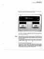
VACUUM APPLICATION
PROCESS CYCLE
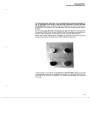
Printed circuit boards that have dry film solder mask applied to one or
both sides are vacuum processed in the following sequence.
• The panel(s) is pla¢ed on the lower heated platen (diagram 2).
• The lower platen i$ driven beneath the top heated platen and is mo
ved upward to seal the chamber and start the vacuum process cycle
(diagram 3).
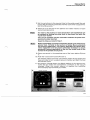
• At the end of the first stage of vacuum there is a second stage or
«slap down» of the top blanket to apply m6chanical pressure on the
circuit board to force the solder mask film to conform around the cir
cuit conductors (diagram 4).
• When the cycle iSi complete the vacuum is released and the lower
platen returns to t~e start position to be unloaded and loaded for the
!
next cycle.
1-2
......
.b..
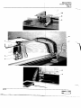
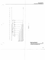
Shim material
-stIit:orr rubberlnsert
1.Smm
Upper platen
To VACUUM pump
"We".. formed in lower platen
VACUUM pump
)
7
•
....
mbly
..~_Seal
lower heater assembly
.......... ................ , .. "' ..... "' .... ..,<0;11 ....
(I)
(I)
Z
::D
:IE
m
o
r
Qo
::D
m
."
."
-t
::c
m
e
-to
m."
;:r:.(I)
."Z
r--t
~m
NZ
........ ."
0
00
3:n
03:
::Dc:i)
OZ
~~
C::c
no
"'(1)
."n
;:r:.
n ::c
em
e3:
3:~
;:r:.n
<
)
i~
~~
0::r
a~
~o
-0
~c:
c:
,..3:
......
cJ,
)
Panel to be processed must be level with or
sughtly below the shoulder of the lower
platen for best results.
)
Heater a
z:
m
-t
l>
r-
""t'I
=
::e
m
0
r
=
0
"TI
r-
l>
-
en
-t
c
m
C)
z:
en
:::c
3:
3:
C)
z:
::e
0
en
:::c
C"')
-t
l>
en
C"')
:::c
m
3:
)
~3
!='(I)
!i
r
"'tI
"'tI
>
i:
~
c:
c:
Dynachem
VACUUM APPLICATOR MOD. 724
PNEUMATIC CONNECTIONS
The compressed air Supply (shop) to the Vacuum applicator mod. 724
should be a minimum of 85 PSI (6 bars).
Connect an air line t9 the air supply fitting and adjust the pressure re
gulator to 58 PSI (4 *ars).
/
i
Check the oil level i1 the air filter assembly and check to sight glass to see that the air lubri<J;ation is adjusted to 1 to 2 drops of oil every 10 cy
cles. Use one of thelfollowing when additional oil is needed: I
ESSO
BP
SHELL
MOBIL OIL
TEXACO
GULF
AROX EP15
ENERGOL R0505
TORCULA OIL 32
MOBIL MISLUB 27
ROCK ORIL LUBE X5W
GULFSTONE 15
1-10
Dynachem
VACUUM APPLICATOR MOD. 724
PRELIMINARY CHECK OF
VACUUM APPLICATOR
MOD. 724 FUNCTIONS
ICaution:
I
Check the oil level si9ht glass on the vacuum pump to make sure that
the oil in the pump i, above the minimum level line
Use only special
or equivalent).
vac~um
pump oil (Edwards high vacuum oil grade 15
Maximum tank capafity is 5.3 quarts (5 liters) .
.~.
l-11
- - - - - - -....................-~......~
-----------'---------------~---'-------
Dynachem
VACUUM APPLICATOR MOD. 724
Adjust the air pressure to 58 PSI (4 bars).
Check to see the vacuum controller 503 ON/OFF power switch is in the
{{ON» position.
The controller must display a pressure in mbar close to atmospheric
value (1.1 x 10³ mbar).
If the display is other than atmospheric value, turn off the «main
switch» of the Vacuum applicator mod. 724 and back to «ON» again.
The display should now be 1.1 x 10³ mbar.
INote:!. The controller 503 has already been calibrated to atmospheric value.
For any further calibration or display information refer to the manufac·
tures instructions included in the maintenance section of this manual.
1-12
-
........
--.~---
..
-~ ......~--
..
-~......~-------------------------~------
Dynachem
VACUUM APPLICATOR MOD. 724
PRELIMINARY START-UP When the machine is put on by means of its yellow breaker, the machi·
PROCEDURES ne will signal this condition through the lighting of the POWER ON pi·
lot lamp. The alphanumeric visualizer will signal the date and time for
about 3 seconds, and after it will visualize the texts n. 1 and 4. When no
irregularities are detected, the visualizer will scan OK's for any compo·
nent checked during the check·list control. When, however, one or mo·
re drawbacks should be already present when the machine is put on
(f.i. lacking of compressed air, open protections, etc.) these will be vi·
sualized one at the time, i.e. sequentially (after removal of first, the se·
cond will show ...) until they could be entirely eliminated.
On the visualizer some command to be carried out will be shown and,
when necessary, it will be possible select the operator's guide through
the selector PRELIMINARY INSTRUCTIONS. When this selector
should not be activated, the visualizer, after the initial messages, will
show only the date and the time, but it will remain ready for emitting
any alarm and diagnostic message.
-\
[·13
Dynachem
VACUUM APPLICATOR MOD. 724
For starting up the machine, or for restoring the machine operation af·
ter an emergency occurred, it will be only necessary to press the SET
UP pushbutton; then, provided that the machine is not on the end·of·
cycle step, the set·point will be effected and the stored alarms will be
erased.
By actuating the SET·UP pushbutton the thermoregulator «temperatu·
re control UPPER PLATE and LOWER PLATE» displays will light and it
will be than necessary to set again up the working temperature.
When the preset temperature of tables is reached, the vacuum pump
could be activated through the START PUMP pushbutton.
It should be to note that the pushbutton STOP PUMP, which is to use
for stopping the pump, is enabled only when the movable table (the 10·
wer one) is on «fully out» position, i.e. when the machine is at the end
of cycle.
{·14
Dynachem
VACUUM APPLICATOR MOD. 724
Through the three numeric selectors CYCLE TIME, on the control pa
nel, it is possible to preset the time in seconds, that is the lenght of ti·
me during which both the plate and D.F.S.M. are submitted to air eva
cuation.
Inside the panel there are another two numeric selectors which select,
in seconds, the SLAP DOWN TIME, that is the lenght of time during
which the machine exerts a pressure on film and plate; these could be
selected only by an authorized engineer.
By pressing the CYCLE pushbutton, after the PCB and the respective
film are put on the movable table, this table travel to the other end of
the machine and then is raised and goes fitting to the upper table.
The scanning of the cycle time begins, and after will follow the slap
down, the subsequent lowering of the table and its return to the origi·
nal position with the operated plate.
During the whole cycle, including all movements, all the components
(electro-valves, sensors, protection, etc.) are costantly watched and,
should any irregularity occur, the machine is stopped and the respecti
ve alarm is visualized as per the enclosed list.
Therefore, if, for instance, after starting through the pushbutton CY·
CLE the movable table does not move, after a few seconds are elap·
sed, the machine is emergency stopped and on the alphanumeric vi·
sualizer the message ,«HORIZONTAL TRANSLATION IS FAILED» will
appear.
1-15
Dynachem
VACUUM APPLICATOR MOD. 724
In the same way, if the lower table raises but does not act on the end
of-stroke upper sensor Fc4, or acts on it but this does not move, the
machine is emergency stopped and on the alphanumeric visualizer the
message «SEN. Fc4 DAMAGED)) will appear.
Special care has been devoted to the members which are charged of
safety and accident prevention. Actually a movable guard prevents any
access to the upper table and could emergency stops the machine.
If the upper table should be raised, it is first necessary unscrew the
stop screws and with such a condition the machine cannot be opera
ted.
Only when the voltage is off it is possible to access to the control pa
nel; all external components put under tension are fully protected by
proper guards and are grounded.
In any moment of the cycle, by pressing one of mushroom-head pu
shbutton the machine will be immediately stopped and all electric
component external to the control board, will be put off, but the alpha
numeric visualizer and the vacuum device.
The machine can be reactivated, so automatically effecting the set
point, when the SET UP pushbutton will be pressed another time.
The illuminated pushbutton CYCLE is also used of confirming to the
microP that the order it put out (as presetting the table temperatures,
ecc.) has been carried out.
This is only valid when operating under the «guided modell, i.e. when
having operated the selector «PRELIMINARY INSTRUCTIONS)}.
The thermoregulating systems of the upper and lower table are entirely
electronic ones and they do not require any maintenance; anyway it
should be suitable to periodically control the correct operation of for
ced ventilation systems, both on the control panel and of the vacuum
pump.
The electrovalves are equipped with DC solenoids and therefore are
not related to the frequency, whi Ie the solenoid switches can operate
both with 50 and 60 Hz.
For all component related to the fully machine operation have been se
lected those with a very long life, but anyway the lubricant levels of the
vacuum pump should be periodically checked.
Although all solutions for diagnosing the machine alarms have been
studied, it is however possible to obtain more informations, in case of
f~iI~rVl
consultinij the enclosed electric diawrams.
br
1·16
Dynachem
VACUUM APPLICATOR MOD. 724
ICaution: •
THE ALARMS REMAIN STORED EVEN IF THEY HAVE A VERY SHORT
DURATION, FOR PREVENTING OF HAVING THE MACHINE EMER·
GENCY STOPPED WITHOUT KNOWING THE REASON OF FAILURE.
IN ANY CASE THE ALARMS WILL BE ERASED, WHEN NO LONGER
EXISTING, THROUGH THE SET·UP PUSHBunON.
Prior to committing the Vacuum applicator mod. 724 to production it is
recommended to run the machine for 10 to 24 continuous hours with
the heat and vacuum «ON)) and the platens in the closed, sealed posi·
tion.
This «conditioning)) will help assure good vaccum application of the
solder mask film by removing any moisture and dust from the chamber
as well as equilize the heavy aluminium mass of the platens.
To put the machine into a continuous running mode it is necessary set
at zero the «cycle time)) thumb wheels.
r~!~~!~~l Disconnect the main power supply before servicing the Vacuum appli·
cator mod. 724.
A mechanical lockout Is recommended to prevent accidental powering
up to the machine.
[-17
--~-
...-
-....- -..--....- -...- -...- -...- -... - - - ....
~-
--
----
-~----------.
----~
Dynachem
VACUUM APPLICATOR MOO. 724
OPERATION SAFETY
1) Operation of the Vacuum applicator mod. 724 requires attention to
safety with respect to both the mechanical functions of the machine
and the chemical properties of the dry film.
2) Refer to the Dynachem technical data included in this manual «A
Guide to the safe handling and use of laminar products)).
3) Avoid contact with the aluminium platen frames when they are hea
ted to operating temperatures. The surface temperatures are in the
range of 150 to 180 ° F (66 to 82 0c).
WARNING!
4) Disconnect and lockout the main power supply before opening the
access panel doors to make adjustments or servicing the Vacuum
applicator mod. 724. A mechanical lockout is recommended to pre·
vent accidental powering up of the machine.
II·1
Dynachem
VACUUM APPLICATOR MOD. 724
START UP SEQUENCE
1) Switch «ON» the main power
2) Turn the air pressureon
Check:
Operating area
Air pressure
regulator
Picture 1
• The white light «main light» is ON.
3) Push «set up» button
4) Push the green light "pump ON» button to start the vacuum pump
and platen heaters.
5) Select and place the appropriate shim and silicon rubber blanket in
the «well» of the bottom platen.
The top of the panels to be processed should be approximately the
same level as the shoulder of the bottom platen (Illustration I) it is
recommended to have the panel height slightly lower than the
shoulder rather than above it.
II·2
Dynachem
VACUUM APPLICATOR MOD. 724
6) Set the top and bottom temperature controls to the values recom
mended for the dry film solder mask being used.
For laminar DM dry film solder mask the typical platen temperatu
res would be 170-200"F (77-93"C) for the top and 150-180"F (66
82°C) for the bottom platen.
INote:1 Typically there is a variation of approximately 15°C (60°F) between
the control setting and the surface temperature of the silicon rub
ber inserts. This differential is due to the heat transfer loss through
the silicon rubber.
The temperature controls should be set to allow for this variation,
in 9~,r 19 ,IIpln lh, r,n~1 ,~rlace temrerature recommended for
the solder mask 'ilm being processed.
The use of Oynachem ccthermolabel" temperature strips is recom·
mended (set 2 140 to 180°F· 60 to 80°C). The strips should be
placed on both sides of a test panel which is then run through a
normal vacuum cycle. For laminar OM, the typical panel tempera
ture should be in the range of 150·170oF (66·nOC).
11-3
-
Dynachem
VACUUM APPLICATOR MOD. 724
7) Set the cycle timer to the required time for the solder mask film and
type of PC panel being processed. Normal cycle time is approxima
tely 50 to 60 seconds.
8) Allow 10 to 15 minutes for the platens and rubber inserts to reach
operating temperature.
The time for the platens to reach temperature and equilibrium can
be reduced by turning the cycle timer to maximum and push the
((cycle start» button.
This can be repeated until the controllers indicate the preset tem
perature has been reached.
Reset the times as noted in Step 7.
Before proceeding to process production panels in the Vacuum ap
plicator mod. 724 refer to the section on Solder Mask Lamination
and Vacuum Application. This section describes the various lami
nation equipment and the proper lamination technique to assure
successful vacuum application of the dry film solder mask to the
surface of the printed circuit paneL
9) Place one panels in the operating area of the lower platen (Picture
1).
10) Push the «cycle start» button (Picture 1).
The bottom platen will move into position under the top platen and
they will close to form a sealed vacuum chamber and start the heat
and vacuum cycle.
11) As vacuum is being drawn the digital readout of the vacuum con
troller 503 will reflect the atmospheric conditions in the vacuum
chamber. When the correct vacuum is reached the controller
should display approximately 2.0 mbars.
II-4
Dynachem
VACUUM APPLICATOR MOD. 724
12) At the end of the first stage of vacuum the chamber is opened to at
mosphere causing the top rubber diaphram to move downwards
and ((slap down» on to the panel. This mechanical pressure causes
the solder mask resist to conform around the circuit traces.
The ((slap down time is adjustable» (see trouble shooting figure)
and will vary from 2 to 10 seconds depending on the size of the air
emittance valve used, the type of soldermask dry film and the con·
figuration of the printed circuit panel.
13) When the total cycle is complete the platens will open and the bot
tom platen will return to the loading position ready for the next cy
cle.
ICaution: •
The platen and processed panel are hot. Handle with care to avoid
burns.
If the processed panel has any defects such as uresist wrinkles» or
««air entrapment» around the circuit traces refer to the trouble shoo·
ting section.
::1" ;"'\
A
j~
> ,
...
. .
'
.
Minimum vacuum re1uired for slar down action
11·5
- - - _ .............-
-
...
~
... ~~~-
Dynachem
VACUUM APPLICATOR MOD. 724
TROUBLE SHOOTING GUIDE PROBLEM
1) PROBABLE CAUSE
SOLUTION
2) PROBABLE CAUSE
SOLUTION
PROBLEM
1) PROBABLE CAUSE
SOLUTION
2) PROBABLE CAUSE
SOLUTION
3) PROBABLE CAUSE
SOLUTION
THE VACUUM APPLICATOR MOD. 724 DO NOT SWITCH ON. F1 or F2 fuses burn out.
Replace it.
Emergency push button defective.
Replace it.
THE PUMP DO NOT ROTATE. Thermaloverload is off. Reset it and check power consumption. Thermaloverload defective.
Replace it.
Motor pump burnt out.
Replace it.
IIl-1
•....1
Dynachem
VACUUM APPLICATOR MOD. 724
PROBLEM NO VACUUM APPLICATOR MOD. 724 ON THE APPLICATION CHAM·
BER.
1) PROBABLE CAUSE
SOLUTION
F5 or F6 fuses burn out.
Replace it.
----~
2) PROBABLE CAUSE
SOLUTION
EV6 or EVa not functioning.
Replace fuse inside at the electrovalve.
PROBLEM «SLAP DOWNII CYCLE NOT ACTIVATE.
1) PROBABLE CAUSE
SOLUTION
2) PROBABLE CAUSE
SOLUTION
3) PROBABLE CAUSE
SOLUTION
----
The top rubber blanket is torn.
Replace it.
Preselection slap down time is zero.
Set approximately a -:-12 seconds.
-----------------
EV7 not functioning.
Check fuse if necessary replace it.
PROBLEM HEATERS ELEMENT NOT FUNCTIONING.
1) PROBABLE CAUSE
SOLUTION
2) PROBABLE CAUSE
SOLUTION
F3 or F4 fuses burn out.
Replace it.
Temperature regulator defective.
Replace it.
-----------~
3) PROBABLE CAUSE
SOLUTION
4) PROBABLE CAUSE
SOLUTION
--------
Mil spec connector defective.
Check wires connection.
Heater element burnt out.
Replace it.
1II-2
Dynachem
VACUUM APPLICATOR MOD. 724
PROBLEM
1) PROBABLE CAUSE
SOLUTION
2) PROBABLE CAUSE
SOLUTION
3) PROBABLE CAUSE
SOLUTION
WRONG PROCESS APPLICATION. Wrinkles on surface.
Pay attention at the prelamination. Must be cold and without pressure
facilitating air exhaust from the sandwich in the vacuum application.
Spot in the surface without solder mask.
The temperature is too. much heigh; please decrese in accordance at
the film specifications.
Air entrapment.
Prelamination not proP'rrly carry out.
Not sufficient «SLAP DOWN)) time.
Temperature less than
4) PROBABLE CAUSE
SOLUTION
film specification.
Solder mask not coveri~g islands and traces because is split out.
«CYCLE TIME" and «SLAP DOWN» time longer than we suggested:
50..;.. 60 seconds cycle time - 8 12 seconds slap down time.
III-3
Dynachem
VACUUM APPLICATOR MOD. 724
STARTING MESSAGES 1 - Vacuum applicfiltor mod. 724 for DFSM application by Dynachem
4 - If you need, activate «Preliminary instructions»
7 - When starting push «Set Up» button, please
10· PLS, confirm my questions by ((Cycle» pushbutton
13 - Set cycle time & temp.·1 00 C max. - Did you do this?
16· Are plates in selected temp.?
19 - Start pump
21 - Put board and push ((Cycle» button
24 - Cycle started
25 - Lower plate IN
27 - Lower plate UP
29 . Air exhaust
30 . Slap-down
31 - Vacuum release
32 - Lower plate down
34 - Plate move back
36 - Cycle-ended
38 - No slap down
III·4
Dynachem
VACUUM APPLICATOR MOD. 724
DIAGNOSTIC AND
CHECK MESSAGES
WHEN «ALARM»
IS «ON))
..~.
40 - Check-control 42 - Emergency 43 - Pump overload 44 - Top plate opened 46 - Vacuum not reached 48 - Safety guard off 51 - lAir pressure low 53 - Cycle microswitches malfunction 56 - Emergency OK 57 - Vacuum pump OK 58 - Top plate closed 59 - Vacuum alarm OK 60 -Safety guard OK 62 - Set-point - - 63 - Sens. FC3 damaged
65 - Horizontal translation is failed
67 - Sens. FC4 damaged
69 - Vertical translation is failed
71 - Sens. FC5 damaged
73 - Sens. FC2 damaged
III-5
Dynachem
VACUUM APPLICATOR MOD. 724
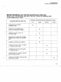
MAINT~NANCE OPERATION
SWITCH OFF THE MACHINE AND WAIT FOR ALL PARTS IN TEMPERATURE
TO BE COMPLETELY COLD
BEFORE PROCEEDING ANY FURTHER
PERIODIC MAINTENANCE RECOMMENDED EVERY:
VACUUM APPLICATOR 724
DAY
CLEANING OF SILICONE
RUBBER SHIMS
WEEK
MONTH
YEAR
•
CHECK UP ON LUBRICATING
LEVEL OF PNEUMATIC CIRCUIT
•
CHECK UP ON OIL LEVEL OF
VACUUM PUMP
•
REMOVE ANY LAMINATION FUMES
COI\lDENSATE FROM THE PROPER
BOX
•
I
GENERAL COMPLETE CLEANING
•
CHECK UP ON OIL LEVEL OF GEAR
- UPPER PLATEN (730)
•
LUBRICATION OF ROLLER GUIDES
,
- LOWER PLATEN
•
LUBRICATION OF LATERAL GUIDES
FOR FOLDING GUARD
•
CHECK UP ON WEAR CONTACTORS
ELECTRICAL PANEL
•
I
•
III-6
--/~\
VACUUM APPLICATOR MOO. z
o
~
11 DYNACHEM
~
~-------------------
Dynachem
HOW TO ORDER SPARE PARTS
VACUUM APPLICATOR
MOD. 724
HOW TO ORDER SPARE PARTS
To avoid wastage of time and mistakes in delivery. it is strongly recommended that SPARE PARTS should be ordered in accor
dance with the example given below. Write the following details aiearly and correctly:
-Serial Number
-Manufacturing Year
-Figure Number
-Position Number
-Code Number
-Denomination
-Quantity
-Exact address
-Means of dispatch
MORTON INTERN~TIONAL S.p.A. DYNACHEM ELECTRONI~ MATERIALS - ITALY VIALE LOMB~RDIA, 52 21040 CASTRONNO i (V ARESE) ITALY TEL. (0332,893190 TELEX 31)1268 FAX (0332) 892153 ABBREVIATIONS USED IN THE SPARE PARTS CATALOGUE
L.H.-Left hand
R.H.-Right hand
INF-Lower
SUP-Upper
ANT-Front
POST-Back
C R-Quantity as requ ired
I\JF-Not supplied
R I F-Reference only
NOTE
DATA CONTAINED IN THIS PUBLICATION ARE NOT BINDIING. WE RESERVE THE RIGHT TO MAKE ANY MODIFI
CATIONS DEEMED NECESSARY WITHOUT PRIOR NOTICE
Dynachem
VACUUM APPLICATOR
HOW TO OROER SPARE PARTS
MOD. 724
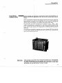
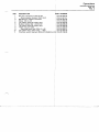
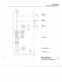
Dynachem
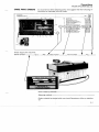
INSTRUMENT PANEL AND CONTROLS
VACUUM APPLICATOR
MOD. 124
TAB. 6
REF.
PART NUMBER
OESCR IPTION
1
015-20-104-00
PILOT LAMP ASSY
2
015·00·022-00
PUSH-BUTTON ASSY (SPECIFY COLOR)
3
015·20-107·00
015-20·101-00
015-20-105-00
015-00-023-00
015·22-427-00
015-22-399·00
015-22-427-01
015·22-427·02
015·22-428-00
015·22·412·00
015·22-454·00
015·22·424-00
015·22·432·00
015·22·433-00
015·20·100·10
01522·452-00
01 5-20-120-00
015-22·453·00
015-20·102-00
STOP PUMP PUSH,BUTTON ASSY
THUMB WHEEL 3 DIGIT T56 ASSY
SELECTOR SWITCH ASSY
EMERGENCY STOP BUTTON ASSY
LOWER SUPPORT FOR MEASURES INSTR. 15133
SCREW TCEI M5 " 10
KNOB M5 x 20
PINd.5x 10
UPPPER SUPPORT FOR MEASURE INSTR. 151~4
SCREW TCEI M4 x 20
LOWER BOX COVER 15142
SCREW TCEI M5 x 12
BOX FOR MEASURE INSTRUMENTS 15140
REAR BOX COVER 15141
CONTROLLER MOD. 503 EDWARDS
SCREW TSTC M3 x 10
ALPHANUMERIC DISPLAY DAA 144 F3
ALUMINIUM ANODIZED PANEL
TEMPERATURE REGULATOR E5C4·Q4D-J-DIN
4
5
6
7
8
9
10
11
12
13
14
1F;
16
17
18
19
20
21
[/
[/
[/
I
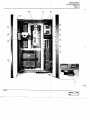
Dynachem
INSTRUMENT PANEL AND CONTROLS
VACUUM APPLICATOR
MOD. 124
TAB. 6
16
f9
y_11
9
...I
jrn-
rr'il~
10
,,&-8
----------~-----~---~-------------.~ .. -~.~
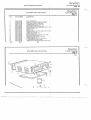
Dynachem
INDEX
.~
-
- -..
...........
---~~
TAB.
1
BASE UNIT
TAB.
2
PLATENS
TAB. 3
LOWER PLATEN SUPPORT
TAB
VACUUM SYSTEM
4
TAB. 5
AIR SYSTEM
TAB. 6
INSTRUMENT PANEL AND CONTROLS
VACUUM APPLICATOR
MOD. 724
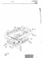
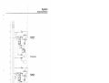
Dynachem
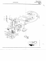
BASE UNIT
VACUUM APPLICATOR
~OD. 724
AB. 1
Z
1
~·-29
34 I 35 I
36
%~
&fP
®-4
pOID
OF VIEW Dynachem VACUUM APPLICATOR
MOD. 724 BASE UNIT
TAB. 1 .~
REF .
PART NUMBER
DESCRIPTION
1
2
3
4
5
6
7
015-02-054-00
015-02-054-01
01 5-02-054-02
015-02-054-03
015-02-054-04
015-22-331-00
015-22-331-01
LEVELING FEET ASSY 15096 LEVELING FEET 15095 NUT M16 CIRCLIP d. 16 THREADED ROD M16 x 150 RIGHT DOOR SASH FRAME 0138.0~.006
HINGED CONNECTION
I
8
9
10
11
12
13
14
15
16
17
18
19
20
21
22
23
24
25
26
27
28
29
30
31
32
33
015-22-331-02
015-22-390-00
015-22-331-03
015-22-332-00
015-22-333-00
015-22-385-00
015-22-386-00
015-22-309-00
015-22-334-00
015-22-335-00
015-22-336-00
015-22-337-00
015-22-387 -00
015-22-455-00
015-20-109-00
015-22-389-00
015-22-391-00
015-22-392-00
015-22-338-00
015-22-308-00
015-20-108-01
015-22-340-00
015-22-438-00
015-22-394-00
015-22-341-00
015-22-342-00
SCREW TCEI M6 x 10 WASHER d. 6,4-12,5 SCREW TSTC M5 x 20 PLATE FOR BREAKER FIXING 1512!7 LEFT DOOR SASH FRAME 0138.00.[005 LEFT LOCK 440
'
RIGHT LOCK TOP END FRONT PLATE 15119 LEFT LOWER COVERING DOOR 01t38.00.003 BASIC PLATE SUPPORT 0138.00.0Q7 I
LEFT SHOULDER 0138.00.010
UPPER LEFT CRANKCASE 0138.00i008 SCREW TE M12 x 30 WASHER d. 13-24 PROXIMITY SWITCH 3RG-4012-0ABOO (012 mm) SCREW TE M6 x 15 NUT M6
CHAIN (GENOVESE)
TIE-ROD 15038 TOP END PLATE REAR 15152 PROXIMITY SWITCH 3RG-4013-0ABOO (018 mm)
UPPER RIGHT CRANKCASE 0138'1,009
SCREW TCEI M8 x 20 I
WASHER d. 8,4 x 17 I
RIGHT SHOULDER 0138.00.011 TRANSPORT BLOCKING DEVICE 15120 34
35
36
37
38
015-22-343-00
015-22-395-00
015-22-396-00
015-22-344-00
015-22-355-00
39
40
41
42
43
44
45
46
47
015-22-435-00
015-20-124-00
015-22-399-00
015-22-356-00
015-22-357-00
015-00-071-01
015-00-071-02
015-22-358-00
015-22-330-00
THROTTLE LOCK 15124 LOCK
KEY
COVERING PLATE 15156 LATERAL BRACKET FOR LOCK 15 25 I
I
SCREW TE M5 x 10
GROUNDING CABLE
SCREW TCEI M5 x 10 HINGE 013800.012
RIGHT LOWER COVERING DOOR 0138.00.004
EXHAUST FAN W25 107-AA01-40
SAFETY FINGERS GRATE
BASIC FOOT 0138.00.001
FRAME 0138.00.002
i
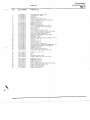
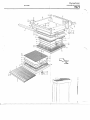
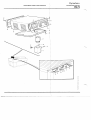
Dynachem
PLATENS
VACUUM APPLICATOR
MOD. 724
TAB. 2
,i
43
~INT
OF
VIEW
<:
~
([
ii'
Dynachem
PLATENS
VACUUM APPLICATOR
MOD. 724 TAB. 2 REF.
PART NUMBER
DESCRIPTION
015·22·312·00
BRACKET FOR FOLDING GUAR9 FIXING 15139 2
015·22·313·00
BRACKET FOR FOLDING GUARd FIXING 15138 3
015·22-424·00
015·22-436·00
015·02·081·00
015·22·403·00
015·22·317·00
015·02·011·00
01522·318·00
015·02·076·00
SCREW TCEI M5 x 12 FLAT WASHERd. 5,3·10
.
FOLDING GUARD LOWER PLATE'" 15153 I
SCREW TSPC M4 x 10
LOWER ALUMINIUM PLATE 3804t SEALING GASKET 15057 i
LOWER GRAPHITE SPACING
HEATER RETAINING PLATE 8 m~ (0.315") 15050/A HEATER 1000 W LEFT 15111 4
5
6
7
8
9
10
015·00·012·01
12
"
or
13
14
15 16
17
18
19
20
21
22
23
24
25
26
27
28
29
30
31
32
33
34
35
015-02·077 ·00
1015.02-009.00
015·02·082·00 .1015-02·078·00
015·22·319·00
015-22·398-00
015-02·062·00
If'
015·02·079·00
015-22·320·00
015·00·012·00
015·22·321·00
015·22·322·00
015·22·323·00
015·22·307·01
015·22·324·00
015·22·325·00
015·22·326-00
015·22-450·00
015·22·310·00
015--22·327-00
015·22456·00
015·22·437·00
015·02·06()'01
015-02-060·00
HEATER RETAINING PLATE 3 m,ir (0.118")
15051/A
.
RUBBER SHIM BLANKET BaTT. 1f6 mm (0.63", RUBBERSHIMBLANKET660x66qx3mm
RUBBER SHIM BLANKET 660x660x4 mm ~
:6'~~~N~~~ ~s~ Io0R SCR EWS 5151
1
ro'';11S- o-:;t 004-0'
0 :l RUBBER BLANKET FRAME· TOP i15032
RUBBER BLANKET TOP.REINF01·CED 1.6 mm ....
(0.63") ALUMINIUM BUSH FOR SCREWS 5150 HEATER 1000 W RT 15110 i
UPPER GRAPHITE SPACING
UPPER ALUMINIUM PLATE 15090 HEAT INSULATING PLATE
i
TOP PLATEN SUB. COVER 15144 THREADED PIN 15137
~ SAFETY GUARD 15135 BRACKET FOR GUARD FIXING 1 136 SCREW TCEI M6 x 20 LATERAL LEFT MOUNTING TOP ~LATE RIGHT PLATE SUPPORT 15014 SCREW TCEI Ml0 x 45 SET SCREW M8 x 15 SECURING BLOCK BOLT CE M12 ~ 50 TOP PLATEN SECUR. BLOCK ASSY 15005 I
36
37
38
39
40
41
42
43
44
---,
45
46
47
48
49
50
51
52
53
54
55
56
015· 22 ·306·00
015·22·311·00
015·22·400·00
015·22-401·00
015·22·305·01
015-22·305·02
015·22·416-00
015·22·402·00
015·22·328·00
015·22·393·00
015·22·307·00
015·22·331·02
015·22·329-00
015·22·399·00
015·22·439·00
015·22·3Q4-00
015·21·203-00
015·02-063-00
015·22·404·00
015·22·405·00
015·0()'019·00
SHAFT FOR UPPER PLATE ROTAilON 15004 LATERAL RT. MOUNTING TOP PLf6.TE 15094 i
SET SCREW M8 x 30
NUTM8 SAFETY PIN FOR OPENING TOP PlATE 15010 SAFETY BRACKET FOR OPENING TOP PLATE 15075
I
SCREW TCEI M8 x 30 LUBRICATING NUT M6
I
LEFT BACK PLATE SUPPORT 15012 SCREW TCEI M10 x 50
.
TOP PLATTEN COVER 15145 SCREW TCEI M6 x 10
i
LEFT FRONT PLATE SUPPORT 15013 SCREW TCEI M5 x 10
.
SCREW TCEI M5 x 20
.
MANIFOLD FOR MILSPEC CONNEf· T.15143 '0' RING 3200 ANCHOR FOR PLATENS 15046/A SCREW TSTC M5 x 20 SCREW TSTC M6 x 20 THERMOCOUPLE TT 260 J Dynachem
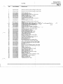
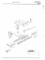
LOWER PLATE SUPPORT
VACUUM APPLICATOR
MOD. 724
TAB. 3
\'
I
\
37
38 39
I
"//l§'
~)if1
42
,rCk;43
j1
pOID
OF VIEW o
I
1
Dynachem
VACUUM APPLICATOR
MOD. 724
LOWER PLATE SUPPORT
TAB. 3
~,
./~
REF.
PART NUMBER
2
3
4
5
6
7
8
9
10
11
12
13
14
15
16
17
18
19
20
21
22
23
24
25
26
27
28
29
30
31
32
33
34
35
36
37
38
39
40
41
42
43
44
45
46
47
48
49
50
51
52
53
54
55
56
57
015-22-399-00
015-22-406-00
015-01-039-00
015-01-039-01
015-01-039-02
01 5-01-039-03
015-21-217-00
015-21-226-00
015-01-038-00
015-02-070-01
015-22-407-00
015-22-359-00
015-22-359-01
015-22-359-02
015-22-359-03
015-22-359-04
015-22-359-05
015-22-301-00
015-22-359-06
015-22-359-07
015-22-431-00
015-22-360-00
015-22-438-00
015-22-361-00
015-22-362-00
015-22-363-00
015-22-408-00
015-22-364-00
015-02-068-00
015-22-451-00
015-22-409-00
015-22-365-00
015-22-366-00
015-22-410-00
015-22-457-00
015-22-367-00
015-22-368-00
015-22-411-00
015-22-369-00
015-20-108-01
015-22-370-00
015-22-412-00
015-22-430-00
015-01-014-00
015-22-450-00
015-22-371-00
015-22-372-00
015-22-373-00
015-22-374-00
015-22-414-00
015-02-070-00
015-22-375-00
015-22-415-00
015-02-070-02
015-22-401-00
015-22-376-00
015-22-439-00
DESCRIZIONE
DESCRIPTION
SCREW TCEI M5 x 10
SPACING SUPPORT FOR SHOCK ABSORBER 15077
SHOCK ABSORBER 35 x 40 DPB
SPRING
HEAD FOR SHOCK ABSORBER 15099
HEAD FOR SHOCK ABSORBER 15062
ELBOW MIF 1/8 A 10
NIPPLE 1/8"-1/8"
AIR FLOW REGULATOR URG 8/2 .
ROLLER BEARING GUIDE-VACUl)M HOSE
SCREW TSTC M8 x 20
SUPPORT ASSEMBLY
BEARING ROLLON
SUPPORT 15080
SCREW TCEI M8 x 55
BUSHING
PIN
COLLAR BUSHING 12,1 x 16 x 18
LOWER HOSE BLOCKING 15154
UPPER HOSE BLOCKING 15155
SCREW TCEI M5 x 35
PLATE 15085
SCREW TCEI M8 x 20
COLLAR BUSHING 150681A
!
NUT FOR FIX. THE CYLINDER 151tlC
SPACING COLLAR 15052/8
I
SCREW TCEI M6 x 25
.
HEAD FOR CYLINDER 150341A
I
lXl3
GUIDE BRACKET ~ BOT PLATEN
SCREW TCEI Ml0 x 35
SCREW TSPC M4 x 15
READ. PLATE FOR PROXIMITY (LE T) 151131A
TROLLEY LOWER PLATE SUPPOR ING 15018/A
SCREW TCEI M12 x 30
I
WASHER d. 13-20
PIN FOR PLATE CENTERING 1515
DOWN STROKE CAM 150231A
SCREW TCEI M4 x 15
I
UP STROKE CAM 15087
~ PROXIMITY SWITCH 3RG-4013-0A 00 (12)18 mm) t
~~~~~~~E7~:~~ci 15088
i
READ. PLATE FOR PROXIMITY (RI~HT) 15112/A ORIGA CYLINDER 120 S20S 40 x 8 0 I
SCREW TCEI M6 x 20
I
STOP CYLINDER BRACKET 15078 I
i
TOWING BRACKET 15084
LEFT SPACING PLATE 15092
RIGHT SPACING PLATE 15067
SCREW TCEI M8 x 45
ROLLER BEARING GUIDE-LOWER PLATEN
ROLLER BEARING SUPPORT 1506f
SCREW TSTC MB , 30
LOCKING SCREW
NUT M8
SPACING SUPPORT FOR SHOCK
SCREW TCEI M5 x 20
t
BSORBER 15082
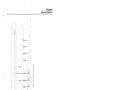
DynachemVACUUM SYSTEM
VACUUM APPLICATOR ~OD. 724 AB.4
Dynachem
VACUUM APPLICATOR
MOD. 724
VACUUM SYSTEM
TAB. 4
REF.
PART NUMBER
DESCRIPTION
VIBRATION FEET ABSORBER M1
Th;,k
SLIDE SUPPORT FOR PUMP
SPRING
PUMP BLOCKING BRACKET 0130.00.005
WASHER d. 8,4·17
SCREW TCEI M8 x 30
SET SCREW M6 x 25
34
35
36
37
38
39
40
41
42
43
44
45
46
47
48
49
50
015-22-303-00
015-22-377-00
015-22-378-00
015-22-379-00
015-22-394-00
015-22-416-00
015-22-417-00
015·22·391-(.10
015·22-418-00
015-22-419·00
015-22-405-00
015-22·380-00
015-22-381-00
015·22-382-00
015-22-383-00
015-22-420-00
015·00-00 1-00
015-21-201·00
015-01·055·00
015-22-438·00
015-21·227-00
015-22-422-00
015-21-228-00
015·01·047-01
.015·01·073-00
015-01·074·00
015-21-202-00
015-01-061·00
015-01-033-00
015·00-005-00
015-01-056-00
015-21-229-00
015-21-204-00
015-21-220-00
015-22·304·00
015-22-439-00
015-21-203·00
015-21-223-00
015-21-223-01
015-22-423-00
015·22·424-00
015-21-224-00
015-01-047-00
015-00 004-00
015·21-230-00
015·21-200·00
015-21-225-00
015-22·425·00
015-22·426-00
015-22-384-00
51
015-22·302·00
PVC BOX
1
2
3
4
5
6
7
8
9
10
11
12
13
14
15
16
17
18
19
20
21
22
23
24
25
26
27
28
29
30
31
32
33
---.,
1"'0
0130.~.001
NUTM6
WASHER d. 10,5-21
NUTM10
I
SCREW TSTC M6 x 20
1
SLIDING PLATE 0130.00.002
LEFT SLIDING GUIDE 0130.00.004,
RIGHT SLIDING GUIDE 0130.00.003
HANDLE DEVICE
SCREW TE M10 x 20
PUMP EDWARDS E2 M40
CENTERING SPACING COLLAR 10~.14.396
COUPLING FLANGE 110-04-440
SCREW TCEI M8 x 20
COUPLING FLANGE
SCREW TCEI M8 x 25
I
REDUCING UNION
QUICK ADAPTER CLAMPS 105-14-402
I'
I
~g~~ ~g~:~~~ ~~ ~~~~~ ~g~:~:j:
CENTERING SPACING COLLAR 105-11-396
VAC. HOSE CLAMP QUICK REL. C105-12-402
PIRANI GAUGE HEAD PRH 10K
ELECTROVALVEPVA10EK
I
ELBOW 105-14·410
I
HOSE CONNECTION 15026
I
HOSE CLAMPS SERF LEX 25-45
,
YELLOW VACUUM HOSE d. 28
MANIFOLD FOR MILSPEC CONNEFT. 15143
SCREW TCEI M5 x 20
'0' RING 3200
"
BACK HOSE BLOCKING 15123 DEf' ICE
FRONT HOSE BLOCKING 15122 D VICE
SCREW TCEI M4 x 3 0 "
SCREW TCEI M5 x 12
SPECIAL ELBOW 15101
I
QUICK ADAPTER CLAMPS 105-14-/1.01
ELECTROVALVEPV25EK
'
HOSE CONNECTION
TEE PIECE UNION 105·14-411
RUBBER SPACING
t'
SCREW TCEI M4 x 12
WASHER d. 4,3x9
ELECTROVALVE SUPPORT DEVI E 15103/3
'0
PEAlillAZIONF TIPQurOGRAfIA TlRILETT!, AZZATE
-7- \\ \\.
\
\
14
~~
'
--3
1
i
19je-20
--3
4-~ ~ i1-7
v /'
~
('/ 0-
e
~-14
18-
~
~~--'-U
tCJ[J~ if ~~__
,.)
-
--- ---
35
26
)
C1~:XJ
. ..... Cj
-li:!:
»0
(')
tD~»
~
3
:T
fb
('I
QJ
i:,<
~ CJ
» ::J
<
»
(')
~
m
i:
-<
»
$
en
Dynachem
AIR SYSTEM
VACUUM APPLICATOR
MOD. 724 TAB. 5 ~.
REF.
PART NUMBER
OESCR IPTION
2
3
4
5
6
7
6
9
10 11 015-21-211-00
015-21-216-00
015-21-214-00
015-21-212-00
015-21-207-01
015-22-450-00
015-21-219-00
015-21-206-00
015-22-440-00
015-00-040-01
015-00-040-00
TAPER CONNECTION 1/4" . 10/8 TEE PIECE UNION FIF 1/4" All TAPER CONNECTION 1/4" A2 ELBOW 1/4" 10/8 C5 MANIFOLD UDP 4S SCREW TCEI M6 x 20 BLUE HOSE 10/8 VALVE UDS 12 KUC/KUC SCREW TCEI M5 x 40 SCREW TCTC M3 x 30 CONNECTOR PLUG ELECTROVALVE ULR-l 12 13 14 15 16 17 18 19 20 21 22 23 24 25 26 27 28 29 30 31 32 33 34 35 015-00-008-01
015-22-442-00
015-01-003-00
015-21-213-00
015-01-015-00
015-21-215-00
015-21-231-00
015-21-205-00
015-21-221-00
015-21-232-00
015-22-431-00
015-21-233-00
015-21-226-00
015-00-040-02
015-21-222-00
015-01-031-05
015-22-390-00
015-22-389-00
015-21-208-00
015-21-208-01
015-01-031-02
015-01-031-01
015-01-031-03
015-01-031-04
SOLENOID 24V D.C.
i
SCREW TCEI M4 x 65
i
AIR FLOW REGULATOR URG 4/101
NIPPLE ADAPTER 112"-114"-A4 ! AIR PISTON COD. 1200, 200 x 50 ELBOW M/F 1/4 Al0 SPECIAL NIPPLE 15097 VALVE UKA 4132/U 1/4" SINGLE WAY VALVE U4 SPECIAL NIPPLE 15159 SCREW TCEI M5 x 35 MANIFOLD FOR PRESS. DETECT NIPPLE 1/8"-1/8" CONNECTOR PLUG FOR PRESSU E DETECTOR PRESSURE DETECTOR ES 2000 SUPPORT FOR LUBRICATOR SRW WASHER d. 6,4 x 12,5 SCREW TE M6 x 15 RAPID DISCHARGE VALVE 650.07. 13 AIR LOCKING NUT AIR FILTER UZR RM4 F20 1/4 REDUCER FRR 48 PRESSURE GAUGE M 012 LUBRICATOR L4 UZLAM 1/4 f'
1 68
1
t
~S
--. -
Dynachem
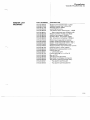
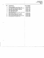
INSTRUMENT PANEL AND CONTROLS
VACUUM APPLICATOR
MOD. 724 TAB. 6 09
y __"
-8
Dynachem
VACUUM APPLICATOR
INSTRUMENT PANEL AND CONTRrLS
MOD. 724
TAB. 6
PART NUMBER
DESCRIPTION
015-20-096-00
RED PILOT LAMP "MAIN POWER
N" 080 LSRD
2
015-20-097 -00
GREEN PUSH-BUTTON "SET UP 0
"080 PLVG
3
015-20-094-00
4
015-20-101-00
BLACK PUSH-BUTTON "OFF VACU M PUMP"
080 PNG
THUMB WHEEL 3 DIGIT T56 ASSY
5
015-20-105-01
6
7
8
9
10
11
12
13
14
15
16
17
18
19
20
21
22
23
24
25
26
27
28
015-00-023-00
015-22-427-00
015-22-399-00
015-22-427-01
015-22-427-02
015-22-428-00
015-22-412-00
015-22-454-00
015-22-424-00
015-22-432-00
015-22-433-00
015-20-100-10
015-22-452-00
015-20-120-00
015-22-453-00
015-30-001-00
015-20-107-01
015-20-104-02
015-00-022-03
015-00-049-00
015-00-091-00
015-00-092-00
015-20-099-00
29
015-00-022-01
REF.
;
YELLOW SELECTOR SWITCH "PRE IMINARY
INSTRUCTION" 080 SMLDG
EMERGENCY STOP BUTTON ASSY
LOWER SUPPORT FOR MEASURES INSTR 15133
SCREW TCEI M5 x 10
KNOB M5 x20
PIN d_ 5 x 10
UPPER SUPPORT FOR MEASURE INSTR 15134
SCREW TCEI M4 x 20
LOWER BOX COVER 15142
~;~E~~C~~~:UXR~2INSTRUMENT~ 15140
REAR BOX COVER 15141
!
CONTROLLER MOD, 503 EDWARD$ SCREW TSTC M3 x 10
.
ALPHANUMERIC DISPLAY DAA 144 F3 ALUMINIUM ANODIZED PANEL TEMPERATURE REGULATOR E5CSjQ1KJX-522 RED PUSH-BUTTON "SET UP OFF' 080 PRG
LAMP HOLDER 080 ADV
CONTACTS (1NO+1NC) 080 B11V
INDICATOR LAMP 30V 2W
BLACK COMMANDS PANEL 0191.0 ,003
BLACK MESSAGES PANEL 0191,00004
ORANGE PUSH-BUTTON "ON VAC UM PUMP"
080 PLAG
YELLOW PUSH-BUTTON "CYCLE S ART"
080 PLGG
Dynachem
VACUUM APPLICATOR MOD. 724
SPARE PARTS ORDERS
ering parts, we suggest that the follow ing in
with the order:
To avoid errors when
formation be inclu
72.
FlO.
REF.
DESCRIPTION
Pressure detector
Thumbwheel2 dlgil T56 assy.
Magnetic switch safety transformer
TerminaL blOCk connection fuses holder
3 Phases rectifier SKD2Sf04
Solid etate relay 024-40
Magnetic switch 17V 3PH Safety line
Kindly supply the machine: Serial numbe
___._ Part number---,--_ Fig._......:....__ Q.ty--Ref.
Exact shipping addre
i
Shipping m e t h o d - _ - - - - - - - - - - - - - - - - -
Orders should be plaged with your local Dynachem office or distribu
tor.
i
IV-1
- - - - -..........
--~~-.~
..
--~
.....
------~
Dynachem
VACUUM APPLICATOR MOD. 724
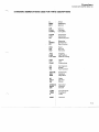
STANDARD ABBREVIATIONS USED FOR PARlIS DESCRIPTIONS A
Amps
ASSY
A33embly
BOT
Bottom
CIR
CYLN
COMPL
Circuit
Cylinder
Complete
CONN
CTR
CU'
Connector
Centering
Centering unit
D
DIMEN
EV
Diameter
Dimension
Electrovalve
FED
HR
IND
Feed
Hot roll
Indicator
JOG
LAM
LAT CUT
Jogging
Lamination
Lateral cutting
LEN
LFT
LUBE
Length
Left
Lubricating
OV
PH
PN
Old Version
Phase
Part Number
PNEUM.
REL
REG
Pneumatic
Release
Regulator
RT
SECT
SH
Right
Section
Shore
SPROCf
SUPP i
SW
Sprocket
Support
Switch
TEMP
TRNS
V
Temperature
Transport
Volts
VERT
Vertical
.~
---....,
IV·2
Dynachem
VACUUM APPLICATOR MOO. 724
MASTER LIST
ELECTRIC
PART NUMBER
015-20-111-00
015-20-114-01
015-20-114-00
015-20-111-00
015-20-112-00
015-20-113-01
015-20-117-00
015-20-118-00
015-20-119-00
015-00-041-00
015-00-028-00
015-20-121-00
015-20-122-00
015-20-101-00
01 5-00-041-01
015-00-041-02
015-20-117-01
015-20-117-02
015-20-106-00
015-20-106-01
015-20-106-02
015-20-106-03
015-20-098-01
015-20-106-05
01 5-20-120-01
015-20-098-00
015-20-1 03-00
015-20-116-00
015-20-115-00
015-20-110-00
015-30-001-00
015-00-058-01
015-00-058-02
015-20-120-00
015-20-108-01
015-20-109-00
015-20-013-00
015-20-095-00
015-20-102-02
ESCRIPTION
PH Magnetothermal switch (I = 40A) Siemens
SN3-340-1B
3PH Magnetothermal switch (I = 20-25A) Telemeca
nique GV1-M22
~PH Magnetothermal switch (I = 16-20A) Telemeca
mique GV1-M21
~PH Magnetothermal switch (I = 40A) Siemens
5SN3-340-1B
3PH Magnetothermal switch (I = 6A) Siemens
5SN3-306-1B
~PH Magnetothermal switch (I =6,3-1 OA) Siemens
~VE1-01 0-2L
Ifuse holder clamp Weidmuller SAK S1
$tatic relay Crydon 02440
lHeat dissipator for static relay 107x175 mm
Fuse holder Hager 4501
3PH Contactor Siemens 3TB42-17 OA N1
3PH Diode rectifier Semikron SKD 25/04
~eat dissipator for diode rectifier S40/75
4 digit preselector (assy) Cherry T56
Ifuse 10,3x38 mm (I=16A F.F.)
Ituse 10,3x38 mm (1=6,3A F.F.)
~use 5x20 mm (I = 1A F.)
Ifuse 5x20 mm (I = 0,8A M.)
WLC Saia (assy for Vacuumex 724)
Main board PLC Saia PCA1.M51-M4
1/0 board for PLC Saia PCA 1.B90
Output board for PLC Saia PCA1.A21
lDiode 1N4148
~rograms PLC Eprom Texas JL25 (2764)
Messages display Eprom SGS IFI (2716)
Oiode 1N4002
3PH Main switch Breter 3.03.11 - OP
3PH OK light indicator CGE-Cema 105 DTL 500
~PH Microswitch CGE-Cema 114-FCT03
ransformer 8,2 KVA 50/60 Hz
emperature regulator Omron E5CS-Q1 KJX-522
il spec connector Bendix MS3102-R18-10P (male)
il spec connector Bendix MS3106-R18-10S
( emale)
Iphanumeric display Mueller-Weigert OM 144-F3
roximity switch Siemens 3RG 4013-0ABOO (0 18)
roximity switch Siemens 3RG 4012-0ABOO (0 12)
icroswitch Omron Z15 GW22 digit preselector (assy) Cherry T56 nnector for preselector BCD '
f
IV-3
Dynachem
VACUUM APPLICATOR MOD. 724
PART NUMBER
PESCRIPTION 015-20-096-00
015-20-104-02
015-00-049-00
Aed pilot lamp "MAIN POWER ON" CGE-Cema
080 LSRD
Lamp holder CGE-Cema 080 ADV
Indicator lamp 30V - 2W
015-20-097-00
~reen
015-20-104-02
015-00-022-03
015-00-049-00
015-20-107-01
015-00-023-02
015-20-099-00
015-20-104-02
015-00-022-03
015-00-049-00
015-20-094-00
015-00-023-02
015-00-022-01
015-20-104-02
015-00-022-03
015-00-049-00
push button "SET UP ON" CGE-Cema 080
f!>LVG
" amp holder CGE-Cema 080 ADV
" ontacts (1 NO + 1NC) CGE-Cema 080 B11 V
I dicator lamp 30V - 2W
~"
ed push button "SET UP OFF" CGE-Cema 080
RG
ontacts (1 NO + 1 NC) CGE-Cema 080 BF11V
i
Orange push button "START PUMP" CGE-Cema 080 PLAG tamp holder CGE-Cema 080 ADV Contacts (1 NO + 1 NC) CGE-Cema 080 B11 V Indicator lamp 30V - 2W $Iack push button "STOP PUMP" CGE-Cema 080 f1>NG ¢ontacts (1 NO + 1NC) CGE-Cema 080 BF11 V Yellow push button "CYCLE" CGE-Cema 080 PLGG Lamp holder CGE-Cema 080 ADV ¢ontacts (1NO+1NC) CGE-Cema 080 B11V Ihdicator lamp 30V - 2W 015-20-104-02
015-00-022-03
015-00-049-00
tellow selec.tor switch "PRELIMINARY INSTRUC
TION" CGE-Cema 080 SMLDG 4amp holder CGE-Cema 080 ADV q;ontacts (1 NO + 11\1C) CGE-Cema 080 B11V Indicator lamp 30V - 2W 015-00-023-01
015-00-023-04
El=mergency push button CGE-Cema 077 EER Contact (1 NO) CGE-Cema 077 E01 015-00-091-00
015-00-092-00
015-00-093-00
015-00-093-01
015-00-093-02
015-00-093-03
015-00-093-04
015-00-093-05
015-20-120-02
015-20-120-03
015-00-023-03
015-00-094-00
Black commands panel 0191.00.003 Black messages panel 0191.00.004 Muffin fan connector (assy) Muffin fan connector (free) ty1uffin fan connector (whole) tjt1uffin fan connector (female) ty1uffin fan connector (male) Muffin fan connector (cable holder) Resistor 22 K a 1/2 W ~esistor 1.5 K a 1/2 W ¢ellow aluminium disk 0158.00.082 I anneetar 10 poles ILME CNE 10 IVO
015-20-105-01
IV-4
I
-
Dynachem
VACUUM APPLICATOR MOD. 724
MASTER LIST
PNEUMATIC PART NUMBER
DESCRIPTION
015-01-003-00
015-01-014-00
015-01-015-00
015-01-031-00
015-01-031-01
Air flow regulator URG 4/10
ir cylinder Origa-40 x 800
ircylinder Fineco-1200
ir filter regulator assy.
. Reducer FRR48
i
015-01-031-02
015-01-031-03
015-01-031-04
015-01-031-05
015-01-033-00
015-01-038-00
015-01-039-00
015-01-047-00
015-01-047-01
015-01-055-00
015-01-056-00
015-01-057-00
015-01-073-00
015-01-074-00
015-21-200-00
015-21-201-00
015-21-202-00
015-21-203-00
015-21-204-00
015-21-205-00
015-21-206-00
015-21-207-00
015-21-208-00
015-21-209-00
015-21-210-00
f
Filter
Pressure gauge M012
Lubricator L4
'i Support for lubricating sys, SRW4
irani gauge PRM10K
I
I
l
ir flow regoulator URG8/2 ir cylinder 35 x 40 DP . uick adapter clamps 105-14-401
'. Quickadapterclamps105-114-402
<J;oupling flange 110-04·440
~
lbOW
105-14-410 -ring type 3100 ose adapter KF40/25105-16-439 ose adapter KF25/10 105-14-436 .ee piece union 105-14-411
Centering spacing collar 105-14-396
Centering spacing collar 105-11-396
O-ring type 3200
ose clamps Serflex 25-45 alve UKA 4/32/U 1/4" ~
alve U DS 12 KUC/KUC
anifold
Rapid discharge valve
Male nipple 1/4" -10/8" L-C5
Air quick disconnect 615
015-21-211-00
015-21-212-00
015-21-213-00
015·21-214-00
015-21-215-00
~
015-21-216-00
015-21·217 -00
015-21·218-00
015-21-219-00
015·21-220-00
l1ee piece union F/F 1/4A11
Elbow M/F 1/8A10
aper connection 118 A2
lue hose 10/8
ellow vacuum hose
015·21-221-00
015-21-222-00
aper connection 1/4" -10/8" C1 Ibow 1/4" - 10/8" C5 ipple adapter 1/2 - 1/4 A4 aper connection 1/4 A2 Elbow M/F 1/4 A 10
~
ingle way valve U4
Pressure detector
IV-5
Dynachem
VACUUM APPLICATOR MOD. 724
MASTER LIST
MECHANIC
PART NUMBER
I
ESCRIPTION
015-02-009-00
015-02-010-00
015-02-011-00
015-02-054-00
015-02-060-00
ubber shim blanket bot 1.6 mm
Rubber blanket top 1.6 mm OV
$ealing gasket 15057
Leveling feet assy.
Top platen secur block assy. - 15005
015-02-060-01
015-02-062-00
015-02-063-00
015-02-068-00
015-02-069-00
.• Securing block bolt CEM12 x 60
Rubber blanket frame top 15032
nchor for platens 15046/A
uide braket - bot platen 15033
xt. Air piston, bot platen 15034/A
015-02-070-00
015-02-076-00
015-02-077 -00
015-02-078-00
015-02-079-00
015-02-081-00
015-02-082-00
015-22-300-00
015-22-300-01
015-22-301-00
015-22-302-00
015-22-303-00
015-22-304-00
015-22-305-00
015-22-305-01
015-22-305-02
oller bearing guide bot platen
eater retaining plate 8 mm (.315")
eater retai ning plate 3 mm (.118")
ubber shim blanket bot 4 mm
ubber blanket top reinforced 1.6 mm
aiding guard - lower platen
ubber shim blanket bot 3 mm
oking key RT
. Loki ng key LFT
oller bushing 12,1 x 16 x 18
ox in PVC
ibration feet absorber
anifold for milspec connector
op platen opening holder assy.
Top platen opening pin
Top platen opening braket
[Y·6
- - - - - - - - - - - - - - - - _ ..................
_
Dynachem
VACUUM APPLICATOR
MOD. 724
FIG. 1
ISSlI ED 1.1086 REV.
1
Dynachem
VACUUM APPLICATOR
MOD. 724
FIG. 1
-
~
REF.
DESCRIPTION
PART NUMBER
1
2
3
4
5
Valve UKA 4/32/U 1/4"
Reducer FRR48
Pressure gauge M012
Lubricator L4
Filter
015-21-205-00
015-01-031-01
015-01-031-03
015-01-031-04
015-01-031-02
6
Rapid discharge valve
015·21·208·00
Manifold
Valve UDS 12 KUC/KUC
Air flow regulator URG8/2
015-21-207-00
015-21-206-00
015-01-038-00
Air cylinder Fineco-1200
Air cylinder Origa-4O x SOO
Roller bearing guide bolt platen
Ext. air piston, bot platen 15034/A
Guide braket - bot platen 15033
Air cylinder 35 x 40 DP
Proximity switch Siemens 3RG 4013-0ABOO (01
015-01-015-00
015-01-014-00
015-02-070-00
015-02-069-00
015-02-068-00
015-01-039-00
015-20-1 08-01
7
8
9
10
11
12
13
14
15
16
17
18
Dynachem
VACUUM APPLICATOR
MOD. 724
FIG. 2
NOTE
ISSUED 1.1086
REV.
1
Dynachem
VACUUM APPLICATOR
MOD. 724
FIG. 2
----..... --,
REF.
1
2
3
4
5
DESCRIPTION
Pirani gauge PRM10K
--"Eiecfrovalve"WiOEK
Electrovalve PV 25EK
Pump Edwards E2M40
Box in PVC
PART NUMBER
015-01-033-00 015-00-005-00 015-00-004-00 015-00-001-00 015-22-302-00 i
I
i
1
Dynachem
VACUUM APPLICATOR
MOO. 724
FIG. 3
NOTE
ISSUED 1.1086
REV.
--:-;>.
. -~-
- "
1
Dynachem
VACUUM APPLICATOR
MOD. 724
FIG. 3
REF.
1
2
3
4
5
6
7
8
9
10
11
DESCRIPTION
JART NUMBER
Mil spec connector 3102/18-10P
. Quick adapter clamps 105-21-043
Manifold for milspec connector
Elbow 105-14-410
Top platen opening holder assy.
015-00-058-00
015-01-047-01
015-22-304-00
015-01-056-00
015-22-305-00
Rubber blanket top 1.6 mm OV
015-02·009·00
Top platen opening holder assy.
Yellow vacuum hose
•
. Securing block bolt CEM 12 x 60
Top platen secur block assy. - 1500
I
Proximity switch Siemens 3RG 4012-0ABOO (012~
015-22-305-00
015-21-220-00
015-02-060-01
015-02-060-00
015-20-109-00
Dynachem
VACUUM APPLICATOR
MOD. 724
FIG. 4
NOTE
ISSUED 1.1086
REV.
1
Dynachem
VACUUM APPLICATOR
MOD. 724
FIG. 4
REF.
DESCRIPTION
PART NUMBER
Pressure detector
Two digit preselector (assy) Cherry T56
3PH magnetothermal switch safety transformer
Fuse holder clamp Weidmuller SAK S1
3PH diode rectifier Semikron SKD 25/04
015-21-222-00
015-20-101-00
015-20-114-00
015-20-117-00
015-20-121-00
6
Static relay Crydom 02440
015·20·118·00
7
8
9
3PH magnetothermal switch
Fuse holder Hager L501
3PH magnetothermal switch safety motor pump
Siemens 3VE1-010-2L
3PH contactor Siemens 3TB42-170A-N1
3PH microswitch CGE-Cema 114-FCT03
3PH main switch Breter 3.03.11-0P
3PH ok light indicator CGE-Cema 105DTL500
PLC Saia (assy for vacuumex 724)
015-20-112-00
015-00-041-00
1
2
3
4
5
10
11
12
13
14
015-20-113-01
015-00-028-00
015-20-115-00
015-20-1 03-00
015-20-11 6-00
015-20-106-00
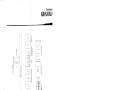
)1
4.6
Rl OE
Ev
Ev
Fc
--=
$K
+
Page where command is positioned
p~'ion" 0. .",.,
Electrovalve
Electrovalve
?
Switch
Pilot lamp
Block connection
fuse holder
Fuse holder
Condenser
Contact
N.O. + N.C.
Contact N.C.
Contact N.O.
Coil of relay
Rectifier +
cooling system
0+ S
Proximity switch cap. L
Col"mn who,. ,omm.n' I,
$
f
$
F
CA
7
+
(
~
$
WE
Microswitch N.C.
Microswitch N.O.
Push button N.C.
Push button N.O.
R
Pm,'mltyow'tch In";;-l-
T
11
T
ir
E-<
T
T
ire
t
Male· female
connector
Block connection
FC~
Fe
Fc
S
s
CN
?
)
Potentiometre
LJJ
___ .1 K~'
~
I®®®I
a_~
,
,
L
RL-mIID-
AZ~
=>
Z
Z
T
11
T
11
-$
T
.r-
T'W
J
Automatic switch OFF
Solid state relay +
cooling system
l=
,- ----,.*
CN:@@@l
L _____ -'
Fc
elem~nt--~Rc
3PH OK light
indicator
Heat
Driver
BCD commutator
Gear motor +
field coil
Diode
3PH rectifier +
cooling system
$~z
-[>t-
~=*t
c~
RV
0
0
Contact N.C.
Contact N.O.
Coil of remote
control switch
filter
~ARC voltage .
Inductance
Reactance
Temperature
regulator
Thermocouple
Contact brush +
connector ring
Air pressure
gauge
<
~~
~
i~ o~
~
r-
"tI "tI »
c:
c:
3:
0
"J>
)
,,)
r
~
Air exhaust
ventilator
LD@)-
~
N.O. contact
Timer
Push button lamp
Buzzer alarm
Flashing alarm
--N.C:contact
$..nJ1...
S.
SA
so
~-
~T
Tep
o
00
Led
"
!
!
I
II
.,,--;:::; ~-, , , I
EN
R
Of
.¥
-I_I
$-----$
Photocell
Reed microswitch
Block connection
+ led indication
Encoder
Buffer relays
module
Antistatic bars
~ T~"'fom"
T
FC~
FC
A-=-t::3- 24Vc.c. Power supply ML
®
Motor+dynamo
<
~~ g~
~g.
£~ "lJ "lJ iii:
l>
c::
c::
(')
"»
)
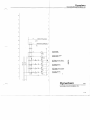
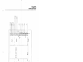
Dynachem
VACUUM APPLICATOR MOD. 724
~
Control box
muffin fan
'"
;:!
Motor pump
mullin fan
~
r
u
N
~
Vacuum pump
(220V)
;::
._.1
91
...,
u>
" '" ""
(""I,
M
M
0
---I
0>
<J
I
m
r<
N
.Ii
;;:;
C!
_________ J
""
>
>
'"
t-
~
...
~
-
c-
N
o
'"
-
~
...>
t-
N
Main transformer
Ii
N
-'
'"-'
&
,
,
I
Ii
I
• !
0
-'
0 '3
M
-'
-II
bHl "
~t
I
._",,"'---,
3PH OK light indicator
Main power switch
0
b::
Dynachem
1111
VACUUM APPLICATOR MOD. 724
V·1
<
r\.)
;:
~
~
-.j
...,
p
3:
0
::D
0
-f
r
(;
"'0
"'0
~
......
,. ~ n
,. i
3
c:
c:
3:
0
)
t
VACUU"
METEIt
~1 --7.11
19
K2~
l
VM1:
<
i
3
3
!§"
.
81
Tel
7.\1
-i
..,cOJ
~
OJ .~
i
<it
3
.g
b
CN1--------
:a
li '3 ::r IRa
.. ~ ~~
I+~
F3
FF
B
Tc2
CN2
~Ii I~ I-~
t+ r-
I
0;3
~i!
1
3~
g!
'iii'"
220
220 V 'I>
6
__
4.7 ~ 181
5
v'\, 6
220
220 V'I>
5
"
220 V '\,
nov,"
4
)
,.
<
3
~i
~~ £~ r
"'0
"'0
,.
c:
c:
3:
0
I~
)
--
~
M
----~- - ~~~--'----=---
<
~
~....
~
£
......
Ie!
3
I~ ~
Ii
r
"D
»
"D
3:
c::
c:
Alphanumeric display block- connection
-----
---.!>---------0-----+-------'>-----+-5.2
30
"~,__
5
(l)
29
eNS!
(2)
7B _____~----~,-----~----~~----+_----------~------~----~----~------------~
(1)
220
no V'b
if,
7A
5
)
1;
ANt
220V'b
4
)
~C ':j
~ ~ =' ~~ ~)
-,
<
t..J
II.)
......
..
!=I
0
I~
(1)
9
~
g
3
s:
~
~~
:~
)
\
6
4
(1)
7A
28
1
1\
98
(32)
It
lOA
(64)
J\
5A
a:]
-t~
*'Re3
6.6
)Il
Re5
22K
67
*'
6.8
.
6.9
Alphanumeric display block connection
~513
I
50
1
20A
.. --- -t ----L-- ---t;---- -t~,- -- t~--- ---------1~6 ----1
J\
9,0.
as
SA
1\
(16)
(8)
(4)
-1
~if
k
t !
Re6
Re7
22K
22K
22K
'---~~-___<o___-___<_ ____<_ ___"'--__4_-5.2
29
(2)
78
- I
'----~,
AN1
nov,"
- -
1\
20B
1.9
t';-- T
1\
+
lA-B
~~l
4 10
_
__6_
5
F"
4
1':'
nov,"
~~~ ___2lQ.V.'!:
9
_ _ _ _ _-'2=20~\I 'b
e
nov'b
6.
220 V 'b
4.
I~ ~
:~
0:r
~"<
~O
"0
"0
l>
s:
c:
c:
0
.,.<
)
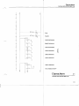
Dynachem
VACUUM APPLICATOR MOD. 724
0
Alphanumeric ground
""
"'''
u-i~
oM
=>
~
;:;:;
AIE!hanumeric sliding list
,.,
~
Os
A
'"
co
'"=>
'N"
"
0:>
<-
'S
A
Vacuum pump remole
control switch
"
"
A-
U'
N "
=>
° <-
'"
0
N
N
N
N
0
<.f'
>
0'>
(J)
u..
'"
A
<f'
>
0
N
N
...
~
.~
"...
«)
u..
.=>
"'-'..;;,?
..f?-.I
o~"
ON::>
-..1"'1
:;
0'>
M
t-
u..
<D
u..
,
¥.
0
-I
J
N.C. Upper vacuum release
electrovalve
c..
'S
.e:J
0
N.C. upper vacuum
electrovalve
'""
N.O. lower vacuum release
electrovalve
...
N.C. lower vacuum
electrovalve
0
(.)
..J
---j
~
LD
Dynachem
4/11
VACUUM APPLICATOR MOD. 724
V-4
&.
<:
,....,
~
.....
P
~o
....
Ii!!
....
3
E~
;2
~ ("\
~
g~
;;:
)
"'3
i""
!!.
<il"
"'<
N
"
3
or
n
::r
-'"
ia
....
"2.
[
::I
;=
-<
~.
c:
,..
C~D'G)
~a'
3::1
"
"'0
n
a;
gil)
i~
'"":x:
50
c:
"
h
Z
I"
PLC
~
8
)
"
o
S5L
"
3
a;
8.4
c
~
1:
3
~
I~
50H
L._ L8.l2
S
~
....75
U1:
.~
Ul0
51(+
16
~3
~~
0:r
P(I)
E~
""r-
»
:!:
c:
c:
~
o
)
Dynachem
V,ACUUM APPLICATOR MOD. 724
Pump ON
+
cr,
0;
::>
M
Weight 64 alphanumeric
~
"
aN
M
::>
Weight 32 alphanumeric
co
M
M
(j)
5
..
:~
Weight 16 alphanumeric
~
a:>
N
M
"
::>
I">
\!l
M
:;
'"
U
..J
Q.
Weight 8 alphanumeric
~
a
~
:;
o
Weight 4 alphanumeric
'"""
Weight 2 alphanumeric
::>
"
M
~----,.+
Weight 1 alphanumeric
M
'3
Out per multiplex «slap down»
I
(5
U1
Dynachem
6111
VACUUM APPLICATOR MOD. 724
V-6
Dynachem
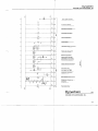
VACUUM APPLICATOR MOD. 724
.!il
G')
~r--------+-~---;
Start signal from MHU
~'
Air pressure detector.
'-
~-----------------co----------------~~o-·
v
u..
Sale guard microswitch
Stop pump push button
N
co
pump on push button
Vacuum alarm
Top platen closed microswitch
Platen down microswitch
"
I
r.=======;:..=====:t.."'~i
. f:i
Platen up microswitch
."
r-1A--r-"""\~
Signal to MHU that the lower plate is not moving Platen forward microswitch
(.)
...J
a.
U')
Platen backward microswltch
H
;;
a.
E
Push button start
u
oJ
r-------------.-------r-------r~~I~
Start signal from MHU
Preliminary instructions
Motor thermal remote control
Emergency common line
Emergency
a
<'
Push bullon set·up
Dynachem
7/11
VACUUM APPLICATOR MOD. 724
Y-7
Dynachem
VACUUM APPLICATOR MOD. 724 ~
~j
<D
co
co
'"
t-
<0
0
""co
&5
'" en fri1:0
'"
"' '
ra
0
'J
-N;
•
Njl>t
~
co
!-'£p.>
!"::!
'"
:ti
.
{:;>t
"H:*
:::::
"-
N
U
~
~ -r-tr
£1
I
I
N
0'>
Gi
" -C
'"
r-
-l:::
N
~
u;2
..
0
'"
-C
L:~
;;:
III
r;:;::- ,..,
d)
N
0
c:
fiJ
~
u
0
•
-
co
..
e
:;;:
g:
t
....
d)
v
~
'"
~o~
'"
:;:;
Tu
..
v
.
i>J
~
I '"co
...
E
~
"-
t
:;::
0
'"
Dynachem
8/11
VACUUM APPLICATOR MOD. 724 V·8
Dynachem
VACUUM APPLICATOR MOD. 724
~
fi '"
l/
"r\>l
I
,,~
~LbJ
-IV
--=
r;;- ....
"• -
v
... '"v
....
tsru $2
:d
~r-D
.~
Y::-i
u
!
:c
"'
«I
'" ,....
OJ
NO
0
<D
c<>
en'"
CJ')
0>
m
OJ
a;
Dynachem
9111
VACUUM APPLICATOR MOD. 724
V-9
--)
"
6
')
7
~) 9
~ 2
6
"3
~
7
4
6
!--I
2~---------------T1
o
4
6
9
+
0
4
6
0
III
+
8
"10
12
'3
'4
15
•
9
10
11
12
13
III
J
Input
890
890
I~L I
L3
(".3
--
Input
_()utput
IPLcl
PCA130 )
Relays
III
2'
20
19
18
17
16
23
22
21
19
20
'"
i
Lf---l=~~~+-_-=-
890
peA 1 A21 RE.Lt:'
Output
Input
17
,.
16
"3
)
~3
=~
~?6
!i'-<
~O
,.!I:
~
c
c
....
.... ....
....
~
~ i:J
~? )
A 130
380V 1= 20'- 25A
415V h20:25A
1.80V I 15-:-20A
• 220V 1=1.0A
S
hi
n
3
, ,.
•
&
1
1
'9
28 27 ••
25
:: I
21
'"1
.0
11
I:
i
17
'0
12
13 ..•• •..•
PLC Block connection
111
rlo1
Fuse holder
block connection Block connectio- n
3PH rectifl er
Main breaker
Thermal overload
remote control
Solid stale relays
G
Fuses 'i~/Sl ( c) \)
I.. ~ _I 3PH OK microswitch
'--IF c1
Magnethermal switches
A~~l=o,8A~
C3
3PH OK light
I 01I
0 ,
oI
n
I
)
Contactors
)
:a;:
c:::-::)
Q.l
==~
=-:::I
c::::::::>
~~:::J
--.::::J
~
=-==
Eiii!!!it!:
c:::::
c:::::
I\l
.;::
.....
<
....
!='
.....
N
0
3:
:0
0
»
-t
»
3:
~
3
i
~
"r" n
()
c:
c:
~
)
*Make shunt between 6·7
wires connection when
Vacuumex is not connected.
""
---I
=
N° 5
Ground
N° 16
Free
Male plug on Vacuumex nO 2
Male plug on Vacuumex nO 1
Lower side block connection
Upper side block connection
Push button side
ITrJ fJJ;l 30
01,
POS.l
POS. 2
POS.3
POS.4 =
Plug for motor pump muffin fan
02
01
)
Display side
Fuses holder block connection
)
~
E~ ~~ 0:::r
~~
""
»
3:
c:
c:
<