1
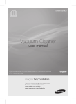
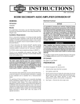
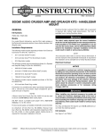
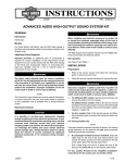
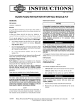
-J05699
REV. 2013-06-24
ADVANCED AUDIO CB RADIO KIT
GENERAL
ALL models will require the additional purchase of:
Kit Number
•
Non-Ultra Overlay Harness (70169-06A), and EITHER:
76000390
•
Premium Stereo Helmet Headset (77117-10) OR a HandHeld CB Microphone Kit (76312-98).
Models
All of these items are available from a Harley-Davidson Dealer.
For model fitment information, see the P&A Retail Catalog or
the Parts and Accessories section of www.harley-davidson.com
(English only).
Additional Parts Required
2006 models: Communication switch (77173-06)
2007 models: Communication switch (77173-07)
2008-later models: Communication switch (77173-08)
FLHT models will require prior installation of:
•
Advanced Audio AM/ FM/ CD Radio Kit (76412-06)
•
AM/ FM Antenna Kit (76325-06 or 76317-06)
Unless one has already been fitted as part of another Advanced
Audio kit installation:
2006-2007 FLHX models will require the separate purchase
of:
•
Fuel tank console (61270-98A)
•
Tank console gasket (71294-89C)
•
Button-head screw (3652)
•
Nut (7964)
•
Clip (10103 and 10120)
•
Tank pod mounting screws (2462) quantity 3
•
FLHT trim piece (52447-96) and CB pod trim badge
2008-later FLHX models:
•
Fuel tank console (61270-08)
•
Clips (10103 and 10120)
NOTE
The console screws, fuel door, gasket, mounting bracket will
all need to be reused.
FLTR models will require the separate purchase of:
•
Console Pod Assembly (77136-03), and
•
Pan head screws (2462) quantity 3.
If two modules are already installed on top of the radio, two
Dual-LockTM mounts (76434-06) will be needed.
Models WITHOUT a Tour-Pak installed will require additional
purchase of a Frame Mount CB Antenna Kit. 2006 through
2008 models: 76415-06. 2009 and later models: 76410-09.
Models WITH a Tour-Pak installed will require additional
purchase of a Tour-Pak Mount CB Antenna Kit. 2006 through
2008 models: 76414-06. 2009 and later models: 76400-09.
All of these items are available from a Harley-Davidson Dealer.
The rider's safety depends upon the correct installation
of this kit. Use the appropriate service manual procedures.
If the procedure is not within your capabilities or you do
not have the correct tools, have a Harley-Davidson dealer
perform the installation. Improper installation of this kit
could result in death or serious injury. (00333a)
NOTE
This instruction sheet references service manual information.
A service manual for your model motorcycle is required for this
installation and is available from a Harley-Davidson Dealer.
Electrical Overload
It is possible to overload your vehicle's charging system
by adding too many electrical accessories. If the combined
electrical accessories operating at any one time consume
more electrical current than the vehicle's charging system
can produce, the electrical consumption can discharge
the battery and cause damage to the vehicle's electrical
system. See an authorized Harley-Davidson dealer for
advice about the amount of current consumed by additional electrical accessories or for necessary wiring
changes. (00211c)
NOTE
See a Harley-Davidson dealer for availability of optional decorative inserts for the Console Pod Assembly.
-J05699
Many Harley-Davidson® Parts & Accessories are made of plastics and metals which can be recycled.
Please dispose of materials responsibly.
1 of 5
3.
When installing any electrical accessory, be certain not
to exceed the maximum amperage rating of the fuse or
circuit breaker protecting the affected circuit being modified. Exceeding the maximum amperage can lead to electrical failures, which could result in death or serious injury.
(00310a)
The CB Radio requires up to 2.0 Amps additional current from
the electrical system.
See Figure 1. Locate the CB radio module (1) on top of
the AM-FM radio case:
a.
Remove the screw (2) at the back of the radio.
b.
Position the CB radio module on top of the AM-FM
radio, with the metal cones on one end of the module
fitting firmly into the rightmost rubber grommets (3)
at the front of the radio.
c.
Fasten the module to the radio with the radio case
screw (2). Tighten to 35-45 in-lbs (4.0-5.1 Nm).
NOTE
If not already installed, the Fairing Speaker Switch and LeftHand Control Switch Assembly (purchased separately, individually or as part of the Communication Switch Kit) must be
installed at this time according to the instructions that follow.
Kit Contents
See Figure 3 and Table 1.
INSTALLATION
is00392
4.
1
2
On the fairing cap, remove the inner left side hole plug.
See the FAIRING CAP SWITCHES (FLHTC/U) section in
the service manual. Install the fairing speaker switch in
the opening as follows:
If a cruise control switch IS present:See FAIRING CAP
SWITCHES (FLHTC/U) in the service manual. Install the
Fairing Speaker Switch (purchased separately or as part
of the Communication Switch Kit) in the opening and
connect the wiring already there.
If a cruise control switch IS NOT present:
3
1. CB radio module
2. Radio case screw
3. Grommet (2)
1.
Refer to the service manual and follow the instructions
given to remove the main fuse.
2.
Remove the outer fairing and windshield. Refer to OUTER
FAIRING/ WINDSHIELD REMOVAL in the service manual.
Obtain the speaker switch adapter wire (purchased
separately or as part of the Communication Switch
Kit) and the butt splice connector included with the
speaker switch.
b.
Refer to SEALED SPLICE CONNECTORS in the
service manual. Splice the adapter wire to the black/
green speaker switch lead.
c.
Insert the terminated end of the adapter wire into
cavity 12 of the fairing cap switch connector [105B].
5.
Remove the original equipment left-hand control switch
assembly per the HANDLEBAR SWITCHES, REMOVAL,
LEFT HANDLEBAR CONTROLS instructions in the service
manual.
6.
Install the new left-hand control switch assembly (purchased separately or as part of the Communication Switch
Kit).
Figure 1. CB Radio Module Installation
To prevent accidental vehicle start-up, which could cause
death or serious injury, remove main fuse before proceeding. (00251b)
a.
When servicing the fuel system, do not smoke or allow
open flame or sparks in the vicinity. Gasoline is extremely
flammable and highly explosive, which could result in
death or serious injury. (00330a)
NOTE
If another module has been installed in the location reserved
for the CB radio module, relocate that module per the instructions supplied with that kit.
-J05699
2 of 5
7.
ALL models: Install the Console Pod Assembly.
a.
Note the routing of the main harness, fuel level
sender/ fuel pump conduit, and fuel vapor vent tube
as they travel beneath the console.
b.
Carefully cut the anchored cable strap securing the
main harness, fuel level sender/ fuel pump conduit,
and fuel vapor vent tube to the left side of the frame
backbone.
c.
Open the fuel door on the console. Remove the two
Allen head screws inboard of the rubber bumpers.
These screws secure the console to the clip nuts on
the canopy bracket.
All models EXCEPT FLHX: Remove the Allen head
screw to detach the flange at the rear of the console
from the clip nut on the fuel tank weldment.
NOTES
2006 and 2007 models require new rubber molding and 2008
and later models reuse rubber molding.
Make sure the rubber molding (new rubber molding 71294-89
for FLHX models) on the bottom of the console is seated
properly along its entire length.
FLHX models: Mount the adhesive-backed metal wire clip
(10103) to the underside of the console to hold the pod harness
and CB antenna.
Mount the plastic wire clip (10120) to the underside of the
console to hold the fuel vapor vent tube.
9.
Install the console to the tank.
a.
FLHX models: Remove the bolt (with flat washer) at
the rear of the fuel tank to release the console
bracket. This also frees the rear of the tank from the
frame backbone.
Route the pod harness and the CB antenna cable
forward along the left side of the fuel tank canopy,
and out under the left front edge of the console. Be
sure that the hoses and wires are not pinched by the
console during installation. Install the filler cap.
Remove the two screws that fasten the fuel door to
the console, and remove the door. Remove the hinge
mounting clip, and the hinge pin. Save these parts
for installation.
d.
b.
Lay a clean shop towel on the forward part of the rear
fender. Remove the filler cap from the neck of the fuel
tank.
All models EXCEPT FLHX: Install the Allen head
screw removed earlier to fasten the rear flange of the
console to the clip nut on the fuel tank weldment.
FLHX models: Install the 1/4-20 clip nut (7964) onto
the bracket on the fuel tank. Install the console
extension (52446-96) onto the rear of the console
with the button-head screw (3652) and clip nut.
All models EXCEPT FLHX: Remove the console
and lay it upside down on the shop towel. Install the
filler cap.
ALL models: Tighten the screw to 25-30 in-lbs (2.83.4 Nm).
FLHX models: Remove the console and discard it.
Install the filler cap.
Obtain the new fuel tank console, 2006-2007 models
use (61270-98A) and 2008 and later models use
(61270-08). Install the fuel door to the new console,
and tighten securely.
c.
Open the fuel door on the console. Install the two
Allen head screws to secure the front of the console
to the clip nuts on the canopy bracket. Alternately
tighten the screws to 25-30 in-lbs (2.8-3.4 Nm).
d.
Snap the anchor of a new cable strap (10006, from
the CB Antenna Kit) into the hole on the left side of
the frame backbone.
Lay the console upside down on the shop towel.
Install the bolt (with flat washer) to secure the rear of
the fuel tank to the frame backbone. Tighten the bolt
to 15-20 ft-lbs (20-27 Nm).
e.
Remove the filler cap. Place the console over the filler
neck onto the canopy. Route the cables from beneath
the console in the same way as installed originally.
Tighten the cable strap capturing the main harness,
CB antenna cable, fuel level sender/ fuel pump conduit, and fuel vapor vent tube. Cut any excess cable
strap material.
Feed the pin housing and console pod conduit through
the top of the console, seating the Console Pod
Assembly in the recess. 2006 and 2007 models use
pod (77136-03) and 2008 and later models use pod
(77136-08). Pods come in communication switch kits.
Install three Phillips screws (2462) from the underside
to secure the pod to the console. Alternately tighten
the screws to 6-11 in-lbs (0.7-1.2 Nm).
e.
Route the harness and antenna cable down tight to
the fuel tank and use cable straps to fasten to the
main harness, as close to the fuel tank as possible.
f.
Continue the harness and cable forward into the
fairing, using cable straps to fasten to the main harness.
Route the pod harness toward the front of the console.
8.
Install the CB Antenna Mounting Kit per the instructions
in that kit.
Do not kink or pinch the fuel overflow line when installing
console. A blocked line can cause an overfilled tank to
leak. Gasoline is extremely flammable and highly
explosive, which could result in death or serious injury.
(00264a)
-J05699
Be sure that steering is smooth and free without interference. Interference with steering could result in loss of
vehicle control and death or serious injury. (00371a)
•
Be sure the wires or antenna cable do not pull tight
when handlebars are turned fully to left or right fork
stops.
10. Obtain the overlay harness (purchased separately), unless
already installed.
3 of 5
11. See Figure 2.
a.
Plug the overlay harness 12-place pin housing (1)
labeled "Intercom" [53] into the socket housing coming
from the console pod.
b.
See Figure 3. Connect the CB module (2) to the CB
module harness (1) as shown.
c.
See Figure 2. Connect the CB module harness connector from kit into connector [184] labeled "CB" (2)
on the Non-Ultra Overlay harness.
d.
Plug the 35-place radio socket housing [28] (3) into
the radio.
e.
Locate the interconnect harness audio connector [6B]
near the back of the radio. Plug 6-way pin housing
[6A] (4) on the overlay harness into socket housing
[6B].
f.
Plug the antenna cable connector into the mating
connector on the back of the CB radio module.
g.
Tighten the knurled nut on the antenna cable connector to secure the connector to the module.
12. Use cable straps (purchased separately) to fasten the
overlay harness and antenna wire to the existing harnesses inside the fairing.
13. Refer to the service manual and follow the instructions
given to install the main fuse.
14. Test the CB radio and the rest of the sound system for
proper operation. If poor CB reception or transmission is
noted, see SWR ADJUSTMENT, below.
15. Install the outer fairing and windshield. Refer to OUTER
FAIRING/ WINDSHIELD INSTALLATION in the service
manual.
SWR ADJUSTMENT
Standing wave ratio (SWR) is a technical term for the procedure
that checks how well the CB transmitter and antenna are
matched. If poor CB reception or transmission is noticed, the
SWR should be checked.
Adjusting the SWR is described in detail in the Harley-Davidson
FLT Electrical Diagnostic Manual; however, the SWR of the
frame-mounted CB antenna is adjusted by moving the two
rings on the loading coil up or down, rather than moving the
antenna up or down, or shortening the antenna by grinding.
To check SWR, an SWR meter or bridge is required. A HarleyDavidson dealer will either have an SWR meter and the
appropriate adapters, or can direct you to a CB repair shop for
an SWR check.
Since the operating procedures for SWR meters vary, be sure
the operating instructions for the SWR meter being used are
carefully followed.
is00393
3
4
1
2
1.
2.
3.
4.
12-place pin housing [53], labelled "Intercom" to console pod
12-place socket housing [184], labelled "CB" to CB radio module
35-place socket housing [28] to AM/ FM radio
6-place pin housing [6A], labelled "Interconnect"
Figure 2. Non-Ultra Overlay Harness
-J05699
4 of 5
SERVICE PARTS
Table 1. Service Parts
Item
is07695
Description (Quantity)
Part Number
1
CB module harness
69200703
2
CB module
Not Sold Separately
2
1
Figure 3. Service Parts: CB Radio Kit
-J05699
5 of 5