1
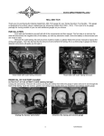
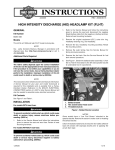
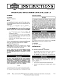
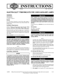
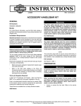
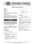
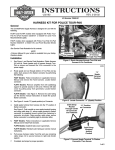
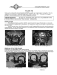
-J03647
REV. 2005-06-15
ADVANCED AUDIO CB ANTENNA KIT (TOUR-PAK MOUNT)
GENERAL
Kit Number
2.
Open the Tour-Pak lid and remove all items from the TourPak base.
3.
Models with rubber mat: Remove the mat.
76414-06
Models with molded liner: Open the map pocket and
remove the acorn nuts with flat washers. Remove the map
pocket and liner.
Models
This kit fits 2006 and later FLHT (Electra Glide®), FLHTC
(Electra Glide Classic), FLHX (Street GlideTM) and FLTR (Road
Glide®) model motorcycles.
is00492
1-1/4 in. (31.8 mm)
2
Additional Parts Required
Unless they have already been fitted:
FLHT models will require the installation of an Advanced Audio
AM/ FM/ CD Radio Kit (Part Number 76412-06), and a TourPak Mount AM/ FM Antenna Kit (Part Number 76317-06).
1-1/2 in.
(38.1 mm)
3
For ALL models, a CB Radio Kit (Part Number 76416-06) is
needed.
9-1/4 in.
(235 mm)
This Kit will will also require the prior installation of a Tour-Pak®.
See a Harley-Davidson dealer for availability of color-matched
King or Chopped Tour-Paks to match your vehicle, and additional items that may be required when mounting the Tour-Pak
to your model.
1
These items are available from a Harley-Davidson Dealer.
The rider's safety depends upon the correct installation
of this kit. Use the appropriate service manual procedures.
If the procedure is not within your capabilities or you do
not have the correct tools, have a Harley-Davidson dealer
perform the installation. Improper installation of this kit
could result in death or serious injury. (00333a)
1. Tour-Pak centerline
2. Drill 17/32 in. (13.5 mm) hole
3. Drill 1/4 in. (6.4 mm) hole
Figure 1. Tour-Pak CB Antenna Drilling Location
NOTE
This instruction sheet references Service Manual information.
A Service Manual for your model motorcycle is required for
this installation and is available from a Harley-Davidson Dealer.
4.
See Figure 1. Measure and determine the center (1) of
the outside rear Tour-Pak wall.
5.
Lay a strip of 2 in. (51 mm) wide masking tape from top
to bottom over the approximate center of the outside rear
Tour-Pak wall.
6.
Harley-Davidson strongly recommends that the antenna be
installed where indicated. In this position the antenna will cause
the least interference with the opening and closing of the TourPak lid.
Very carefully measure again, and mark the center near
the top of the tape strip. Measure and mark the center
near the bottom of the strip. Draw a line from the top mark
to the bottom mark.
7.
Facing the tape, measure 9-1/4 in. (235 mm) from the
center line to the right side of the outside rear Tour-Pak
wall.
Tour-Pak Preparation
8.
Lay a strip of 2 in. (51 mm) wide masking tape from the
top to approximately half way down the outside rear TourPak wall at the 9-1/4 in. (235 mm) distance from the center
line.
Kit Contents
See Figure 4 and Table 1.
INSTALLATION
NOTE
1.
Refer to the Service Manual and follow the instructions
given to remove the right-side saddlebag.
-J03647
1 of 5
9.
Very carefully measure again, and mark the tape 9-1/4 in.
(235 mm) from the center line, near the top of the tape
strip and again near the bottom of the strip. Draw a line
from the top mark to the bottom mark.
if the Tour-Pak interior has a MEDIUM GRAY, GLOSSY
finish (Type 1 Tour-Pak):
a.
10. Measure down 1-1/4 in. (31.8 mm) from the top edge of
the Tour-Pak on the right-side vertical line, and draw a
short horizontal line (2) across the vertical line.
See Figure 2. Measure and determine the center (1)
of the support plate (2) that covers the floor of the
Tour-Pak.
b.
11. Measure down 1-1/2 in. (38.1 mm) from the first horizontal
line, and draw another short horizontal line (3) across the
vertical line.
Lay a strip of 2 in. (51 mm) wide masking tape from
the front to about half-way back down the approximate
center of the support plate.
c.
Very carefully measure again, and mark the center
of the support plate at the front of the tape strip, and
again near the back. Draw a straight line through the
two marks.
12. Mark the center of the crossed lines with a center punch,
then:
a.
drill two 1/8 in. (3 mm) guide holes through the TourPak wall,
d.
Facing the tape, measure 7-1/2 in. (190 mm) from
the center line to the right side floor of the Tour-Pak.
b.
drill a 17/32 in. (13.5 mm) hole through the upper
guide hole, and
e.
c.
drill a 1/4 in. (6.4 mm) hole through the lower guide
hole.
Lay a strip of 2 in. (51 mm) wide masking tape on the
Tour-Pak floor in front of the support plate at the 71/2 in. (190 mm) distance from the center line, from
the support plate to the front wall.
f.
Very carefully measure again, and mark the tape 71/2 in. (190 mm) from the center line, near the front
wall and again near the support plate. Draw a line
between the two marks.
g.
Measure forward 5/8 in. (16 mm) from the front edge
of the support plate, and draw a short line across the
line drawn in the step above.
h.
Mark the center of the crossed lines with a center
punch, then drill a 1/8 in. (3 mm) guide hole through
the Tour-Pak floor.
i.
Lay a strip of 2 in. (51 mm) wide masking tape on the
outer surface of the Tour-Pak floor, centered on the
guide hole. Poke a hole in the tape at the guide hole.
j.
From the underside of the Tour Pak drill a 3/4 in. (19
mm) hole from the outside of the Tour-Pak to the
inside.
k.
Remove the tape. Lightly sand to remove burrs and
sharp edges. Clean the inside and outside Tour-Pak
surfaces of tape residue with a mixture of 50 to 70%
isopropyl alcohol and 30 to 50% distilled water.
13. Remove the tape. Lightly sand to remove burrs and sharp
edges. Clean the Tour-Pak surface of tape residue with a
mixture of 50 to 70% isopropyl alcohol and 30 to 50%
distilled water.
is00574
5/8 in. (16 mm)
2
7-1/2 in.
(190 mm)
3
1
1. Tour-Pak centerline
2. Support plate
3. Drill 3/4 in. (19 mm) hole
Figure 2. CB Antenna Cable Drilling Location (Type 1
Tour-Pak)
14. If the Tour-Pak is drilled for wiring at the lower right
forward edge: Proceed to Step 15.
If the Tour-Pak IS NOT drilled for wiring at the lower
right forward edge, AND:
-J03647
2 of 5
if the Tour-Pak interior has a MATTE BLACK finish
(Type 2 Tour-Pak):
a.
See Figure 3. Measure and determine the center (1)
of the inside front Tour-Pak wall.
b.
Lay a strip of 2 in. (51 mm) wide masking tape from
top to bottom over the approximate center of the
inside front Tour-Pak wall.
c.
Very carefully measure again, and mark the center
near the top of the tape strip. Measure and mark the
center near the bottom of the strip. Draw a line from
the top mark to the bottom mark.
d.
Facing the tape, measure 6-3/8 in. (162 mm) from
the center line to the right side front Tour-Pak wall.
Do not follow the curve of the wall, but measure
straight across. See Figure 3 inset.
e.
Lay a strip of 2 in. (51 mm) wide masking tape from
the bottom to approximately half way up the inside
front Tour-Pak wall at the 6-3/8 in. (162 mm) distance
from the center line.
f.
g.
Very carefully measure again, and mark the tape 63/8 in. (162 mm) straight across from the center line,
near the top of the tape strip and again near the
bottom of the strip. Draw a line from the top mark to
the bottom mark.
For King Tour-Pak: Measure down 7-19/32 in. (193
mm) from the top edge of the Tour-Pak.
For Chopped Tour-Pak: Measure down 4-19/32 in.
(117 mm) from the top edge of the Tour-Pak.
Draw a short horizontal line across the vertical line.
h.
Mark the center of the crossed lines with a center
punch, then drill a 1/8 in. (3 mm) guide hole through
the Tour-Pak front wall.
i.
Lay a strip of masking tape on the outer surface of
the Tour-Pak front wall, centered on the guide hole.
Poke a hole in the tape at the guide hole.
j.
From the outside of the Tour Pak drill a 3/4 in. (19
mm) hole through the guide hole to the inside.
k.
Remove the tape. Lightly sand to remove burrs and
sharp edges. Clean the inside and outside Tour-Pak
surfaces of tape residue with a mixture of 50 to 70%
isopropyl alcohol and 30 to 50% distilled water.
6-3/8 in. (162 mm)
3
is00575
1
2
3
1
4
1. Tour-Pak centerline
2. Measure from top of Tour-Pak base
3. King Tour-Pak; measure 7-19/32 in. (193 mm).
Chopped Tour-Pak; 4-19/32 in. (117 mm)
4. Drill 3/4 in. (19 mm) hole
Figure 3. CB Antenna Cable Drilling Location (Type 2
Tour-Pak)
Antenna Mounting
19. See Figure 4. Obtain the antenna base (3), adapter (4),
and threaded stud (9) from the kit. Insert the adapter into
the hole on the top of the antenna base.
20. Line up the threaded hole in the SIDE of the adapter with
the upper hole on the back side of the base. Insert the
stud into the upper hole on the back side of the base, and
thread the stud into the hole in the adapter. Tighten the
stud securely.
Loading Coil Mounting
21. Assemble the base gasket (5) to the antenna base.
15. Obtain the loading coil (11), truss-head screw (12) and
flanged lock nut (13) from the kit.
22. With the adapter (4) facing up, position the base assembly
over the holes drilled earlier in the outside rear Tour-Pak
wall. Be sure the threaded stud (9) goes through the larger
(top) hole.
16. Remove and discard the right-rear screw and nut that
fasten the support plate to the Tour-Pak floor.
NOTE
Rotate the loading coil so it will fit under the liner when reinstalled on models so equipped.
17. Position the loading coil inside the right-rear corner of the
Tour-Pak, lining up the hole in the bracket with the hole
in the support plate.
18. Holding the flanged lock nut under the Tour-Pak, install
the loading coil with the truss-head screw. Tighten
securely.
-J03647
23. Place the antenna reinforcement plate (6) in position inside
the Tour-Pak. Place the ring terminal coming from the
loading coil over the antenna mast stud. Use the hex nut
with lock washer (10) to attach the loading coil cable to
the stud, but do not fully tighten at this time.
24. Install the TORX® screw (8) and small lockwasher (7)
through the smaller (bottom) hole of the antenna reinforcement plate into the antenna base. Tighten the screw
securely. Tighten the hex nut securely.
3 of 5
25. Thread the antenna mast assembly (1) onto the antenna
base adapter (4), and use a 2 mm hex key to securely
tighten the set screw at the bottom of the mast assembly
to hold it in place.
Antenna Connection
26. Obtain the CB antenna cable (14) and grommet (15) from
the kit.
27. Route the socket end of the antenna cable through the
hole in the lower right front of the Tour-Pak.
28. Mate the socket end of the antenna cable to the pin terminal coming from the loading coil.
29. Make sure enough cable has been routed into the TourPak so that the cable rests flat on the bottom of the TourPak. Capture the antenna cable in the rear clip at the
bottom of the Tour-Pak.
30. Install the grommet onto the antenna cable near the hole
in the Tour-Pak. Carefully work the grommet into the hole
to seal the opening around the cable.
31. Re-install the rubber mat or molded liner. Close the TourPak lid.
32. Route the CB antenna cable along the inside of the luggage rack, forward to the front luggage rack mount. Use
a cable strap (16) from the kit to tie the cable to the frame
rail, underneath the chrome cover.
33. Continue routing the antenna cable forward on the vehicle:
a.
b.
Tuck the cable inboard of the frame tube and avoid
the forward saddlebag guard mounting screw head
so the cable does not get pinched by the seat. Use
four tie straps from the kit to fasten the antenna cable
to the frame tube.
Route the cable along the right side of the battery
cavity and harness tray to the rear of the fuel tank.
Be sure that steering is smooth and free without interference. Interference with steering could result in loss of
vehicle control and death or serious injury. (00371a)
•
Be sure the wires or antenna cable do not pull tight
when handlebars are turned fully to left or right fork
stops.
34. Remove the outer fairing and windshield. Refer to OUTER
FAIRING/ WINDSHIELD REMOVAL in the Service Manual.
35. If not already done, install the AM/ FM radio, AM/ FM
antenna and CB radio per the instructions in those kits.
36. Locate the front end of the CB antenna cable.
37. Route the antenna cable over to the CB module.
38. Plug the antenna cable connector into the back of the CB
module.
39. Tighten the knurled nut to secure the connector to the CB
module.
40. Use tie straps from the kit to fasten the antenna cable to
the existing harnesses inside the fairing.
NOTE
To prevent possible damage to the sound system, verify that
the Ignition/ Light Key Switch is in the OFF position before reinstalling the maxi-fuse.
41. Verify that the Ignition/ Light Key Switch is in the OFF
position. Refer to the Service Manual and follow the
instructions given to re-install the maxi-fuse.
42. Test the CB radio functions for proper operation. If poor
reception or transmission is noted, see SWR ADJUSTMENT, below.
43. Re-install the outer fairing and windshield. Refer to OUTER
FAIRING/ WINDSHIELD INSTALLATION in the Service
Manual.
c.
Remove the fuel tank console attaching hardware
and lift the console from the tank.
d.
Route the antenna cable forward under the right rear
edge of the console, along the right side of the fuel
tank canopy, and out under the right front edge of the
console. Re-install the console, taking care not to
pinch the antenna cable under the console.
SWR ADJUSTMENT
Route the cable down tight to the fuel tank and tie
wrap tight to the main harness, as close to the fuel
tank as possible.
Adjusting the SWR is described in detail in the Harley-Davidson
FLT Electrical Diagnostic Manual.
e.
f.
Continue the antenna cable forward into the fairing,
using tie wraps to fasten to the main harness.
Standing wave ratio (SWR) is a technical term for the procedure
that checks how well the CB transmitter and antenna are
matched. If poor CB reception or transmission is noticed, the
SWR should be checked.
To check SWR, an SWR meter or bridge is required. A HarleyDavidson dealer will either have an SWR meter and the
appropriate adapters, or can direct you to a CB repair shop for
an SWR check.
Since the operating procedures for SWR meters vary, be sure
the operating instructions for the SWR meter being used are
carefully followed.
-J03647
4 of 5
SERVICE PARTS
is00489
1
16
2
4
15
14
5
6
3
2
9
12
11
10
2
7
13
8
Figure 4. Service Parts, CB Tour-Pak Mount Antenna
Table 1. Service Parts Table
Item
Description (Quantity)
Part Number
1
Mast assembly, CB antenna
76250-98
2
•
3248
3
Antenna base
Not Sold Separately
4
Adapter, antenna
Not Sold Separately
5
Gasket, antenna base
76255-86
6
Reinforcement plate
76322-97
7
Lock washer, internal tooth, #10
7118
8
Machine screw, pan head, TORX, #10-32 x 3/4 in.
2576
9
Stud, M5 x 35 mm
3227
Set screw, M4 (3)
10 Nut, with lock washer, M5
7492
11 CB loading coil
76294-98
12 Screw, truss head, 1/4-20 x 1/2 in, chrome
932
13 Lock nut, flanged, 1/4-20
7716
14 CB antenna cable
76319-06
15 Grommet
11486
-J03647
5 of 5