1
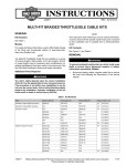
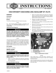
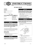
-J03652
REV. 2013-01-30
ADVANCED AUDIO INTERCOM KIT
Kit Contents
GENERAL
Kit Number
Table 1. Kit Contents
76440-06
Description (Quantity)
Models
For model fitment information, see the P&A Retail Catalog or
the Parts and Accessories section of www.harley-davidson.com
(English only).
Additional Parts Required
NOTE
Even if this kit is not being installed by a Harley-Davidson
dealer, the intercom software flash (purchased separately)
must be performed on the radio installed on the motorcycle
at the dealer before the kit is installed.
ALL models will require the additional purchase of EITHER:
•
a Premium Stereo Helmet Headset (Part Number 7714798) OR
•
a Hand-Held CB Microphone Kit (Part Number 76312-98)
Additional equipment will be required for proper installation
of this Intercom Kit on your model motorcycle. See the P&A
Retail Catalog or the Parts and Accessories section of
www.harley-davidson.com (English only) for a list of required
parts or accessories for your model.
Passenger Headset Harness
Not Sold Separately
Tie wrap (10)
10006
INSTALLATION
1.
Have a Harley-Davidson dealer perform the intercom
software flash (purchased separately) to the previously
installed AM/FM/CD Radio.
2.
Refer to the Service Manual and follow the instructions
given to remove the seat and the left-side saddlebag.
3.
Follow the instructions in the Service Manual to remove
the maxi-fuse.
4.
See Figure 1. Obtain the passenger headset harness (5)
from the kit. With the headset receptacle (6) facing forward,
capture the receptacle in the bracket on the underside of
the left-side rear speaker housing.
5.
If the Advanced Audio High-Output Amplifier is
installed under the Tour-Pak: Grasp the tie strap (7) on
the end of the Vinyl spring sleeve (8), and use a tie strap
from the kit to fasten the end of the spring to the lower left
slot on the license plate holder. If stronger headset
receptacle retention is desired, the spring assembly in the
kit can be replaced with spring assembly 76300-06 (purchased separately).
The rider's safety depends upon the correct installation
of this kit. Use the appropriate service manual procedures.
If the procedure is not within your capabilities or you do
not have the correct tools, have a Harley-Davidson dealer
perform the installation. Improper installation of this kit
could result in death or serious injury. (00333a)
NOTE
This instruction sheet references Service Manual information.
A Service Manual for your model motorcycle is required for
this installation and is available from a Harley-Davidson Dealer.
-J03652
Part Number
If no Amplifier is installed: Grasp the tie strap (7) on the
end of the Vinyl spring sleeve (8), and hook the sleeve
and the end of the spring onto the tab at the upper right
of the license plate holder.
6.
Route the harness forward on the vehicle:
a.
along the left-side Tour-Pack support. Use a tie strap
from the kit to fasten the harness to the support.
b.
Continue forward, tucking the harness inboard of the
frame tube and avoiding the forward saddlebag guard
mounting screw head so the harness does not get
pinched by the seat. Use four tie straps from the kit
to fasten the harness to the frame tube.
c.
Route the harness along the left side of the battery
cavity and harness tray to the rear of the fuel tank.
Many Harley-Davidson® Parts & Accessories are made of plastics and metals which can be recycled.
Please dispose of materials responsibly.
1 of 4
is00494
1
9
5
2
3
6
4
8
7
1.
2.
3.
4.
5.
6.
7.
8.
9.
35-place socket housing [28] to AM/ FM radio
6-place pin housing [6A], labelled "Interconnect"
8-place pin housing [76] to passenger headset
12-place pin housing [53] to console pod
Passenger headset harness
Rear headset receptacle
Tie strap on spring and sleeve end
Spring sleeve
8-place socket housing
Figure 1. Harness Connections
If a cruise control switch IS NOT present:
NOTE
If not already installed, the Fairing Speaker Switch and LeftHand Control Switch Assembly (purchased separately, individually or as part of the Communication Switch Kit) must be
installed at this time according to the instructions that follow.
7.
On the fairing cap, remove the inner left side hole plug.
See the FAIRING CAP SWITCHES (FLHTC/U) section in
the Service Manual. Install the fairing speaker switch in
the opening as follows:
If a cruise control switch IS present: See FAIRING CAP
SWITCHES (FLHTC/U) in the Service Manual. Install the
Fairing Speaker Switch (purchased separately or as part
of the Communication Switch Kit) in the opening and
connect the wiring already there.
a.
Obtain the speaker switch adapter wire (purchased
separately or as part of the Communication Switch
Kit) and the butt splice connector included with the
speaker switch.
b.
Refer to SEALED BUTT SPLICE CONNECTORS in
the Service Manual. Splice the adapter wire to the
black/green speaker switch lead.
c.
Insert the terminated end of the adapter wire into
cavity 12 of the fairing cap switch connector [105B]
8.
Remove the original equipment left-hand control switch
assembly per the HANDLEBAR SWITCHES, REMOVAL,
LEFT HANDLEBAR CONTROLS instructions in the Service Manual.
9.
Install the new left-hand control switch assembly (purchased separately or as part of the Communication Switch
Kit).
10. Remove the outer fairing and windshield. Refer to OUTER
FAIRING/WINDSHIELD REMOVAL in the Service Manual.
-J03652
2 of 4
NOTES
INSTALLATION (CONTINUED)
11. ALL models: Install the Console Pod Assembly.
a.
b.
c.
Note the routing of the main harness, fuel level
sender/fuel pump conduit, and fuel vapor vent tube
as they travel beneath the console.
Carefully cut the anchored cable strap securing the
main harness, fuel level sender/fuel pump conduit,
and fuel vapor vent tube to the left side of the frame
backbone.
Open the fuel door on the console. Remove the two
Allen head screws inboard of the rubber bumpers.
These screws secure the console to the clip nuts on
the canopy bracket.
Make sure the rubber molding (new rubber molding 71294-89
for FLHX models) on the bottom of the console is seated
properly along its entire length.
FLHX models: Mount the adhesive-backed metal wire clip
(Part Number 10103) to the underside of the console to hold
the pod harness and Intercom harness.
Mount the plastic wire clip (Part Number 10120) to the underside of the console to hold the fuel vapor vent tube.
12. Install the console to the tank.
a.
All models EXCEPT FLHX: Remove the Allen head
screw to detach the flange at the rear of the console
from the clip nut on the fuel tank weldment.
Route the pod harness and Intercom harness forward
along the left side of the fuel tank canopy and out
under the left front edge of the console. Be sure that
the hoses and wires are not pinched by the console
during installation. Install the filler cap.
FLHX models: Remove the bolt (with flat washer) at
the rear of the fuel tank to release the console
bracket. This also frees the rear of the tank from the
frame backbone.
b.
Remove the two screws that fasten the fuel door to
the console, and remove the door. Remove the hinge
mounting clip, and the hinge pin. Save these parts
for installation.
d.
All models EXCEPT FLHX: Install the Allen head
screw removed earlier to fasten the rear flange of the
console to the clip nut on the fuel tank weldment.
FLHX models: Install the 1/4-20 clip nut (purchased
separately) onto the bracket on the fuel tank. Install
the console extension (also purchased separately)
onto the rear of the console with the button-head
screw (purchased separately) and staked nut.
Lay a clean shop towel on the forward part of the rear
fender. Remove the filler cap from the neck of the fuel
tank.
All models EXCEPT FLHX: Remove the console
and lay it upside down on the shop towel. Install the
filler cap.
ALL models: Tighten the screw to 25-30 in-lbs (2.83.4 Nm).
FLHX models: Remove the console and discard it.
Install the filler cap.
Obtain the new fuel tank console (purchased separately). Install the fuel door to the new console, and
tighten securely.
c.
Open the fuel door on the console. Install the two
Allen head screws to secure the front of the console
to the clip nuts on the canopy bracket. Alternately
tighten the screws to 25-30 in-lbs (2.8-3.4 Nm).
d.
Snap the anchor of a cable strap from the kit into the
hole on the left side of the frame backbone.
Lay the console upside down on the shop towel.
Tighten the cable strap capturing the main harness,
Intercom harness, fuel level sender/fuel pump conduit,
and fuel vapor vent tube. Cut any excess cable strap
material.
Install the bolt (with flat washer) to secure the rear of
the fuel tank to the frame backbone. Tighten the bolt
to 15-20 ft-lbs (20-27 Nm).
e.
Remove the filler cap. Place the console over the filler
neck onto the canopy. Route the Intercom harness
forward under the left rear edge of the console. Route
the cables from beneath the console in the same way
as installed originally.
Feed the pin housing and console pod conduit through
the top of the console, seating the Console Pod
Assembly (purchased separately) in the recess.
e.
Install three Phillips screws (purchased separately)
from the underside to secure the pod to the console.
Alternately tighten the screws to 6-11 in-lbs (0.7-1.2
Nm).
Route the pod harness and Intercom harness down
tight to the fuel tank and tie wrap tight to the main
harness, as close to the fuel tank as possible.
f.
Continue the harnesses forward into the fairing, using
tie wraps to fasten to the main harness.
Route the pod harness toward the front of the console.
Do not kink or pinch the fuel overflow line when installing
console. A blocked line can cause an overfilled tank to
leak. Gasoline is extremely flammable and highly
explosive, which could result in death or serious injury.
(00264a)
-J03652
Be sure that steering is smooth and free without interference. Interference with steering could result in loss of
vehicle control and death or serious injury. (00371a)
•
Be sure wires do not pull tight when handlebars are
turned fully to left or right fork stops.
3 of 4
13. Obtain the overlay harness (purchased separately), unless
already installed.
a.
See Figure 1. Plug the socket housing (9) on the end
of the intercom harness into the overlay harness 8place pin housing [76] (item 3)
b.
Plug the 35-place radio socket housing [28] (1) into
the radio.
c.
Locate the interconnect harness audio connector [6B]
near the back of the radio. Plug 6-way pin housing
[6A] (2) on the overlay harness into socket housing
[6B].
d.
Plug the overlay harness 12-place pin housing (4)
labeled "Intercom" [53] into the socket housing coming
from the console pod.
14. Use tie straps from the kit to fasten the intercom and
overlay harnesses to the existing harnesses inside the
fairing.
-J03652
15. Verify that the Ignition/Light Key Switch is in the OFF
position. Refer to the service manual and follow the
instructions given to install the maxi-fuse.
16. Test the intercom and the rest of the sound system for
proper operation.
17. Install the outer fairing and windshield. Refer to OUTER
FAIRING/ WINDSHIELD INSTALLATION in the Service
Manual.
18. Refer to the Service Manual, and follow the instructions
given to install the left-side saddlebag and the seat.
After installing seat, pull upward on seat to be sure it is
locked in position. While riding, a loose seat can shift
causing loss of control, which could result in death or
serious injury. (00070b)
4 of 4