1
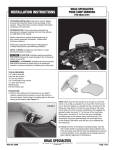
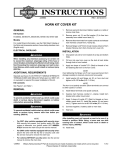
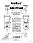
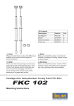
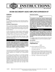
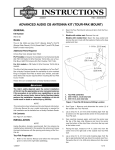
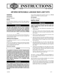
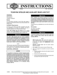
-J05169
REV. 2011-09-23
BOOM! AUDIO NAVIGATION INTERFACE MODULE KIT
Electrical Overload
GENERAL
Kit Number
76000024, 76000024A
Models
For model fitment information, see the P&A retail catalog or
the Parts and Accessories section of www.harley-davidson.com
(English only).
A Road Tech Zumo 665 GPS Kit (Part No. 76000014) is
required. This item is available from a Harley-Davidson dealer.
This kit can be used with a Road Tech Zumo 660 GPS Kit
(Part No. 92115-09) after a software update to 3.70 or later.
•
The software version can be found at the upper right
corner of the Zumo screen by selecting Tools>Settings>System>About.
•
Go to www.harley-davidson.com/zumo and click on "Road
Tech zumo 660 GPS Navigator", and then the "Downloads"
tab to obtain the latest version.
•
Go to "zumo 660 software updates" and use the "Web
Updater" link.
This kit is not compatible with the Advanced Audio Bluetooth®
Hands-Free Cell Phone Interface (Part No. 76408-06).
Installation Requirements
FLHT models will require prior installation of an Advanced
Audio AM/FM/CD Radio Kit (Part No. 76412-06) and an AM/FM
Antenna Kit (Part No. 76325-06 or 76317-06).
It is possible to overload your vehicle's charging system
by adding too many electrical accessories. If the combined
electrical accessories operating at any one time consume
more electrical current than the vehicle's charging system
can produce, the electrical consumption can discharge
the battery and cause damage to the vehicle's electrical
system. See an authorized Harley-Davidson dealer for
advice about the amount of current consumed by additional electrical accessories or for necessary wiring
changes. (00211c)
When installing any electrical accessory, be certain not
to exceed the maximum amperage rating of the fuse or
circuit breaker protecting the affected circuit being modified. Exceeding the maximum amperage can lead to electrical failures, which could result in death or serious injury.
(00310a)
The Navigation Interface Module (NIM) requires up to 30 milliamps additional current from the electrical system.
Kit Contents
See Figure 5 and Table 1.
PREPARATION
NOTE
FLHT/C, FLHX, FLTR/X and FLHXXX Models WITHOUT
Non-Ultra Overlay Harness (Part No. 70169-06) installed
will require separate purchase of a Connector Kit (Part No.
69200033).
For vehicles equipped with security siren:
These items are available from a Harley-Davidson dealer.
The rider's safety depends upon the correct installation
of this kit. Use the appropriate service manual procedures.
If the procedure is not within your capabilities or you do
not have the correct tools, have a Harley-Davidson dealer
perform the installation. Improper installation of this kit
could result in death or serious injury. (00333a)
NOTE
•
2007 and later: Verify that the Hands-Free Fob is present.
•
2006 and earlier: Disarm the siren with the key fob.
•
ALL vehicles: Turn the ignition key switch to IGNITION.
To prevent accidental vehicle start-up, which could cause
death or serious injury, remove main fuse before proceeding. (00251b)
1.
See the service manual and remove the main fuse.
2.
Remove the outer fairing and windshield per the service
manual.
This instruction sheet refers to service manual information. A
service manual for this year/model motorcycle is required for
this installation and is available from a Harley-Davidson dealer.
-J05169
Many Harley-Davidson® Parts & Accessories are made of plastics and metals which can be recycled.
Please dispose of materials responsibly.
1 of 4
MOUNTING BRACKET INSTALLATION
3.
FLH Models (Except Trike)
1.
See Figure 1. Remove the fairing mounting screw (4) at
the top of the right side fairing support bracket (3).
Trike Models
1.
is06571
5
4
1
Fasten the module bracket through the radio carrier
bracket to the radio with the screws removed earlier.
Tighten to 35-45 in-lb (4.0-5.1 Nm).
See Figure 3. Locate the module mounting bracket (4)
attached to the right side fairing support bracket (3).
is06576
4
2
3
3
1.
2.
3.
4.
5.
Navigation module
Unused connector (if equipped)
Right-side fairing support bracket
Fairing mounting screw
Navigation module mounting bracket
2
1.
2.
3.
4.
Figure 1. Module Bracket Installation (FLH Models)
2.
Clip the module bracket (5) over the top edge of the support bracket.
3.
Fasten the module bracket through the support bracket
to the inner fairing with the screw removed earlier. Tighten
to 20-30 in-lb (2.3-3.4 Nm).
FLT Models
1.
See Figure 2. Remove the right-side radio mounting
screws (4).
2.
Position the module bracket (5) to the side of the radio
carrier bracket (3), lining up the two holes in the module
bracket with the radio mounting holes.
is06573
NAVIGATION INTERFACE MODULE
INSTALLATION
1.
3
2
Navigation module
Unused connector (if equipped)
Radio carrier bracket
Radio mounting screw (2)
Navigation module mounting bracket
Figure 2. Module Bracket Installation (FLT Models)
-J05169
See Figure 1, Figure 2 or Figure 3.Install the Navigation
Interface Module (NIM) (1) on the underside of the
module bracket.
a.
Clean the underside of the module bracket with a 5050 mixture of isopropyl alcohol and distilled water.
Allow to dry thoroughly.
b.
Remove the liner from the adhesive backing of the
module. Carefully position the module to the module
bracket with the six-way connector toward the front
of the vehicle.
Press the module squarely and firmly onto the
bracket, and hold pressure for about 60 seconds.
After releasing pressure, avoid direct contact with the
module for about 20 minutes.
5
1.
2.
3.
4.
5.
Navigation module
Unused connector (if equipped)
Right-side fairing support bracket
Navigation module mounting bracket
Figure 3. Module Installation (Trike Models)
4
1
1
2.
See the wiring diagrams in the service manual appendix.
Locate the Audio Harness connector [6] near the back of
the radio, and separate the six-way connector halves [6A]
and [6B].
3.
Models WITHOUT 35-way connector on back of radio:
Get the Connector Kit (Part No. 69200033, sold separately), and install the wire terminals and seal plugs per
the instructions in that kit.
Models WITH 35-way connector on back of radio: See
Figure 4 and Figure 5. Unplug the 35-way connector [28B]
from the back of the radio. Follow instructions in the service manual appendix to remove the seal pins from cavities
4, 8, 19, 27 and 31.
2 of 4
Insert the five terminated wires from the iPod/Navigation
Interface Module (NIM) harness (2) into connector [28B]
as follows:
•
Insert the red/blue wire terminal into cavity 4.
•
Insert the tan/red wire terminal into cavity 8.
•
Insert the violet/gray wire terminal into cavity 19.
•
Insert the black/blue wire terminal into cavity 27.
•
Insert the tan/blue wire terminal into cavity 31.
4.
For ALL installations: Mate the six-way connectors [6A]
and [6B] of the iPod/NIM harness to connectors [6B] on
the vehicle interconnect harness and [6A] on the vehicle
audio harness.
5.
Plug the six-way connector [275B] of the iPod/NIM harness
into the NIM interface module (1) connector [275A].
NOTE
Be sure to check that all socket terminals are fully seated and
locked into the 35-way socket housing [28B] before plugging
back into the radio.
6.
Plug connector [28B] into the back of the radio.
7.
If an iPod Interface Module is also installed, see the
instructions in that kit for detailed mounting and electrical
connections.
If an iPod Interface Module is not installed, insert the
cavity seal plugs (4) into the loose eight-way housing (3)
from the kit.
Install the eight-way housing on the unused pin housing
[274B] of the iPod/NIM harness.
8.
If the Zumo is not intended to be used as an audio device
(MP3 or XM) then the audio Y-harness cable is not
required. Skip Steps 9 through 14, and connect the single
pin connector on the NIM module directly to the "AUDIOOUT" socket connector coming from the Zumo mount.
If the Zumo will be used as an audio device, proceed to
Step 9.
NOTE
The audio Y-harness should be doubled back on itself at each
of the three connection points to act as a strain relief.
9.
Plug the single pin connector on the NIM module into one
of the socket connectors on the audio Y-harness cable
(5). The pin will lock to the cable port with an audible
"click".
10. Route the remaining audio Y-harness cable socket connector and connect it to the audio cable from the Zumo
GPS Kit.
11. Route the audio Y-harness cable pin connector and connect it to the "AUDIO-OUT" socket connector coming from
the Zumo mount.
12. Use cable straps (6) from the kit to fasten the iPod/NIM
harness and the NIM cable to the vehicle harnesses inside
the fairing.
-J05169
13. Route the audio cable from the Zumo GPS Kit out of the
inner fairing through the hole for the handlebars. Use a
clip from the Zumo kit to retain the cable along the inner
fairing.
NOTE
When installing the jack plug to the radio port socket:
•
Roll back the outer lip of the rubber seal.
•
Install the plug into the AUX port on the front of the radio
unit.
•
Gently roll the seal back to its original shape to form a seal
over the radio unit port.
This will help eliminate "spring-back" of the plug out of the
socket.
14. Plug the 3.5 mm stereo jack (with rubber boot attached)
on the audio cable into the AUX port on the front of the
radio.
RETURN TO SERVICE
NOTE
To prevent possible damage to the sound system, verify that
the ignition key switch is in the OFF position before installing
the main fuse.
1.
See the service manual and install the main fuse.
2.
Plug the NIM cable connector into the NIM.
3.
Turn the ignition key switch ON, and test the NIM for
proper operation.
4.
Install the outer fairing and windshield per service manual
instructions.
IN USE
Set volume levels and other controls on audio and electronic devices before riding. Distractions can lead to loss
of control, resulting in death or serious injury. (00088b)
See the Zumo owner's manual for information on setting the
navigation volume level.
Bluetooth Settings for Zumo Device:
The Zumo's Bluetooth and Audio Out settings should be
handled in this manner:
•
When a BT headset is paired with the zumo, select Main
Menu>Volume>Audio Output>Headphone .
•
When no BT headset is paired with the zumo, disable the
BT pairing even for mobile phones by selecting Main
Menu>Tools>Settings>Bluetooth>Disabled.
the speaker selector switch should be in the "a" (illuminated)
rearward position to hear navigation prompts over the vehicle
speakers.
3 of 4
1
2
3
4
5
6
7
8
9
10
11
12
13
14
15
16
17
18
19
20
21
22
23
24
25
26
27
28
29
30
31
32
33
34
35
is06564
1
2
3
4
5
6
7
8
9
10
11
12
13
14
15
16
17
18
19
20
21
22
23
24
25
26
27
28
29
30
31
32
33
34
35
BK/GN
SP4
BK/GN
BK/GN
Y/V
R/O
R/B
E
R/O
SP3
Y/V
SP1
Y/V
Y/O
TN/R
SP2
Y/O
V/GY
BK/BE
TN/BE
[274B]
1 2 3 4 5 6 7 8
1 2 3 4 5 6
[28B]
6
5
4
3
2
6
5
4
3
2
1
1
[275B]
BK/GN
BK/GN
Y/V
Y/O
Y/V
Y/O
R/O
BE/Y
V/GY
[6B] [6A]
6
5
4
3
2
6
5
4
3
2
1
1
[6B] [6A]
Figure 4. Wiring Diagram, iPod/Navigation Interface Module
SERVICE PARTS
is06568
8
6
[274B]
4
7
3
[6A]
[28B]
2
[275A]
[6B]
1
5
[275B]
Figure 5. Service Parts, Navigation Interface Module
Table 1. Service Parts
Item
Description (Quantity)
Part Number
1
Module, Navigation Interface (NIM)
83537-11A
2
Harness, iPod/NIM
76477-10
3
Pin housing, eight-way, Deutsch DTM, black
74108-98BK
4
Seal pin (8)
74195-98
5
Y-Harness, audio
69200023
6
Cable strap (4)
10006
7
Bracket, NIM mounting (FLH models)
76455-06
8
Bracket, NIM mounting (FLT models)
83277-11
-J05169
4 of 4