1
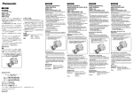
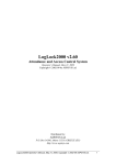
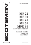
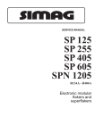
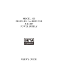
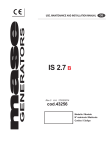
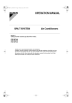
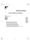
Page 1
Page 1
SERVICE MANUAL
MF 82
VERSIONE R 134 A / R 404 A
Modular superflakers
MS 1000.28 REV. 07/01
Page 2
Page 2
TO BE USED JUST
BY THE INSTALLER
Page 3
Page 3
TABLE OF
CONTENTS
Section I
Table of contents
Specifications
Section IV
6
6
6
6
6
7
7
7
8
9
10-11
OPERATING INSTRUCTIONS
Pre-start inspection
Start up
Section III
3
4-5
GENERAL INFORMATION AND INSTALLATION
Introduction
Description
Sealed refrigerant system
Storage bin or ice room
Unpacking and iInspection
Location and levelling
Electrical connection
Water supply and drain connection
Remote condenser and pre-charged line
Final check list
Installation practice
Section II
page
12
12
PRINCIPLES OF OPERATION - HOW IT WORKS
ICE MAKER
Water
Ice
Refrigeration
ELECTRICAL/REFRIGERATION
14
14
14
14
15-16
ADJUSTMENT, REMOVAL &
REPLACEMENT PROCEDURES
17-18-19-20-21
Section V
SERVICE DIAGNOSIS
Section VI
WIRING DIAGRAMS
Section VII
MAINTENANCE AND CLEANING INSTRUCTIONS
22-23
24-25-26
27-28
Page 4
Page 4
SPECIFICATIONS
MF 82 - AIR & WATER COOLED MODEL
Important operating requirements:
MINIMUM
MAXIMUM
• Air temperature
10°C (50°F)
38°C (100°F)
• Water temperature
5°C (40°F)
38°C (100°F)
• Water pressures 1, 5 atm (20 lbs) gauge
• Electrical voltage variation
• voltage rating
specified on
nameplate
-10%
+10%
Extended periods of operation exceeding these limitations
constitutes misuse under the terms of Scotsman
Manufacturer's Limited Warranty, resulting in a loss of
warranty coverage.
We reserve the right to make product improvement at any
time. Specifications and design are subject to change
without notice.
ice making capacity
AIR COOLED MODELS
WATER COOLED MODELS
2500
10-21
2300
32
2100
38
1900
1700
1500
ICE PRODUCED PER 24 HRS.
°C
AMBIENT TEMPERATURE
Kg.
2700
AMBIENT TEMPERATURE
ICE PRODUCED PER 24 HRS.
Kg.
2700
2500
2300
2100
1900
1700
1500
38
32
27
21
15
10
WATER TEMPERATURE
5 °C
38
32
27
21
15
10
5 °C
WATER TEMPERATURE
NOTE. Daily ice capacity is directly related to condenser air and water inlet temperature, water
temperature to make ice - and age of machine.
To keep your MF 82 performing at its maximum capacity it is necessary to perform periodic
maintenance as outlined on page 27 of this manual.
Page 5
Page 5
SPECIFICATIONS (CONT'D)
➀
➁
➂
√
➄
≈
∆
➇
➈
➉
11
➉
WATER OUTLET
WATER OUTLET - WATER COOLED ONLY
WATER INLET - WATER COOLED ONLY
WATER INLET
CORD SET
MIN SPACE FOR CONNECTION
MIN SPACE FOR PROPER VENTILATION
GAS LINE CONNECTION
LIQUID LINE CONNECTION
CORDSET - REMOTE CONDENSER
MIN SPACE FOR CONNECTIONS
Dimensions:
HEIGHT:
WIDTH:
DEPTH:
NET WEIGHT:
1300 mm (51-1/4")
1073 mm (42-1/4")
774 mm (30-1/2")
407 Kg - MF 82 - A.
387 Kg - MF 82 - W
MF 82 FLAKER - MACHINE SPECIFICATIONS
Model
Cond. unit
Finish
MF 82 AS
MF 82 WS
Air
Water
Stainless Steel
Basic electr.
Air Cooled
Air Cooled
Water Cooled
Air Cooled
230/50/3+N
400/50/3+N
230/50/3+N
400/50/3+N
* At 15°C (60°F) water temperature
Amps
***
17
***
14
Refr.
Compr. HP
5
Electric power cons.
Kwh per 24 HR
R 404 A
170
R 404 A
Water req.
lt/24 HR
2400*
26500*
Nr. of wires
***
5 x 2.5 m/m2
***
5 x 2.5 m/m2
Page 6
Page 6
SECTION I
GENERAL INFORMATION & INSTALLATION
INTRODUCTION
This manual provides the specifications and the
step-by-step procedures for the installation, startup, operation and maintenance and cleaning of
the SCOTSMAN Model MF 82 Flaker.
The Model MF 82 is a quality designed,
engineered, constructed and throughly tested
icemaking system, providing the utmost in
flexibility to fit the needs of a particular user.
DESCRIPTION
The Scotsman MF 82 - continuous flow ice
maker - consists of one large capacity flake ice
making system contained within a compact
cabinet which can be in enamel finish or entirely
in stainless steel. The flake ice produced is
extruded through an ice discharge opening
provided in the rear side of the unit. If the unit
location requires it, the ice spout can be
positioned, as well, to discharge the ice out
through a second opening provided in the left
side of the cabinet. All panels are removable to
allow easy access to electrical and mechanical
components for cleaning and maintenance.
UNPACKING AND INSPECTION
1. Call your authorized SCOTSMAN
Distributor or Dealer, for proper installation.
2. Visually inspect the exterior of the shipping
container and skid and any severe damage
noted, should be reported to the delivering carrier;
and, a concealed damage claim filled in subjetct
to internal inspection, with carrier representative
present.
3. Remove the packing, and remove the
shipping bolts and the shipping base or skid.
4. When necessary, install the leg levelers in
the cabinet base sockets; then, raise the cabinet
to the upright position.
5. Remove screws and shipping tape, and all
doors and service panels from the cabinet, and
inspect for any concealed damage.
Notify carrier of any concealed damage claims,
as stated in step 2 above.
6. Remove all internal support packing, tape
and wires in machinery compartment.
SEALED REFRIGERANT SYSTEM
To provide quite efficient operation of the ice
maker, the compressor is mounted on rubber
grommets. The water cooled models have a
tube within a tube condenser with water regulating
valve for correct condensing water flow.
The air cooled model has a built-in condenser
with four fan motors, controlled by two pressure
controls. The freezer auger is driven by a gear
motor assy.
The refrigerant used is R 404 A controlled by an
automatic expansion valve.
On request the MF 82 cal also be supplied with
remote condenser and copper refrigerant lines.
7. Check that refrigerant lines do not rub or
touch lines or other surfaces, and that fan blades,
if any, move freely.
8. Check that the Compressor is snug on all
mounting pads.
9. Use clean damp cloth or disposable paper
wiper to pipe clean the exterior surfaces of the
cabinets.
10. See DATAPLATE on the cabinet base and
check that the location source voltage corresponds with the voltage specified on the
dateplate.
STORAGE BIN OR ICE ROOM
Since the MF 82 is a continuous flow type ice
maker and does not have its own attached
storage bin, it is necessary to use an auxiliary bin
or prefabricated ice room for appropriate ice
storage. An insulated ice storage bin or room is
always required, then - according to ice
applications - this can be refrigerated or nonrefrigerated; a weight/volume ratio of 1,8 m3 per
ton must be taken into consideration for correct
ice storage room design which, in any case,
should be dimensioned to accomodate a
minimum of 16 hrs. ice production.
CAUTION. Unproper voltage supplied to
the ice Maker will void your parts
replacement program.
11. Remove the Manufacturer’s Registration
Card from the User Manual and fill in all spaces
including: Model Number and Serial Number
taken from the aluminium plate.
Forward the completed, self addressed,
registration card to the Frimont Factory.
Page 7
Page 7
LOCATION AND LEVELLING
ELECTRICAL CONNECTION
WARNING. This unit must be installed in
an area where it will not freeze and
protected from the elements such as wind,
rain, water spray or drip. Ambient temperature limitations are: 10°C (50°F)
minimum and 38°C (100°F) maximum,
while water temperature limitation are:
5°C (40°F) minimum and 38°C (100°F)
maximum.
Ambient and water temperature exceeding
these limitations may result in machine
malfunction and the loss of warranty
coverage.
See machine electrical specifications in Unit
Nameplate and at page 3 of this Service Manual
to determine wire size to be used for electrical
supply. This unit must be grounded according to
all Electrical Codes and local ordinances. Provide
a fuse disconnect box within sight and easyreach of the ice maker. Use delayed action fuses
on all terminals.
The maximum allowable voltage variations should
not exceed ten percent of the nameplate rating,
even under starting conditions. Low voltages can
cause erratic operation and may be responsible
for serious damages to the overload switch and
motor winding.
Make sure that the structure on which the ice
maker will be located be on a solid footing and
supports at least 1000 Kgs.
This ice maker is designed for free standing
application only. Do not built it in. Make sure that
location site is well ventilated to ensure correct
operation of air-cooled models that have the
condenser directly behind the front panel. Also
allow 20 cm clearence in back and both side of
the ice maker to be able to easily perform service
inspections and operations.
WARNING. The compressor is equipped
with a crankcase heater which has to to
energized even when the ice maker is
switched-off. So, make sure to connect
the unit with the compressor crankcase
heater constantly energized. After long
inoperative periods remember to give
current to the heater 4 hours before the
ice maker start-up.
1. Erection - For elevation of machine to its
stand or location, chain falls or fork lifttrucks
should be used. Chain falls can be hooker up to
the machine for upper corners holes provided for
this sort of operation.
WATER SUPPLY AND DRAIN CONNECTIONS
2. Position the MF 82 in the selected permanent
location and level the cabinet on both the left-to
right anf front-to-rear direction.
3. Ice chute extension or ice deflector - if not
pre-set - must be arranged to convey the ice from
the outlet of the machine to the ice storage area.
Stainless steel is an excellent material where its
cost is not prohibitive. Angles or edges of less
than 45° should not be used. Ice will cling to the
surface and either melt excessively or jam in the
ice chute. The sharper the drop, the better.
If straight down, do not insulate unless necessary.
Ice chute and or ice deflector end - whenever
possible - should be preset with grommeted
holes so that bin thermostat capillary tube can be
inserted in them to be correctly positioned.
4. Thermostat capillary tube must be positioned so that its end extends out the ice chute
opening or the ice deflector and get easily in
contact with the cone formed by the ice deposited
in the storage room, before - anyway - that ice
builds-up in the chute.
Thermostat capillary tube is coiled behind the
control box, it must be routed to follow the ice
chute or ice deflector and protrude for a certain
extension beyond the ice discharge opening in
the storage room. Use caution when routing this
capillary to prevent kink or to bent it excessively.
Coil excess capillary inside ice maker cabinet.
Tape coil to prevent vibration againt another part.
A. AIR-COOLED MODELS: The recommended water supply line is a 3/4 inch O.D. fitting.
Connect to cold water supply line with standard
plumbing fittings, with a shutoff valve installed in
an accessible place between the water supply
and the Cabinet.
A wire mesh strainer is provided inside the fitting.
The strainer protects against large particles of
rust, scale, etc., which may be loosened in the
water supply pipe at the time of installation.
In some cases, a plumbing permit and services
of a licensed plumber will be required.
CAUTION - This ice maker is equipped
with a low water pressure safety device
which, in the event of low water pressure,
will automatically stop the ice maker to
prevent damage. The ice maker will
automatically restart with increased water
pressure.
This ice maker will not operate properly
when water supply temperatures are
below 5°C (40°F) and above 40°C (100°F).
B. WATER-COOLED MODELS: On WaterCooled models a separate connection, to the
Condenser is required. A 3/4 inch O.D. fitting is
provided for a separate water inlet line to be
connected and a separate drain line to be
connected.
Page 8
Page 8
NOTE. - The WARNING, in the text above
for the Air-Cooled models equally applies
for the Water-Cooled models. In both type
installations, water supply must be
installed to conform with local plumbing
codes. In some cases, a plumbing permit
and services of a licensed plumber will be
required.
C. DRAIN CONNECTIONS: All drains are
gravity type and must be 1/4-inch per foot on
horizontal runs. The drains to be installed to
conform with local code. The drain receptacle
should be an open, trapped or vented construction.
Connect a drain line to 3/4-inch I.D. tube from the
freezer drip pan and a separate drain line to 3/4inch O.D. drain fitting from the Water-Cooled
Condenser, on Water-Cooled models.
REMOTE CONDENSER AND PRECHARGED
REFRIGERANT LINES INSTALLATION
A.
Location considerations:
practices of builting standards that conforms to
and meets the local building code requirements,
in your area.
2. Remove control box cover from remote
condenser and connect the electrical power line
coming from the unit to the wires of the fan motor
by means of the connecting terminal board placed
into the control box following the wires color fitted
on the same.
D.
1. The set of pre-charged refrigerant lines
consists of a 3/8 inch inside diameter, self-sealing
liquid line and a 3/4-inch inside diameter, selfsealing discharge line.
2. When possible, route the maximum length
of the pre-charged refrigerant lines in the building,
with the minimum lenght outside, to prevent
vandalism and to minimize the condenser effect
that exposed lines can produce in cold weather.
Insulate lines that with be exposed to outside
temperatures that will be below freezing, for
extended periods of time.
1. Limited to 6 metres the length of precharged
refrigerant line from the left side of the icemaker
to the remote condenser.
CAUTION
1. Each coupling on the precharged
refrigerant lines, is self-sealing and should
be tightened 1/4 - turn more than snug
tight. ALWAYS USE TWO WRENCHES
WHEN TIGHTENING THESE FITTINGS,
ONE AS BACKUP WRENCH TO PREVENT
TWISTING OF TUBING AND POSSIBLE
KINKING OR LINE RUPTURE.
2. Maximum vertical rise of 3 metres between
the icemaker and the remote condenser;
3. Best available location, protected from the
extremes of dirt, dust, rain, sun ans winds.
B.
Unpacking and inspection:
1. Visually inspect the exterior of the shipping
container and any severe damage noted, ahould
be reported to delivering carrier; and a concealed
damage claim filled subject to internal inspection,
with carrier representative present.
2. Uncrate the remote condenser and
precharged refrigerant linea and inspect for any
concealed damage. Notify carrier of any
concealed damage claims, as stated in step 1,
above.
Pre-charged refrigerant lines
3. Connect the 3/8-inch diameter refrigerant
line coupling, to the remote condenser refrigerant
fitting and to the refrigerant fitting on the right side
of the Icemaker chassis.
4. Connect the 3/4-inch diameter refrigerant
line coupling, to the remote condenser refrigerant
fitting and to the refrigerant fitting on the right side
of the Icemaker chassis.
3. Check that the pre-charged refrigerant linea are intact, not kinked, and that there is no
sealed puncture or loss of refrigerant.
E. Excess length of pre-charged refrigerant
lines: at installations where the Icemaker chassis
- to - remote condenser refrigerant line path is
substantially less then the length of pre-charged
refrigerant lines to be installed, route and dress
the excess refrigerant line as follows.
C.
1.
Remote condenser - wall attachment:
1. Install and attach the remote condenser to
the wall of the building, using the methods and
Follow straight line routing, when possible.
2. Retain excess pre-charged refrigerant line
inside the building.
Page 9
Page 9
3. Spiral the excess length of the precharged
refrigerant line, in the best selected inside
location, and in a manner that prevents
refrigerant trapping.
FINAL CHECK LIST
1.
Is the Cabinet level? (IMPORTANT)
2. Have all electrical and piping connections
been made?
3. Is there an electrical service disconnect
within sight of the installed machine?
Has the voltage been tested and checked against
the nameplate rating?
4. Is the water supply line shutoff valve installed
near the machine.
5. Have all the wires been checked for
looseness and thightness.
6. Have the Compressor hold down nuts been
checked, to be sure the Compressor is snug on
the mounting pads.
7. Has the owner/user been instructed on how
to operate the Icemaker.
8. Has the Manufacturer’s registration Card
been properly filled out? Check for correct Model
and serial numbers from Serial nameplate, then
mail the completed card to the FRIMONT factory.
9. Check all refrigerant linea and conduit lines,
to guard against vibration or rubbing and possible
failure.
10. Is there at last 20 cm. clearance behind and
around Cabinet for proper air circulation?
11. Is the Icemaker installed indoor in a location
where ambient temperatures are a Minimum of
10°C (50-degrees F.) all year around?
12. Has water supply pressure been checked
to insure a minimum of 1 atm (14 Psi).
13. Is the remote condenser installed per local
building codes, and in a place where it has
adequate ventilation and minimal solar heat gain.
14. Verify that unit lighted switch is in the OFF
position.
CAUTION - DO NOT kink or brimp the
refrigerant lines. DO NOT bend the excess
refrigerant lines in a vertical loop(s), which
allow trapping of refrigerant in LOW
sections, during OFF time. Bend and
shape the excess refrigerant lines in
VERTICAL spirals, not HORIZONTAL
spirals. See Figure above.
15. Switch the main disconnect switch on power
line in the ON position to energize the compressor
crankcase heater well in advance the start-up.
16. Verify that dial of delay timer, in control box,
is set on 5 minutes.
17. Has the owner been given name and
telephone number of the authorized SCOTSMAN
Service Agency
Page 10
Page 10
INSTALLATION PRACTICE
Page 11
Page 11
INSTALLATION PRACTICE
➀
➁
➂
√
➄
≈
POWER LINE
HAND DISCONNECT SWITCH
CONTROL TIMER (OPTIONAL)
WATER SUPPLY LINE
HAND SHUT - OFF VALVE
WATER FILTER (NOT SUPPLIED)
∆
➇
➈
WATER INLET LINE W / SEPARATE SHUT - OFF VALVES
WATER DRAIN LINE
OPEN VENTED DRAIN
Page 12
Page 12
SECTION II
OPERATING INSTRUCTIONS
PRE-START INSPECTION
1. Make sure that the electrical power has
been on for at least 4 hours and that compressor
crankcase is warm.
2. From unit left side check to see, through
appropriate sight glass, the oil level in gear box
and also the oil level in compressor crankcase.
3. Verify that drive motor current limiter
LOVATO LA3E, located in control box on right
side of contactor, has the AMPs setting knob (top
red knob) positioned on 0.4 the second red
setting screw on two sec. and the blue setting
screw on zero INHIBITION setting.
START-UP
The following procedure can only be started after
pre-start inspection has been properly completed.
1. Open the water supply line shutoff valve.
Observe that water enters the water reservoir,
fills the tube from the reservoir to the evaporator
and then shut-off. Check for leaks.
2. Temporary set dial of delay timer to zero
position.
3. Press unit lighted switch to ON. Unit will
start operating. Verify immediately if auger drive
motor turns the auger (coupling) in
counterclockwise directions.
WARNING - The evaporator auger drive
motor is threephase, so, at the unit
start-up, care must be taken to ensure of
the correct rotation direction of auger. In
case of wrong rotation interchange the
phases by interchanging the lead wire
connections of main cord.
AUGER MUST TURN COUNTERCLOCKWISE.
4. If auger drive motor is rotating correctly,
move the timer delay to 5 minutes position. Unit
must be on delay control set on 5 min. and will
always resume operation when 5 min. delay is
elapsed.
5. After two or three minutes of unit operation
observe that flaked ice begins to drop out in the
ice spout. In the evant that the drive motor
current limiter will cut-out unit operation, DO
NOT BE ALARMED. Unit will automatically
resume operation after 5 minutes.
6. Let the system operate for about 30 minutes.
Check for any excess noises beyond normal
compressor noise:
a) Fan noises when Air-Cooled: blades
touch other surfaces; blades bent; out of
balance.
b) Vibrating type from touching lines.
c) Chattering: lack of water in Freezer.
d) Compressor loose at one or more holddown bolts.
7. If desired, the low side pressure can be
checked, it should be 1.9 atm (27 psi).
Check to see through liquid sight glass for correct
refrigerant flow and charge.
8. Hold a handful of ice around the ice storage
bin thermostatic control bulb to test shut-off.
Less than one minute is about normal for bulb
shut-off function to cause the ice maker to
stop.
Remember that unit will resume operation after
5 minutes that bin thermostat has closed its
contacts.
Page 13
NOTE. When unit is on 5 minutes delay, the
light of unit switch glows, signalling that unit
is under power.
9. There are no adjustments to make, so
replace the panels.
Page 13
10. Throughly explain the owner/user the
significant specifications of the ice maker, the
start-up, operation and attention to pay going
through the procedures in the operating
instructions. Answer all questions about the ice
maker, by the owner, and inform the owner of the
name and telephone number of the authorized
SCOTSMAN Service Agency serving him.
Page 14
Page 14
SECTION III
PRINCIPLES OF OPERATION - How it Works
ICEMAKER:
Water
The water supply flows from the building source
through the inline water strainer, enters at the
Cabinet fitting and on to the Water Reservoir.
The water Reservoir functions to maintain a
constant water level inside the Freezer Assembly.
Water from the Water Reservoir enters at the
bottom of the freezer Assembly and is changed
into ice by low temperatures inside the freezer.
Ice
A stainless steel Auger within the Freezer is
powered by a separate drive motor through a
speed reducer and the rotating Auger carriers
the ice upward to the Ice Breaker assy where
excess water is pressed out of the ice, as it is
extruded or flaked out through the Ice breaker.
The flake ice into spout in diverted out through
the ice discharge opening. Moving the manual
ON-OFF toggle switch, to the ON position starts
after 5 minutes the automatic and continuous
icemaking process. When the Ice touches the
Thermostatic Control Bulb, the sensing bulb
shuts off the icemaking process.
Refrigeration
Beginning at the compressor, the refrigerant R
404 A is compressed into a high temperature
gas.
The discharge line directs this gas to the
condenser. At the condenser (air or water cooled),
the gas is cooled by either air or water and it then
condenses into liquid.
This high pressure liquid then goes through the
liquid line to the expansion valve. The expansion
valve meters liquid refrigerant into the evaporator.
At the evaporator, the refrigerant enters an area
of relatively low pressure where it can easily
"boil-off" or evaporate.
Page 15
Page 15
As it evaporates, it absorbs heat from the
evaporator and whatever is in contact with it
(such as the water inside it). After the evaporator,
the refrigerant, now a low pressure vapor, goes
through the heat exchanger and suction line
back to compressor, where the cycle is repeated.
ELECTRICAL/REFRIGERATION
The MF 82 Flakers are designed to operate at
400 Volts. 50 Hertz, threephase plus neutral.
Special voltage requirements are available on
special order.
Therefore, always CHECK NAMEPLATE for
electrical information BEFORE proceeding with
electrical wiring connections to the Icemaker.
Cold ambient temperatures and interruptions in
water supply are conditions that can cause
excessively hard ice and overloads within the
Freezer Assembly, which is directly trasmmitted
to the Drivemotor; and in turn, will cause the
intervention of Drive Motor Current limiter.
Spout Switch is mounted on the top of the Ice
Spout and is actuated by the movement of the
spring retained pressure plate. The spout switch
acts as a back-up safety switch, should the
termostatic Control Bulb fail and cause ice to
jam-up in the ice spout. The switch will shutoff the
ice maker when actuated. The Spout Switch can
be manually tested by pressing upward the
pressure plate.
There are other five safety controls in the machine
and are:
The low Pressure Control an automatic reset,
adjustable control, set to electrically open at
0.2 atm (3 psi) to stop the entire ice maker,
prevents operation at vacuum refrigerant
pressures.
The low-water pressure Switch functions to
discontinue the ice making process whenever
incoming water pressure is reduced to below
0,8 atm (11 psi). The switch will automatically
restart the icemaking process when the water
pressure is increased to 1,2 atm (16 psi).
The manual Reset High head Pressure Control
is factory set to stop the entire icemaker should
the head pressure reach 30 atm (435 psi) on
water cooled models and 34 atm (490 psi) on air
cooled models.
The Time Delay Device (Timer) with setting dial
from 0 to 10 min. It delays the energizing of main
contactor in relation to its time setting, preventing
short cyclings of units motor compressor and
drive motor. It is factory set on 5' min. delay so should power supply fail for an instant or should
unit operation be interrupted by any safety control
- ice machine will resume operation again after 5
minutes.
Drive Motor Current Limiter
It senses the intensity at the drive motor, should
this exceed its Amps set point (2.5 Amps for
400 V units and 5.0 Amps for 230 V ones) cut-off
power for an instant sufficient to trigger the Time
Delay Device.
On water cooled models correct head pressure
is 17 atm (240 psi). Adjustments can be made on
the Water regulation Valve.
Air cooled models MF 82 are equipped with two
upper and lower fan motors. Both pair of motors
are controlled by individual high pressure controls
that are connected to the systems high side. The
left fan control with not operate until high side
pressure reach 16.5 atm (230 psi). The right fan
control will not operate until pressure reach
17 atm (240 psi). This way, in colder ambients
only the upper fan motors operate. In higher
ambients the lower fans will cycle on/off. In
extremely high ambients all four fan motors operate.
Suction pressure should be 1.9 atm (27 psi)
with proper refrigerant charge. When charging
the system with refrigerant - on water cooled
models - set the compressor head pressure at
17 atm (240 psi) and charge with refrigerant so
that the frost line extends out of the compressor
at least eight inches after 15 minutes operation
for best capacity and performance.
MF 82 REFRIGERANT CHARGE
MODEL
Air cooled
Water cooled
R 404A
R 404A
4650 gr. approx.
2200 gr. approx.
CONTROL CONSOLE
Located on the front panel is a virtual control
console that monitors unit performance automatically. Any interruption or significant reduction
in water or electrical supplies causes an instant
stop to the operation of the modular flaker.
At the same time a warning light yellow or red is
activated on the control console telling the user
of the ice makers stoppage and also the reason
why.
If the stoppage is caused by its refrigerant
pressures or overloading in the drive train
mechanism a warning light glows, the cause of
the stoppage should be diagnosed and corrected
before reoperating the ice makers corrected
before reoperating the ice makers stoppage and
also the reason why.
The warning light signals low or interrupted water
supply. This light and its internal control are on an
automatic reset device whereby the icemaker
will automatically start up and the red light goes
off when water pressure reaches 1,2 atm (16 Psi)
or more.
Two other lights signal respectively Compressor
Motor Overload and Bin Thermostat cut-out
situation. Both these controls are automatic.
Besides the compressor that has important
function to provide refrigerant to the evaporator
to form ice, in the MF 82 flaker there are the
following components that worth to be mentioned:
The Drive Motor Coel mod. F80B4 0.75 Kw
Volts 230/380 Ph 3 Hz 50 Amps 2.9/1.7
RPM 1410 thermally protected.
Provides power through speed reducer to turn
auger.
Page 16
The Condenser Fan Motor on Air Cooled Mod.
only - 4 X unit - Elco mod. 3RGH 70/30/1
Watts 70 - amps 0,7 - Volts 220 - Ph 1 - Hz. 50 RPM 1300 - Thermally protected Capacitor
µf 3,15 - Volts 450 - Fan 300 m/mm3/h 1750.
The Gear Reducer
This gear reducer is securely bolted on the
chassis base and supports the freezing cylindcer
as well. On its input shaft there is fitted the drive
motor. A separate output shaft with double keys
is fitted in the gear box bore and connected to the
auger shaft via aluminium casting coupling.
The Bin Thermostat Ranco K50.P1135 - must
have its sensing capillary extended into ice room
in a way that it could be contacted by the ice when
storage ice room becomes filled. It terminates ice
production when its capillary gets in contact with
ice. It is wired in series with all other controls. It
is factory set to cut-out at 1,5°C and cut-in at 4°C.
The Condenser Water Cooled is tube within a
tube with end plate manifold to permit cleaning of
water tube. Its heat rejection is of 12.000 Kcal/hr.
The Condenser Water Valve PENN 1/2" Bellow
type - Regulated water flow through the condenser
to maintain constant head pressure at 17 atm
(240 psi).
The Drier Filter is Castel 4316/4 of cm3 250
capacity with flare fitting of 1/2" - to dehydratate
moisture in the system.
Page 16
The Expansion Valve is FLICA mod. AMVX 3 Press 3 bar - Office 4.5 m/m for R 404 A - meters
the refrigerant R 40A 4 to the evaporator
serpentine at 1.9 bar (27 psi).
The Main Contactor - with 5 N.O. contacts at
380V 25 A Kw 12,5 at 220 V 40 amp Kw 11.
The Timer (optional) - this timer has three
functions: STOP, CONTINUOUS and TIME
CLOCK from 0 to 24 hrs.
It will be mainly used to pre-set the system
operation time in relation to the desired amound
of ice. The timer box can be remotely located
from the machine in a convenient and accessible
position.
The Evaporator: a vertical stainless steel tube,
refrigerated, and water filled. In it there is a
stainless steel auger and a water seal.
The Auger: a stainless steel triple spiral auger,
it pushes the ice ribbon up to the top of the
evaporator.
The Water Seal: a two part "face" seal, the top
half rotating with the auger, the bottom half
stationary, the sealing action being where the
two seal "faces" meet.
The Breaker: where the ice is compressed and
much of the extra water is squeezed out of it
before it reaches the ice spout.
The Thrust Bearing (Top bearing): as the ice is,
pushed up the evaporator, the auger is thrust
down, and pressure from the auger thrust is
taken up by this bearing.
Page 17
Page 17
SECTION IV
ADJUSTMENT AND REMOVAL AND REPLACEMENT PROCEDURES
The procedures provided in this Section are
arranged in alphabetical order, to make specific
Adjustment and Removal and replacement
information easy to locate.
Read the instructions throughly before performing
any Adjustment or Removal and Replacement
Procedures.
1.
ADJUSTMENT OF THE BIN
THERMOSTAT CONTROL
The control for the Bin Thermostat is the Temperature Control, located in the Control Box
Assembly.
WARNING - The adjusting screws on the
Temperature Control device have very
sensitive response to adjustment.
Over-adjusting or erratic guessing, can
foul the instrument and cause ultimate
delay and part replacement, WHICH
COULD HAVE BEEN PREVENTED.
To Adjust the Water Regulator Assembly:
A. To INCREASE the Head Pressure: Rotate
the adjusting Screw, on the Water Regulator
Assembly IN or CLOCKWISE.
B. To DECREASE the Head Pressure: Rotate
the adjusting Screw, on the Water Regulator
Assembly OUT or COUNTERCLOCKWISE.
4.
ADJUSTMENT OF THE WATER LEVEL
INTO THE FREEZER CHAMBER
The correct Water Level in the Freezer Chamber
is about 2 cm (3/4 inch) below the ice discharge
opening. Low Water Level causes excessive
strain inside the Freezer Assembly due to a
faster freezing rate.
When the Water Level is above or below the
correct level adjustment can be performed to
RAISE or LOWER the Water Level by raising or
lowering the Water Reservoir and its Mounting
Brackets.
ADJUSTMENT OF THE LEG LEVELERS
A. To RAISE the Water Level: loosen and
remove the two screws which attach the Mounting
Bracket of the Water Reservoir to the frame and
raise the Water Reservoir Assembly of the desired
amount; then thread the screws in the
corresponding holes and tighten.
When the MF 82 Flaker is installed with the Leg
Levelers, the Cabinet must be leveled in the
front-to-rear and side-to-side directions.
This adjustment should be performed during
initial installation of the Cabinet and anytime the
Cabinet is moved from the original location to
another site.
B. To LOWER the water Level: loosen and
remove the two screws which attach the Mounting
Bracket of the Water Reservoir to the frame and
lower the Water Reservoir Assembly of the
desired amount; then thread the screws in the
corresponding holes and tighten.
A. using an open-end wrench, and a
carpenter's bubble level rotate the threaded
Leveler in each Leg to RAISE or LOWER the
Cabinet is level in the front-to-rear direction.
WARNING. - Be sure the electrical power
supply and the water supply are OFF,
before starting any of the following
REMOVAL
AND
REPLACEMENT
procedures, as a precaution to prevent
possible personal injury or damage to
equipment.
Factory settings is +1,5°C cut-out and +4°C cutin.
2.
B. Repeat step A, for leveling in the side-toside direction.
C. Recheck both the front-to-rear and the sideto-side levelling and repeat adjustments, as
necessary.
3.
ADJUSTMENT OF THE WATER
REGULATOR ASSEMBLY
The correct head pressure on MF 82 Flakers is
17 atm (240 Psi). Adjustments can be performed
on the Water Regulator Assembly to increase or
decrease the head pressure.
5.
ADJUSTMENT OF THE AUTOMATIC
EXPANSION VALVE
This valve may be manually regulated by means
of the adjusting stem.
Turning the adjustment to the left counterclockwise, will increase the rate if refrigerant flow.
Turning the adjustment to the right (clockwise),
the refrigerant flow to the evaporator is reduced.
Use hex head wrench for manual adjusting
operations.
Page 18
Page 18
6.
ADJUSTMENT OF FAN MOTOR
PRESSURE CONTROL
7.
NOTE. Always install a replacement Drier,
anytime the Sealed Refrigeration System is
opened. Do not replace the Drier until all
other repairs or replacements have been
completed.
CAUTION - To prevent electrical schock
or damage to equipment, when the cover
is removed ensure that power supply is
switched off.
A reverse acting, automatic reset, high pressure
control fitted under the control box is electrically
connected to the condenser fan motor and by a
capillary tube to the liquid line. Its function is to
maintain the head pressure at 17 bar (240 Psi)
with a fixed differential range of 1 bar (14 Psi).
To adjust the condensing pressure turn the
grooved adjusting stem by the special adjusting
key P/n 00102300 clockwise to dicrease or
Counter-clockwise to increase the setting point.
REMOVAL AND REPLACEMENT OF THE
WATER COOLED CONDENSER
The liquid refrigerant must be removed from the
condenser and the pressure in the condenser
must be adjusted to atmospheric pressure.
To remove the condenser:
1. Remove screws and the front panel and the
left side and right side panels.
2. Bleed off or blow the refrigerant charge
through the service valve after closing
compressor service valves; isolate the condenser.
3. Unsolder the refrigerant inlet and outlet
lines from the condenser.
4. Close off water circuit, disconnect the water
inlet and outlet lines from the condenser and
drain as much water as possible from the
condenser.
5. Remove bolts, lockwashers and washers
which secure the condenser to the chassis
mounting base.
6.
Remove the condenser from the cabinet.
NOTE. Thoroughly evacuate the System to
remove moisture and non - condensables.
(1)
(2)
(3)
(4)
Range adjustment screw
Differential adjustment screw
Range indicator
Differential indicator
NOTE.
A. These are general steps to be followed
at first, when removing any part of any
refrigeration system, which are in summary.
a) Store the refrigerant charge in
compressor crankcase.
b) Remove all refrigerant from part to be
opened.
c) Balance pressures in parts just
evacuated.
d) Isolate parts to be opened from the rest
of the system.
e) Clean and dry joints to be broken.
f) All refrigerant openings should be
immediately plugged as soon as they are
opened.
g) Upon reassembling, it is necessary to
remove all the air moisture from the lines and
whatever part that has been open to.
B. To replace the Condenser, reverse the
removal procedure.
8.
REMOVAL AND REPLACEMENT OF THE
COMPRESSOR ASSEMBLY
NOTE. Always install a replacement Drier,
anytime the sealed Refrigeration System is
opened. Do not replace the Drier until all
other repairs or replacements have been
completed.
A.
To remove the Compressor Assembly:
1) Remote screw and Right, Front, Rear
and Left Panels.
2) Remove two screw and the Cover from
the Compressor Junction Box.
3) Disconnect the electrical leads at the
Compressor Junction Box that originate in the
Control Box.
4) Close both suction and discharge Service
Valves. Bleed off or blow the refrigerant in
compressor through the Service Valves.
Page 19
Page 19
WARNING - Removal of compressor
because of its weight could present a
problem. Carts, small Hydraulic Hoists,
etc. must be made available to move the
compressor.
5) Unbolt the suction service and discharge
service valves from the compressor (DO NOT
REMOVE THE LINES FROM THE VALVES).
6) Immediately plug all the openings through
which refrigerant flows using dry rubber, cork
stoppers or tape.
7) Disconnect the compressor base bolts
that hold the compressor to the base.
8) Plug compressor refrigerant opening to
prevent oil from spilling out during compressor
removal, if this one is tilted.
9) Slide the compressor out from unit chassis
from the rear side.
10. REMOVAL OF EXPANSION VALVE
A. To remove the expansion valve:
1. Remove screws and service panels.
2. Close service valves on liquid line.
3. Run the compressor for a moment until
the evaporator coil has no liquid refrigerant in it.
4. With the compressor idling, equilize the
pressure by cracking the liquid line service valve.
5. Turn the suction service valve stem all
the way in.
6. Dry and clean the expansion valve
accurately.
7. Remove the liquid line and unbolt the
valve.
8.
Seal
immediately.
refrigerant
openings
B) To replace the compressor assy reverse
the removal procedures.
B. To replace the expansion valve reverse
the removal procedures.
9.
11. REMOVAL AND REPLACEMENT OF
THE WATER REGULATOR ASSEMBLY WATER - COOLED MODELS
REMOVAL AND REPLACEMENT OF
THE DRIER
A. To remove the Drier:
1) Remove screws and all service panels.
A. To remove the Water Regulator
Assembly:
2) Remove screws and Drier brace attaching
the drier to the Chassis.
1. Remove screws and the Service Panels.
3) Bleed off or blow the refrigerant charge
through the service valve.
2. Bleed off or blow the refrigerant charge
through the Schrader valve.
4) Unloose the refrigeration lines flare nuts
at each end of Drier, remove the Drier and
separate drier from the drier brace.
3. Unsolder the Capillary line from the Water
Regulator Assembly, where connected at the
process header.
A. To replace the Drier:
CAUTION
1. If the factory seal is broken on the
replacement drier, exposition of it to the
athmosphere, more than a few minutes,
the Drier will absorb moisture from the
atmosphere and loose substantial ability
for moisture removal.
2. Be sure the replacement Drier is
installed with the arrow positioned in the
direction of the refrigerant flow.
1) Remove the factory seals from the
replacement drier and install the drier in the
refrigerant lines with the arrow positioned in the
direction of the refrigerant flow.
2) Install the drier brace on the drier.
3) Tighten the flare nuts to both drier fittings
to connect the refrigerant lines.
4) Purge the system and check for leaks.
5)Throughly evacuate the system to remove
moisture and non-condensables.
6) Charge the system with refrigerant, by
weight. SEE NAMEPLATE.
7) Re-mount all Service Panels.
4. Disconnect the water inlet line at the rear
of the Water Regulator.
5. Disconnect the Condenser water inlet
tube at the front of the Water Regulator.
6. Remove two screws, lockwashers and
washers which attach the Water Regulator
Assembly bracket to the Chassis base and
remove the Water Regulator Assembly and
bracket.
NOTE. - Thoroughly evacuate the System to
remove moisture and non - condensables.
B. To replace the Water Regulator Assembly
reverse the removal procedure.
12. REMOVAL AND REPLACEMENT OF THE
AUGER, WATER SEAL, BEARINGS AND
COUPLING
A. To Remove the Auger, Water Seal,
Bearings, and Coupling:
1. Remove screws and the Front Panel and
the Top Panel. Shut close water supply. Drain
the water reservoir and freezer assy using the
drain tube attached to the freezer water inlet.
Page 20
2. Remove the two screws that secure the
spout to the stop of the Freezer Assembly.
3. Disconnect wires from micro box spout
switch.
4. Remove micro-box and the spout assy.
5. Remove center plastic cap that protects
top bearing.
6. Unloose and remove center bolt that
secures the ice breaker to the auger.
7. Unloose and remove 8 screws that hold
the ice breaker to freezer barrel.
(Two longer screws are used with freezer side
bracket).
8. Insert two of these screws into two
threaded-blind holes, which must have no bottom
on barrel and by evenly drawing them down, ice
breaker is lifted up.
9. Grasp the ice breaker and lift it up entirely.
Worm shaft witt remain into the freezer worm
tube.
10. With a rowhide mallet or a piece of wood
placed on the bottom end of the top bearing, tap
the bottom of the bearing to break it loose to be
pulled out from ice breaker.
11. Clean away old grease and replace the
"O" rings in the ice breaker.
12. Insert in auger hub threaded hole an
eyebolt of 16 m/m in order to offer sufficient and
positive hook for pulling-out the auger.
13. Lift and pull-out the auger with the help,
eventually of a small hydraulic Hoist.
NOTE:
1. Any time the Auger is removed for
replacement, or, for the inspection and
replacement of the Bearing or Coupling, use
extra care in handling the Water Seal parts,
so no dirt or foreign matter are deposited on
the surfaces of the Seal.
2. If there is any doubt about the
effectiveness of the Water Seal or O-Ring,
REPLACE THEM. A dirty, worn or faulty
Water Seal or O-Ring will cause a leak and
ultimately require a second, time consuming,
removal and replacement procedure to be
performed, that COULD HAVE BEEN
PREVENTED.
3. Lower bearing or water seal should be
removed by pulling-out the bearing retainer
from the bottom of freezer barrel.
You can heat the bearing retainer with a soft
flame.
The bearing will drop out by itself.
14. Remove screws and lockwashers which
attach the Freezer Assembly to the Adaptor on
the Gear box.
Page 20
15. Raise the Freezer Assembly off of the
Adaptor, to gain access to the Bearing Retainer;
then, temporarily secure the Freezer Assembly
out of the way to allow room to work.
16. Unloose and remove the four screws
that secure the bottom flange to the worm tube.
17. Push out to remove the seal ring.
18. Remove the clip ring and the bearing
from the bearing retainer.
19. Inspect the lower half of the Water Seal.
If reusable, use care to protect it from dirt, etc.
prior to replacement procedure.
20. Inspect the lower Bearing and, if the
Bearing is dry replace it with a new one.
21. Inspect the O ring of lower bearing
retainer - eventually replace it with a new one.
22. Reach through the Adaptor and remove
the Coupling for inspection.
23. Check the Coupling for cracks, chipping
and excessive wear.
B. To replace, the Auger, Water Seal,
Bearings, and Coupling, reverse the removal
procedure.
NOTE:
1. When installing the Bearing, in the
bearing retainer carefully tap a piece of wood
positioned across the bearing, to evenly seat
the Bearing in the retainer.
2. After assembling the ice breaker on
the upper end of the Auger and BEFORE
installing the Cap apply an ample coating of
vary bond grease type Never Seez food
grade H1 - certified -20°C +150°C Grease, P/
N 263612 00, to the upper part of the Bearing,
the Cap Screw and Washer.
Then, install the Cap in place.
13. REMOVAL AND REPLACEMENT OF
THE FREEZER ASSEMBLY
NOTE:
1. The Cabinet may have to be removed
from is permanents location, especially if
located in a corner, in order to have access to
the left side and rear of the Chassis.
2. In addition to shutting OFF electrical
power and inlet water to the icemaker, be
sure to disconnect the inlet water line
BEFORE moving the icemaker from the
permanent location.
3. Always install a replacement Drier,
anytime the sealed refrigeration system is
opened. Do not replace the Drier until all
other repair or replacement has been
completed.
Page 21
A. To Remove the Freezer Assembly:
1. Remove screws and left and right side
rear panels.
2. Refer to procedure IV-12 and remove the
Spout Assembly, Ice Breaker and Auger.
3. Remove Corbin clamp and Tygon tube
from the Freezer Assembly that connects to the
Water Reservoir Assembly.
4. Perform operation at steps 2-3-4-5 at
procedure IV-10.
5. Disconnect suction line joint from the
freezer.
6. Unsolder the refrigerant inlet line at the
freezer.
7. Remove screws that secure bracket of
freezer to the left side of chassis.
8. Remove screws, lock washers and
washers which attach the bottom of the Freezer
Assembly to the Adaptor on the Gear box.
9. Lift the Freezer Assembly up and off of
the Adaptor of Gear box.
NOTE: Throughly evacuate the System to
remove moisture and non - condensables.
Page 21
4. Unscrew and remove the screws that
secure the water reservoir bracket.
5. Remove the Water Reservoir Assembly,
from the mounting bracket.
B. To replace the Water Reservoir
Assembly, reverse the removal procedure.
NOTE: Check that the installed replacement
Water Reservoir Assembly float moves freely.
15. REMOVAL AND REPLACEMENT OF THE
DRIVE MOTOR
A. To remove the drive motor assembly:
1. Remove screws and front, and left side
panels.
2. Disconnect wire leads to motor.
3. Remove four hex head bolts, lockwashers
and washer which attach the motor to the gear
reducer.
4. Remove the drive motor out of the gear
reducer.
B. To replace the drive Motor reverse the
removal procedure.
B. To replace the Freezer Assembly, reverse
the removal procedure.
16. REMOVAL AND REPLACEMENT OF
GEAR BOX
14. REMOVAL AND REPLACEMENT OF THE
WATER RESERVOIR ASSEMBLY
A. Remove screws and all service panels.
A. To remove the Water Reservoir
Assembly:
1. Follow the procedure at step 15 to remove
the drive motor.
1. Remove screws and the left Panel and
the Top Panel. Close the Water Supply.
Drain water reservoir and freezer assy.
Using the drain tube attached to the freezer
water inlet.
2. Remove four nuts and washers which
hold the gear box adaptor to the evaporator
assembly.
NOTE: Be prepared with container or rags,
to catch water left in lines, when lines are
disconnected in next steps, to prevent
draining water on parts, components,
electrical lines, etc.
4. With a small hydraulic Hoist raise the
evaporator assembly to facilitate removal of entire
gear box.
2. Disconnect the water inlet tube from the
Water Reservoir Assembly.
3. Remove two corbin clamps and two
tubes from the bottom of the water reservoir assy
and damp all water in them by bending them
down in a pail.
3. Unloose and remove screws securing
upper evaporator bracket to left side chassis.
5. Unloose and remove four nuts holding
the gear box to unit base. The gear box is now
loose and can be removed. Do not tilt to avoid oil
spillage.
B.
To remount Gear Box assembly
reverse the removal procedure taking care to
position correctly the output shaft with its keys
well in shape.
Page 22
Page 22
SECTION V
SERVICE DIAGNOSIS
The Service Diagnosis Sections is for use in
aiding the servicemen in diagnosing a particular
problem for pin-point the area in which the
problems lies, thus an ever available reference
for proper corrective action.
1.
The following chart lists corrective actions for the
causes of known symptoms of certain problems
that can occur in the ice makingrefrigeration
system.
ICE MAKING - REFRIGERATION SYSTEM
SYMPTON
POSSIBLE CAUSE
SUGGESTED CORRECTION
2nd Warning Light
glows-intermittently
Lo-refrigerant press.
Incorrect refrigerant
suction pressure
Add Refrigerant to raise suction
pressure.
Raise head press. control setting.
Moisture in system.
Overcharge of oil in system.
Purge - change drier.
Dehidratate & recharge the system.
Not enough refrigerant.
Check for refrigerant leak and
re-charge correctly.
No water in float reservoir.
Check for water inlet through
float ball or for water waste.
3rd Warning Light
glows-intermittently
Lo-water pressure.
Intermittent water supply
or too low water pressure.
Water shut-off valve closed.
Check and clean water strainer
The unit does not make ice.
Drive coupling worn or splitted.
Unloose and pull-ont gear box
and change coupling.
Gear in gear box stripped.
Check and replace.
Water not entering
freezer assy.
Check water line from reservoir
to freezer.
Hi-pressure control cut-off
unit operation.
Check cooling water at condenser.
Condenser tube clogged-up.
Water regulating valve to be
re-adjusted.
1st Red Light glows
Hi-pressure excessive.
Fan motor out of operations.
Dirty condenser.
Green Light is off. Unit
will not run
Blown fuse.
Replace fuse and check for cause
of blow fuse.
Loose electrical connection
Check wiring.
Switch in OFF position.
Turn switch to ON.
Inoperative master switch.
Replace switch
Spout switch cut-out
Check ice chute arrangement.
Page 23
Page 23
SYMPTON
POSSIBLE CAUSE
SUGGESTED CORRECTION
Unit run intermittently
(Start and stop)
5th Warning light glows.
Auger rubbing in freezer barrell Freezer barrell scored.
Remove auger to check situation
smooth freezer barrel and auger spiral
with send paper or replace them.
Auger bearing seized.
Gear box seized - No lubricant.
Freeze up.
Replace bearing.
Add lubricant or replace gear box.
Melt ice in freezer and remove ice
breaker and auger to check cause
of freezer-up.
Drive motor running on reverse.
Interchange connection wires.
Gear reducer loose on frame.
Tighten.
Drive motor end-play or
worn bearings.
Repair or replace.
Motor compressor not
floating on rubber cushions.
Loosen hold-down bolts.
Water level in evaporator
too low.
Set water level correctly
Damaged water seal.
Replace seal.
Gravity feed line leaking.
Check hose clamp.
Water level in reservoir too high.
Adjust water level.
Low voltage.
Check for overloading.
Dirty Condenser.
Clean condenser.
Water regulating valve too close.
Open water valve.
AEV valve closed.
Adjust.
Non-condensable gases
in system.
Purge-off.
Surrounging air temperature
above 40°C (100°F).
Correct or move unit to cooled
location.
Under-or over-charge of
refrigerant.
Re-charge with proper
amount.
Closed AEV.
Adjust valve for correc
refrigerant flow.
Faulty compressor valve plate.
Repair or replace.
Float ball full of water.
Replace.
Loss of refrigerant, under
or overcharge of refrigerant.
Check and recharge with
proper amount of refrigerant.
Plugged condenser water tubes.
Clean condensor.
Low water level in the reservoir.
Check float valve operation.
Overcharge of oil in system.
Check at oil sight glass.
Lower to 1/2 sight glass.
Low on lubricant.
Remove filling plug and
add synthetic Oil.
Excessive noise.
Water leaks.
Compressor cycles
intermittently.
6th Warning light glows.
Making wet ice.
Low ice production.
Gear box noise.
Page 24
Page 24
SECTION VI
WIRING DIAGRAMS
This section is provided as an aid in understanding
the electrical circuit of the MF 82 Flaker.
The Wiring Diagrams in this Sections are:
Figure 6.1 - Wiring diagram - MF 82 - WS and AS14 (400/50/3+N).
Figure 6.2 - Functional Electric Diagram for
MF 82 WS-AS-14.
WARNING - When conducting a continuity check of the MF 82 Flaker:
1. Disconnect the main power source.
2. DO NOT use an incandescent lamp or
jumper wire, conduct all tests with a
voltohm-meter.
Page 25
Page 25
F.G. 6.1
WIRING DIAGRAM MF 82
400 / 50 / 3 + N
THIS UNIT IS SHOWN IN NORMAL ICE MAKING MODE
Page 26
Page 26
F.G. 6.2
MF 82
FUNCTIONAL ELECTRIC DIAGRAM
Page 27
Page 27
SECTION VII
MAINTENANCE & CLEANING INSTRUCTIONS
GENERAL
The periods and procedures for maintenance
and cleaning are given as guides and are not to
be construed as absolute or invariable. Cleaning
especially will vary, depending upon local water
conditions and the ice volume produced and,
each icemaker must be maintained individually,
in accordance with its own particular location
requirements.
ICEMAKER
THE FOLLOWING MAINTENANC E SHOULD
BE SCHEDULED AT LEAST TWO TIMES PER
YEAR ON THIS ICEMAKER. CALL YOUR
AUTHORIZED SCOTSMAN SERVICE
AGENCY.
1. Check and clean optional water line
strainers or water purification system.
2.Remove screws and top and front panel.
3. Remove cover from water reservoir and
depress the float to ensure that a full stream of
water enters each reservoir.
4.Check that the icemaker cabinet is level,
in side-to-side and front-to-rear directions.
5. Check that the water level in water
reservoir is below the overflow and is level to
correspond 20 m/m below the ice discharge
opening.
6. Clean water reservoir and interior of the
freezer assembly, using a solution of SCOTSMAN
Ice Machine Cleaner. Refer to CLEANINGIcemaker.
NOTE. Cleaning requirements vary according
to local water conditions and individual user
operation. Visual inspection of the auger
before and after cleaning will indicate
frequency and procedure to be followed in
local areas.
7. When doubtful about refrigerant charge,
install refrigerant gauges on Service valves and
check gauge for compressor head and check
gauge for compressor head pressure. See
Nameplate for refrigerant charge specifications.
8. Check gauge for suction line pressure:
will be 1.9 Bar (27 Psig).
9. Check drive motor operation:
Normal operating temperatures about 70° which
is hot to touch. Check with Ammeter amps drawn
and make sure they are in the limits of Drive
motor windings.
10. Check setting and function of all the
pressure controls also make sure that their
corresponding light will glow.
NOTE. Time delay - timer - must be
mainteined set on 5 minutes. This cause a
delay of 5' at every start up.
WARNING - Disconnect electrical power
supply before removal procedure.
NOTE. Before the next step, move Master
ON-OFF switch OFF, to stop the fan motors
and ice-makers.
11. Inspect the top bearing in the ice breaker,
wipe clean of old grease and apply a coating of
food grade grease, SCOTSMAN P/N 263612.00
or equivalent.
12. Clean the air-cooled condensers, using
a vacuum cleaner, ahisk broom or brush.
The icemaking performance and capacity is
affected by the clean condition of the air-cooled
condenser. Instruct customer to clean frequently
and to be sure icemaker and fan motor are OFF.
13. Check that fan blades move freely, are
not touching any surfaces and are not bent or out
of balance.
14. Check for refrigerant leaks.
15. Check for water leaks. Pour water down
drain line to be sure that drain line is open and
clear.
16. Check the quality of ice. Ice should be
slightly wet when formed, but will cure rapidly to
normal hardness in the bin.
17. Check the bin thermostat control bulb,
hold ice on the control bulb of each system to test
icemaker shut-off.
NOTE. The bin thermostat is factory se at
4°C differential and should keep the entire
icemaker system shut off at least 10 minutes
in high ambient temperatures, longer in low
ambients temperature during normal
operation. Settings are 1,5°C CUT-OUT and
4°C CUT-IN.
18. Make sure that water lines in water
cooled condenser are free from any excess of
water minerals, otherwise arrange to clean the
tube with a power driven wire brush or running
through it a weak acid solution made with 20
percent of Hydrocloridic acid.
Page 28
19. Check compressor oil level through
sight glass. Stop unit operation and after 10" see
that oil level is 2/3 m/m above center line of sight
glass.
20. Check gear box oil level through its sight
glass every 6 months. Oil must be replaced
every 3 years. Use mineral oil ESSO SPARTAN
EP 320 or a similar one with a viscosity of 32° cst
at 40°C.
CLEANING
1. Remove screws and the top, left and front
panel.
2. Move master ON-OFF toggle switch to
OFF position.
3. Remove reservoir cover and block the
float in water reservoir.
4. Drain the water reservoir and freezer
assembly using the drain tube attached to the
freezer water inlet. Return the drain tube to its
normal upright position and replace the end cap.
WARNING - SCOTSMAN Ice Machine
Cleaner contains Phosphoric and
Hydroxyacetic acids. These compounds
are corrosive and may cause burns. If
swallowed, DO NOT induce vomiting. Give
large amounts of water or milk. Call
Physician immediately. In case of external
contact flush with water. KEEP OUT OF
THE REACH OF CHILDREN.
Page 28
5. Prepare cleaning solution: Mix two liters
of SCOTSMAN Ice Machine Cleaner with 10
liters warm water.
6. Slowly pour the cleaning solution into
water reservoir until it is full. Wait 15 minutes.
7. Move master ON-OFF switch to ON
position and after 5 minutes of delay as the ice
maker begins to use water from the reservoir
continue to add more cleaning solution to maintain
full reservoir, if any has remained.
8. Continue icemaking, clearing ice from
the spout, until the water reservoir is empty. DO
NOT allow the icemaker to operate with empty
reservoir.
9. Move master ON-OFF switch to OFF.
10. Flush-out the remaining cleaning
solution from freezer, as per step 4 Wash and
rinse the water reservoir.
11. Remove the block from the float in the
water reservoir and allow new fresh water to fill
up the freezer. Move the master ON-OFF switch
to ON position.
12. Continue icemaking for at least 15
minutes, to eliminate any remanent of the cleaning
solution.
Check ice for acid taste - continue icemaking
until ice tastes sweet.
CAUTION - DO NOT use ice produced
from the cleaning solution. Be sure none
remains in the bin.