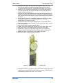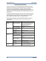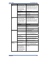
1
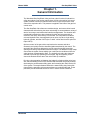
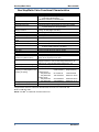
Product Manual 26620 (Revision D, 10/2013) Original Instructions Gas Stop/Ratio Valve This manual is based on manual 26093 revision R. Installation and Operation Manual Read this entire manual and all other publications pertaining to the work to be performed before installing, operating, or servicing this equipment. Practice all plant and safety instructions and precautions. General Precautions Failure to follow instructions can cause personal injury and/or property damage. Revisions This publication may have been revised or updated since this copy was produced. To verify that you have the latest revision, check manual 26311 , Revision Status & Distribution Restrictions of Woodward Technical Publications, on the publications page of the Woodward website: www.woodward.com/publications The latest version of most publications is available on the publications page. If your publication is not there, please contact your customer service representative to get the latest copy. Proper Use Any unauthorized modifications to or use of this equipment outside its specified mechanical, electrical, or other operating limits may cause personal injury and/or property damage, including damage to the equipment. Any such unauthorized modifications: (i) constitute "misuse" and/or "negligence" within the meaning of the product warranty thereby excluding warranty coverage for any resulting damage, and (ii) invalidate product certifications or listings. If the cover of this publication states "Translation of the Original Instructions" please note: The original source of this publication may have been updated since this Translated translation was made. Be sure to check manual 26311 , Revision Status & Publications Distribution Restrictions of Woodward Technical Publications, to verify whether this translation is up to date. Out-of-date translations are marked with . Always compare with the original for technical specifications and for proper and safe installation and operation procedures. Revisions—Changes in this publication since the last revision are indicated by a black line alongside the text. Woodward reserves the right to update any portion of this publication at any time. Information provided by Woodward is believed to be correct and reliable. However, no responsibility is assumed by Woodward unless otherwise expressly undertaken. Manual 26620 Copyright © Woodward 2011–2013 All Rights Reserved Manual 26620 Gas Stop/Ratio Valve Contents WARNINGS AND NOTICES ............................................................................III ELECTROSTATIC DISCHARGE AWARENESS ................................................. IV REGULATORY COMPLIANCE ........................................................................ V CHAPTER 1. GENERAL INFORMATION ........................................................... 1 Gas Stop/Ratio Valve Functional Characteristics ..................................................2 CHAPTER 2. STOP/RATIO VALVE OPERATION ............................................ 23 CHAPTER 3. STANDARD COMPONENT DETAILS .......................................... 24 Triple Coil Electrohydraulic Servo Valve Assembly .............................................24 Trip Relay Valve Assembly...................................................................................24 Hydraulic Filter Assembly .....................................................................................25 LVDT Position Feedback Sensors .......................................................................25 CHAPTER 4. INSTALLATION........................................................................ 26 General .................................................................................................................26 Unpacking .............................................................................................................27 Piping Installation .................................................................................................27 Hydraulic Connections..........................................................................................28 Electrical Connections ..........................................................................................28 Fuel Vent Port .......................................................................................................29 Electronic Settings ................................................................................................29 CHAPTER 5. MAINTENANCE AND HARDWARE REPLACEMENT ..................... 31 Maintenance .........................................................................................................31 Hardware Replacement ........................................................................................31 Troubleshooting Charts ........................................................................................36 CHAPTER 6. SERVICE OPTIONS ................................................................. 38 Product Service Options .......................................................................................38 Woodward Factory Servicing Options ..................................................................39 Returning Equipment for Repair ...........................................................................39 Replacement Parts ...............................................................................................40 Engineering Services............................................................................................40 How to Contact Woodward ...................................................................................41 Technical Assistance ............................................................................................41 REVISION HISTORY .................................................................................... 42 DECLARATIONS ......................................................................................... 43 Woodward i Gas Stop/Ratio Valve Manual 26620 Illustrations and Tables Figure 1-1. Gas Stop/Ratio Valve (typical; 3-inch shown) ......................................3 Figure 1-2. Single Acting Hydraulic Schematic ......................................................4 Figure 1-3a. Electrical Schematic and Wiring Diagram (Dual LVDT).....................5 Figure 1-3b. Electrical Schematic and Wiring Diagram (Triple LVDT, 6” and 8” valves only) ........................................................................................5 Figure 1-4a. LVDT Barrier Wiring Diagram (TIIS requirement, Japan) ..................6 Figure 1-4b. Servo Valve Barrier Wiring Diagram (TIIS requirement, Japan) ........7 Figure 1-5a. Gas Stop/Ratio Valve Outline Drawing (3-inch) .................................9 Figure 1-5b. Gas Stop/Ratio Valve Outline Drawing (3-inch) ...............................10 Figure 1-6a. Gas Stop/Ratio Valve Outline Drawing (4-inch) ...............................11 Figure 1-6b. Gas Stop/Ratio Valve Outline Drawing (4-inch) ...............................12 Figure 1-7a. Gas Stop/Ratio Valve Outline Drawing (6-inch, except SS-260) .....13 Figure 1-7b. Gas Stop/Ratio Valve Outline Drawing (6-inch, except SS-260) .....14 Figure 1-8a. Gas Stop/Ratio Valve Outline Drawing (6-inch, SS-260).................15 Figure 1-8b. Gas Stop/Ratio Valve Outline Drawing (6-inch, SS-260).................16 Figure 1-9a. Gas Stop/Ratio Valve Outline Drawing (6-inch, with 3 LVDTs, SS-260) ............................................................................................17 Figure 1-9b. Gas Stop/Ratio Valve Outline Drawing (6-inch, with 3 LVDTs, SS-260) ............................................................................................18 Figure 1-10a. Gas Stop/Ratio Valve Outline Drawing (8-inch, with 2 LVDTs) .....19 Figure 1-10b. Gas Stop/Ratio Valve Outline Drawing (8-inch, with 2 LVDTs) .....20 Figure 1-11a. Gas Stop/Ratio Valve Outline Drawing (8-inch, with 3 LVDTs) .....21 Figure 1-11b. Gas Stop/Ratio Valve Outline Drawing (8-inch, with 3 LVDTs) .....22 Figure 4-1. Stop/Ratio Valve Block Diagram ........................................................29 Figure 4-2. Structures for PID Control ..................................................................30 Figure 5-1. Stroke Measurement Attachment Bar ................................................35 Table 3-1. Recommended Control Gain Values for Different Control Types .......30 ii Woodward Manual 26620 Gas Stop/Ratio Valve Warnings and Notices Important Definitions This is the safety alert symbol. It is used to alert you to potential personal injury hazards. Obey all safety messages that follow this symbol to avoid possible injury or death. DANGER—Indicates a hazardous situation which, if not avoided, will result in death or serious injury. WARNING—Indicates a hazardous situation which, if not avoided, could result in death or serious injury. CAUTION—Indicates a hazardous situation which, if not avoided, could result in minor or moderate injury. NOTICE—Indicates a hazard that could result in property damage only (including damage to the control). IMPORTANT—Designates an operating tip or maintenance suggestion. Overspeed / Overtemperature / Overpressure Personal Protective Equipment The engine, turbine, or other type of prime mover should be equipped with an overspeed shutdown device to protect against runaway or damage to the prime mover with possible personal injury, loss of life, or property damage. The overspeed shutdown device must be totally independent of the prime mover control system. An overtemperature or overpressure shutdown device may also be needed for safety, as appropriate. The products described in this publication may present risks that could lead to personal injury, loss of life, or property damage. Always wear the appropriate personal protective equipment (PPE) for the job at hand. Equipment that should be considered includes but is not limited to: Eye Protection Hearing Protection Hard Hat Gloves Safety Boots Respirator Always read the proper Material Safety Data Sheet (MSDS) for any working fluid(s) and comply with recommended safety equipment. Start-up Automotive Applications Woodward Be prepared to make an emergency shutdown when starting the engine, turbine, or other type of prime mover, to protect against runaway or overspeed with possible personal injury, loss of life, or property damage. On- and off-highway Mobile Applications: Unless Woodward's control functions as the supervisory control, customer should install a system totally independent of the prime mover control system that monitors for supervisory control of engine (and takes appropriate action if supervisory control is lost) to protect against loss of engine control with possible personal injury, loss of life, or property damage. iii Gas Stop/Ratio Valve Manual 26620 To prevent damage to a control system that uses an alternator or battery-charging device, make sure the charging device is turned off before disconnecting the battery from the system. Battery Charging Device Electrostatic Discharge Awareness Electrostatic Precautions Electronic controls contain static-sensitive parts. Observe the following precautions to prevent damage to these parts: Discharge body static before handling the control (with power to the control turned off, contact a grounded surface and maintain contact while handling the control). Avoid all plastic, vinyl, and Styrofoam (except antistatic versions) around printed circuit boards. Do not touch the components or conductors on a printed circuit board with your hands or with conductive devices. To prevent damage to electronic components caused by improper handling, read and observe the precautions in Woodward manual 82715, Guide for Handling and Protection of Electronic Controls, Printed Circuit Boards, and Modules. Follow these precautions when working with or near the control. 1. Avoid the build-up of static electricity on your body by not wearing clothing made of synthetic materials. Wear cotton or cotton-blend materials as much as possible because these do not store static electric charges as much as synthetics. 2. Do not remove the printed circuit board (PCB) from the control cabinet unless absolutely necessary. If you must remove the PCB from the control cabinet, follow these precautions: Do not touch any part of the PCB except the edges. Do not touch the electrical conductors, the connectors, or the components with conductive devices or with your hands. When replacing a PCB, keep the new PCB in the plastic antistatic protective bag it comes in until you are ready to install it. Immediately after removing the old PCB from the control cabinet, place it in the antistatic protective bag. iv Woodward Manual 26620 Gas Stop/Ratio Valve Regulatory Compliance European Compliance for CE Marking: These listings are limited only to those units bearing the CE Marking. EMC Directive: Declared to 2004/108/EC COUNCIL DIRECTIVE of 15 December 2004 on the approximation of the laws of the Member States relating to electromagnetic compatibility and all applicable amendments. 2004/108/EC is met by evaluation of the physical nature to the EMC protection requirement. Electromagnetically passive or “benign” devices are excluded from the scope of the Directive 2004/108/EC, however they also meet the protection requirement and intent of the directive. Pressure Equipment Directive: (Fisher Valve) Certified to Pressure Equipment Directive 97/23/EC of 29 May 1997 on the approximation of the laws of the Member State concerning pressure equipment, Category III, Bureau Veritas CE-0041-PED-H-FVD-001-11-USA, Module H. Fisher Controls International, LLC Declaration of Conformity is provided with each Gas Stop/Ratio Valve ATEX – Potentially Explosive Atmospheres Directive: Declared to 94/9/EC COUNCIL DIRECTIVE of 23 March 1994 on the approximation of the laws of the Member States concerning equipment and protective systems intended for use in potentiallyexplosive atmospheres. Zone 2, Category 3, Group II G, Ex nA IIC T3X Gc, IP54 See below for special conditions for safe use. Valves with Intrinsically Safe Components— ATEX – Declared to 94/9/EC COUNCIL DIRECTIVE of 23 March Potentially 1994 on the approximation of the laws of the Member States Explosive concerning equipment and protective systems intended for Atmospheres use in potentiallyexplosive atmospheres. Directive: Zone 2, Category 3, Group II G, Ex nA IIC T3X Gc, IP54 Special Conditions for Safe Use: The LVDT and servo valve must be wired using barrier wiring drawings shown in Figure 1-4. Servo valve must not be replaced with one that has previously been installed in ‘nA’ applications. Other European Compliance: Compliance with the following European Directives or standards does not qualify this product for application of the CE Marking: Machinery Directive: Compliant as partly completed machinery with Directive 2006/42/EC of the European Parliament and the Council of 17 May 2006 on machinery. Pressure Compliant as “SEP” per Article 3.3 to Pressure Equipment Equipment Directive 97/23/EC of 29 May 1997 on the approximation of Directive: the laws of the Member States concerning pressure (applies to equipment. actuator portion of valve assembly only) Woodward v Gas Stop/Ratio Valve ATEX: Manual 26620 Exempt from the non-electrical portion of the ATEX Directive 94/9/EC due to no potential ignition sources per EN 13463-1. Other International Compliance TIIS: Applicable to the servo valve and LVDT. Where customer has requested TIIS compliance, the servo valve and LVDT are TIIS-marked and must be installed with barriers as shown in the Installation chapter. GOST R: Certified for use in explosive atmospheres within the Russian Federation per GOST R certificate POCC US. ГБ06.B01025 as ExnAIIT3 X. North American Compliance: Suitability for use in North American Hazardous Locations is the result of compliance of the individual components: LVDT: CSA Certified for Class I, Divisions 1 and 2, Groups A, B, C, D, T4,for use in the United States and Canada per CSA 151336-1090811. OR LVDT: Servo Valve: ETL Certified for Class I, Division 2, Groups A, B, C, D, T3, per ETL J98036083-003, For use in United States and Canada. Certified for Class I, Division 2, Groups A, B, C, D for the United States per FM 4B9A6.AX. CSA Certified for Class I, Division 2, Groups A, B, C, D for use in Canada per CSA 1072373. Junction Box: UL Certified for Class I, Zone 1, AEx e II, Ex e II, T6 for use in North America per UL E203312. Special Conditions for Safe Use—All Valves Wiring must be in accordance with North American Class I, Division 2 or European Zone 2, Category 3 wiring methods as applicable, except for valves requiring intrinsically safe wiring as stated above. Field Wiring must be suitable for at least 100 °C. The wiring junction box provides earth ground terminals if needed for a separate earth ground to meet wiring requirements. T3 reflects conditions without process fluid. The surface temperature of this valve approaches the maximum temperature of the applied process media. It is the responsibility of the user to ensure that the external environment contains no hazardous gases capable of ignition in the range of the process media temperatures. Compliance with the Machinery Directive 2006/42/EC noise measurement and mitigation requirements is the responsibility of the manufacturer of the machinery into which this product is incorporated. The risk of electrostatic discharge is reduced by permanent installation of the valve, proper connection to the protective earth (PE) terminals, and care when cleaning. The valve should not be cleaned unless the area is known to be non-hazardous. vi Woodward Manual 26620 Gas Stop/Ratio Valve EXPLOSION HAZARD—Do not connect or disconnect while circuit is live unless area is known to be non-hazardous. Substitution of components may impair suitability for Class I, Division 2 or Zone 2. RISQUE D’EXPLOSION—Ne pas raccorder ni débrancher tant que l’installation est sous tension, sauf en cas l’ambiance est décidément non dangereuse. La substitution de composants peut rendre ce matériel inacceptable pour les emplacements de Classe I, Division 2 ou Zone 2. Woodward vii Gas Stop/Ratio Valve viii Manual 26620 Woodward Manual 26620 Gas Stop/Ratio Valve Chapter 1. General Information The Woodward Gas Stop/Ratio Valve performs a dual function for industrial or utility gas turbines. One function rapidly shuts off fuel to the turbine fuel control system. Another function provides accurate control of gas fuel pressure at the outlet of the stop/ratio valve. This pressure is applied to the inlets of the gas fuel control valve. The Gas Stop/Ratio Valve features a modular design, and meets critical control characteristics while allowing the same valve design to accommodate a variety of stroke, force output, and mechanical interface arrangements. The electrical and mechanical interfaces have been designed for quick and easy assembly or removal of the valve, at the factory or in the field. The components include an on-board hydraulic filter, electrohydraulic servo valve, trip valve, single-acting hydraulic cylinder, and dual LVDTs (the 6” and 8” valves also have the option for triple LVDTs). Optimum control of the gas turbine requires that the actuator and valve accurately and quickly track the demand signals transmitted by the control. The stop/ratio valve has been designed to provide output forces that exceed the opening and closing requirements with some margin. The additional margin helps ensure that the system moves rapidly even under service conditions where the valve has been contaminated or worn. The hydraulic trip relay valve has been selected to provide high operating force margins, high flow capacity, and to ensure the desired closure rate of the valve under trip conditions. By using a long actuation rod between the hydraulic cylinder and the valve lever arm, the side-loading forces on the actuator shaft and seals are greatly reduced, decreasing the wear between sliding parts, and increasing the useful service life of the system. The ample distance between the wetted heavy-duty linear slide rings within the stop/ratio valve accommodates any remaining side load. These provisions provide extended service life even in severe service conditions. Woodward 1 Gas Stop/Ratio Valve Manual 26620 Gas Stop/Ratio Valve Functional Characteristics Functional Requirement Valve Type Position Accuracy Position Repeatability Hydraulic Fluid Type Maximum Operating Hydraulic Supply Pressure Proof Test Fluid Pressure Level Minimum Burst Fluid Pressure Fluid Filtration Required Hydraulic Fluid Contamination Level Hydraulic Fluid Temperature Actuator Ambient Temperature Vibration Test Level Gas Stop/Ratio Valve Fisher Type Vee-Ball® Design V300 or V300 Series B or V200 Series B Flangeless HD Metal, TCM-Ultra, or SS-260 seals ±1% full scale (over ±25 °F/±14 °C deviation from calibration) ±0.5% of point over the range of 10 to 100% Petroleum Based hydraulic fluids as well as fire resistant hydraulic fluids such as Fyrquel EHC 1200 to 1700 psig (8274 to 11 722 kPa) (design at 1600 psig/11 032 kPa) 2550 psig (20 685 kPa) minimum per SAE J214 (Prod Test) 4250 psig (34 475 kPa) minimum per SAE J214 10–15 µm at 75 Beta Per ISO 4406 code 18/16/13 max, code 16/14/11 preferred +80 to +170 °F (+27 to +77 °C) –20 to +180 °F (–29 to +82 °C) Random 0.01500 gr²/Hz from 10 to 40 Hz ramping down to 0.00015 gr²/Hz at 500 Hz (1.04 Grms) Shock Limited to 30 g by servo valve Trip Time Less than 0.200 seconds (100–0% stroke) Open Slew Time 5 to 95% in 0.500 ±0.15 seconds Close Slew Time 95 to 5% in 0.500 ± 0.15 seconds Trip Pressure Pick up 24 ±6 psid (165 ±41 kPa) (relative to hydraulic return) Drop out 22 ±6 psid (152 ±41 kPa) Hydraulic Fluid Connections Trip Relay Pressure–1.062-12 UNF straight thread port (–12) Supply Pressure–0.750-16 UNF straight thread port (–8) Return Port–1.312-20 UNF straight thread port (–16) Servo Input Current Rating –7.2 to +8.8 mA (null bias 0.8 ±0.32 mA) Paint Two part Epoxy Actuation Forces 3, 4, & 6” valves 6 & 8” valves 1 2 (opening at 1200 psig/8274 kPa) (small actuator ) (large actuator ) Opening Force (closing via spring) Fully Extended 811 lb/3607 N 1200 lb/5338 N Fully Retracted 1581 lb/7032 N 3085 lb/13 722 N Closing Force Fully Extended 2075 lb/9230 N 4690 lb/20 861 N Fully Retracted 1305 lb/5805 N 2805 lb/12 477 N Design Availability Objective Better than 99.5% over an 8760 hour period Sound Level Per Fisher-Rosemount Catalog 12 1 Small actuator used on 3”, 4”, and 6” valves with HD Metal or TCM-Ultra seals 2 Large actuator used on 6” valves with SS-260 seals, as well as on 8” valves with HD Metal or TCM-Ultra seals ® NOTE—Vee-Ball is a trademark of Fisher-Rosemount. 2 Woodward Manual 26620 Gas Stop/Ratio Valve Figure 1-1. Gas Stop/Ratio Valve (typical; 3-inch shown) Woodward 3 Gas Stop/Ratio Valve Manual 26620 Figure 1-2. Single Acting Hydraulic Schematic 4 Woodward Manual 26620 Gas Stop/Ratio Valve Figure 1-3a. Electrical Schematic and Wiring Diagram (Dual LVDT) Figure 1-3b. Electrical Schematic and Wiring Diagram (Triple LVDT, 6” and 8” valves only) Woodward 5 Gas Stop/Ratio Valve Manual 26620 Figure 1-4a. LVDT Barrier Wiring Diagram (TIIS requirement, Japan) [This figure applies to TIIS requirement for Japan only.] 6 Woodward Manual 26620 Gas Stop/Ratio Valve Figure 1-4b. Servo Valve Barrier Wiring Diagram (TIIS requirement, Japan) [This figure applies to TIIS requirement for Japan only.] Woodward 7 Gas Stop/Ratio Valve Manual 26620 Notes for Figures 1-5 through 1-11 1. These general reference outline drawings apply to various Woodward Gas Fuel Stop/Ratio valves. Consult Woodward for the latest outline drawing for your particular stop/ratio valve. 2. Installation Orientation Pipe supported only Orientation vertical approximately as shown See elsewhere in this manual for other installation recommendations 3. Approximate Weight 3” Valve—255 lbs/116 kg 4” Valve—280 lbs/127 kg, 6” Valve (except SS-260)—332 lbs/151 kg 6” Valve (SS-260)—447 lbs/203 kg 8” Valve—540 lbs/245 kg 4. Service Manual Replacement Parts Servo Valve—consult Woodward for part number O-rings for servo valve—consult Woodward for part number Filter element—consult Woodward for part number Manual—consult Woodward for part number LVDT—consult Woodward for part number Trip relay valve—consult Woodward for part number Seal kit for trip relay valve—consult Woodward for part number 5. Description of Stop/Ratio Valve Process fluid natural gas Temperature range natural gas 50 to 300 °F/10 to 149 °C (unheated fuel) natural gas 50 to 450 °F/10 to 232 °C (heated fuel) ambient –20 to +180 °F/–29 to +82 °C External leakage (2 cm³/min maximum to overboard drain) 6. Actuation Cylinder bore 7. Servo Valve Flow rating 1 Small Actuator : 1.750 inch diameter (44.45 mm) Large Actuator2: 2.500 inch diameter (63.50 mm) Stroke 3.500 inch (88.90 mm) Static seals Elastomer per US MIL-R-83248 (Viton) Operating fluid Petroleum-based hydraulic fluid as well as fire resistant hydraulic fluids such as Fyrquel EHC Rated hydraulic pressure 1600 psig/11 032 kPa Operating hydraulic pressure 1200 to 1700 psig/8274 to 11 722 kPa Ambient temperature –20 to +180 °F/–29 to +82 °C Hydraulic fluid temperature 80 to 170 °F/27 to 77 °C Electrical input rating Null bias Electrical connection 1 Small Actuator : 5.0 US gal/min (18.9 L/min) at 1000 psid (6895 kPa) valve drop, 4-way 2 Large Actuator : 10.0 US gal/min (37.8 L/min) at 1000 psid (6895 kPa) valve drop, 4-way ±8 mA (sum of three coils) 10% of rated flow to close stop/ratio valve (= 10 ± 4% rated current at hydraulic null) 0.375 O.D. tube fitting. 0.562-18 UNF-2A thread per MS 33656-6 1 Small actuator used on 3”, 4”, and 6” valves with HD Metal or TCM-Ultra seals Large actuator used on 6” valves with SS-260 seals, as well as on 8” valves with HD Metal or TCM-Ultra seals 2 These general reference outline drawings apply to various Woodward Gas Fuel Stop/Ratio valves. Consult Woodward for the latest outline drawing for your particular stop/ratio valve. 8 Woodward Manual 26620 Gas Stop/Ratio Valve Figure 1-5a. Gas Stop/Ratio Valve Outline Drawing (3-inch) Woodward 9 Gas Stop/Ratio Valve Manual 26620 Figure 1-5b. Gas Stop/Ratio Valve Outline Drawing (3-inch) 10 Woodward Manual 26620 Gas Stop/Ratio Valve Figure 1-6a. Gas Stop/Ratio Valve Outline Drawing (4-inch) Woodward 11 Gas Stop/Ratio Valve Manual 26620 Figure 1-6b. Gas Stop/Ratio Valve Outline Drawing (4-inch) 12 Woodward Manual 26620 Gas Stop/Ratio Valve Figure 1-7a. Gas Stop/Ratio Valve Outline Drawing (6-inch, except SS-260) Woodward 13 Gas Stop/Ratio Valve Manual 26620 Figure 1-7b. Gas Stop/Ratio Valve Outline Drawing (6-inch, except SS-260) 14 Woodward Manual 26620 Gas Stop/Ratio Valve Figure 1-8a. Gas Stop/Ratio Valve Outline Drawing (6-inch, SS-260) Woodward 15 Gas Stop/Ratio Valve Manual 26620 Figure 1-8b. Gas Stop/Ratio Valve Outline Drawing (6-inch, SS-260) 16 Woodward Manual 26620 Gas Stop/Ratio Valve Figure 1-9a. Gas Stop/Ratio Valve Outline Drawing (6-inch, with 3 LVDTs, SS-260) Woodward 17 Gas Stop/Ratio Valve Manual 26620 Figure 1-9b. Gas Stop/Ratio Valve Outline Drawing (6-inch, with 3 LVDTs, SS-260) 18 Woodward Manual 26620 Gas Stop/Ratio Valve Figure 1-10a. Gas Stop/Ratio Valve Outline Drawing (8-inch, with 2 LVDTs) Woodward 19 Gas Stop/Ratio Valve Manual 26620 Figure 1-10b. Gas Stop/Ratio Valve Outline Drawing (8-inch, with 2 LVDTs) 20 Woodward Manual 26620 Gas Stop/Ratio Valve Figure 1-11a. Gas Stop/Ratio Valve Outline Drawing (8-inch, with 3 LVDTs) Woodward 21 Gas Stop/Ratio Valve Manual 26620 Figure 1-11b. Gas Stop/Ratio Valve Outline Drawing (8-inch, with 3 LVDTs) 22 Woodward Manual 26620 Gas Stop/Ratio Valve Chapter 2. Stop/Ratio Valve Operation The Gas Stop/Ratio Valve actuator is controlled by an electronic servo-control system (not included), which compares the demanded and actual valve positions. The control system modulates the input current signal to the electrohydraulic servo valve to minimize the positioning system error. See Figure 1-2 for a functional schematic of the single acting actuator. Hydraulic oil enters the actuator via a removable element filter with integral high P indicator and is directed to a four way, electrohydraulic servo valve used in a three-way configuration. The PC1 control pressure output from the servo valve is directed to the top of the hydraulic piston. When the force exerted by the hydraulic pressure exceeds the force of the opposing loading springs, the output piston extends, rotating the valve in the opening direction. A trip relay valve assembly is interposed between the electrohydraulic servo control valve and the servo output stage. Loss or reduction of the externally supplied trip signal pressure causes the trip relay valve to shift position. This connects the upper cavity of the actuator piston to the hydraulic drain. The force supplied by the return springs pushes the actuation rod up, rotating the valve to the closed position. Two redundant LVDT position feedback transducers are also mounted within each actuator. An optional third LVDT is available on the 6” and 8” stop/ratio actuators only. The LVDT sensor cores and support rods are connected to the main actuator output rod by a coupling arrangement guided on a bushing. This guide bushing maintains LVDT alignment to minimize core damage due to sliding wear and the associated loss of sensing accuracy. Woodward 23 Gas Stop/Ratio Valve Manual 26620 Chapter 3. Standard Component Details Triple Coil Electrohydraulic Servo Valve Assembly The stop/ratio valve actuator utilizes a two stage hydraulic servo valve to modulate the position of the output shaft and thereby control the stop ratio valve. The first stage torque motor utilizes a triple wound coil, which controls the position of the first and second stage valves in proportion to the total electrical current applied to the three coils. If the control system requires a rapid movement of the valve to increase fuel pressure to the control valves, the total current is increased well above the null current. In such a condition, supply oil is admitted to the cavity above the actuator piston. The flow rate delivered to the upper piston cavity is proportional to the total current applied to the three coils. Thus, the actuator stroke velocity and the valve opening are also proportional to the current (above null) supplied to the torque motor above the null point. If the control system requires a rapid movement to reduce fuel pressure downstream of the stop/ratio valve, the total current is reduced well below the null current. In such a condition, the actuator piston cavity is connected to the hydraulic drain circuit. The flow rate returning from the upper piston cavity of the valve is proportional to the magnitude of the total current below the null value. The flow rate and closing velocity of the valve are in this case proportional to the total current below the null point. Near the null current, the servo valve essentially isolates the upper piston cavity from the hydraulic supply and drain, and the upper piston pressure and spring load are balanced to maintain a constant position. The control system, which regulates the amount of current delivered to the coils, modulates the current supplied to the coil to obtain proper closed loop operation of the system. Trip Relay Valve Assembly The stop/ratio valve utilizes a three-way, two position, hydraulically operated valve to switch the position of the gas stop/ratio valve. When the trip circuit pressure increases above 24 ±6 psid (165 ±41 kPa) relative to hydraulic drain pressure, the three-way relay valve shifts position. The servo valve control port is then connected to the actuator upper piston cavity, and this interconnecting route is isolated from the drain passage. Actuation pressure is routed to the upper piston cavity of the valve, allowing the gas stop/ratio actuator to function. As the trip circuit supply pressure reduces below 22 ±6 psid (152 ±41 kPa) relative to hydraulic drain pressure, the three-way relay valve shifts position such that the upper piston cavity is connected to the hydraulic drain circuit, and isolated from the hydraulic supply. As the pressure falls within the upper piston cavity, the return spring rapidly returns the actuator piston to the upward position, closing the stop ratio valve and shutting off fuel to the engine. 24 Woodward Manual 26620 Gas Stop/Ratio Valve Hydraulic Filter Assembly The stop/ratio actuator is supplied with an integrated, high capacity filter. This broad range filter protects the internal hydraulic control components from large oil-borne contaminants that might cause the hydraulic components to stick or operate erratically. The filter is supplied with a visual indicator which indicates when the pressure differential exceeds the recommended value, indicating that replacement of the element is necessary. LVDT Position Feedback Sensors The stop/ratio actuator uses dual LVDTs for position feedback. An optional third LVDT is available on the 6” and 8” stop/ratio actuators only. The LVDTs are factory set to give 0.7 ±0.1 Vrms feedback at minimum position and 3.5 ±0.5 Vrms feedback at maximum position. The actual voltage values for each LVDT are recorded on a label placed inside the actuator electrical box, for reference during field calibration. Woodward 25 Gas Stop/Ratio Valve Manual 26620 Chapter 4. Installation General See the outline drawings (Figures 1-5 through 1-11) for: Overall dimensions Process piping flange locations Hydraulic fitting sizes Electrical connections Lift points and center of gravity Weight of the valve The design of the Vee-Ball® valve requires that the rotary drive shaft be mounted horizontally. Additionally, a vertical actuator position is generally preferred to conserve floor space as well as ease of making electrical, fuel, and hydraulic connections and changing the hydraulic filter element. The stop/ratio valve is designed for support by the piping flanges alone. Additional supports are neither needed nor recommended. The standard stop/ratio valve is supplied with a left-hand orientation as shown in the outline drawing. The valve can be configured with a right-hand orientation; however, this request must be on the purchase order at the time the order is placed for this change to take place. External fire protection is not provided in the scope of this product. It is the responsibility of the user to satisfy any applicable requirements for their system. Due to typical noise levels in turbine environments, hearing protection should be worn when working on or around the valve. The surface of this product can become hot enough or cold enough to be a hazard. Use protective gear for product handling in these circumstances. Temperature ratings are included in the specification section of this manual. Do not lift or handle the valve by any conduit. Lift or handle the valve only by using the eyebolts. The surface temperature of this valve approaches the maximum temperature of the applied process media. It is the responsibility of the user to ensure that the external environment contains no hazardous gases capable of ignition in the range of the process media temperatures. 26 Woodward Manual 26620 Gas Stop/Ratio Valve Unpacking The valve is shipped in an airtight bag with desiccant to ensure a non-corrosive environment. We recommend that the valve be kept in its shipping container until installation. If the valve is to be stored for extended periods of time, encase the valve in an airtight container with desiccant. Piping Installation Refer to ANSI B16.5 for details of flange, gasket, and bolt types and dimensions. Verify that the process piping flange-to-flange-face dimensions meet the requirements of the outline drawings (Figures 1-5 through 1-11) within standard piping tolerances. The valve should mount between the piping interfaces such that the flange bolts can be installed with only manual pressure applied to align the flanges. Mechanical devices such as hydraulic or mechanical jacks, pulleys, chain-falls, or similar should never be used to force the piping system to align with the valve flanges. The stop/ratio valve is designed for support by the piping flanges alone; additional supports are neither needed nor recommended. Grade 5 (metric class 8.8) bolts or studs should be used to install the valve into the process piping. The length and diameter for Class 300 flanges shall conform to the following table according to the valve flange size. Nominal Pipe Size 1 inch/ 25 mm 2 inch/ 51 mm 3 inch/ 76 mm 4 inch/ 102 mm 6 inch/ 152 mm 8 inch/ 203 mm Number of Bolts 4 8 8 8 8 12 Diameter of Bolts 5/8 inch/ 16 mm 3/4 inch/ 19 mm 3/4 inch/ 19 mm 3/4 inch/ 19 mm 3/4 inch/ 19 mm 7/8 inch/ 22 mm Stud Length 3.00 inch/ 76.2 mm 3.50 inch/ 88.9 mm 4.25 inch/ 108.0 mm 4.50 inch/ 114.3 mm 4.75 inch/ 120.6 mm 5.50 inch/ 139.7 mm Machine Bolt Length 2.50 inch/ 63.5 mm 3.00 inch/ 76.2 mm 3.50 inch/ 88.9 mm 3.75 inch/ 95.2 mm 4.25 inch/ 108.0 mm 4.75 inch/ 120.6 mm Flange gasket materials should conform to ANSI B16.20. The user should select a gasket material which will withstand the expected bolt loading without injurious crushing, and which is suitable for the service conditions. When installing the valve into the process piping, it is important to properly torque the stud/bolts in the appropriate sequence in order to keep the flanges of the mating hardware parallel to each other. A two-step torque method is recommended. Once the studs/bolts are hand tightened, torque the studs/bolts in a crossing pattern to half the torque value listed in the following table. Once all studs/bolts have been torqued to half the appropriate value, repeat the pattern until the rated torque value is obtained. Bolt Size 5/8 inch/16 mm 3/4 inch/19 mm 7/8 inch/22 mm Woodward Torque 150–155 lb-ft/203–210 Nm 250–260 lb-ft/339–353 Nm 375–390 lb-ft/508–529 Nm 27 Gas Stop/Ratio Valve Manual 26620 Hydraulic Connections There are three hydraulic connections that must be made to each valve: supply, return, and trip oil. The connections to the valve are straight-thread O-ring style ports per SAE J514. The tubing up to the valve must be constructed to eliminate any transfer of vibration or other forces into the valve. Make provisions for proper filtration of the hydraulic fluid that will supply the actuator. The system filtration should be designed to assure a supply of hydraulic oil with a maximum ISO 4406 contamination level of 18/16/13 and a preferred level of 16/14/11. The filter element included with the actuator is not intended to provide adequate filtration over the entire life of the actuator. The hydraulic supply to the actuator is to be 0.500 inch (12.70 mm) tubing capable of supplying 10 US gallons/min (18 L/min) at 1200–1700 psig (8274–11 722 kPa). The hydraulic drain should be 1.00 inch (25.4 mm) tubing and must not restrict the flow of fluid from the valve. The drain pressure must not exceed 30 psig (207 kPa) under any condition. The trip relay valve supply should be 0.750 inch (19.05 mm) tubing. The Trip Relay Pressure should be above 40 psig (276 kPa) to enable the valve to function. Electrical Connections EXPLOSION HAZARD—Do not connect or disconnect while circuit is live unless area is known to be non-hazardous. Due to the hazardous location listings associated with this valve, proper wire type and wiring practices are critical to operation. Protective earth (PE) ground must be connected on the junction box per the installation drawing to reduce the risk of electrostatic discharge in an explosive atmosphere. Do not connect any cable grounds to “instrument ground”, “control ground”, or any non-earth ground system. Make all required electrical connections based on the wiring diagram (Figures 1-3 & 1-4). The use of cable with individually-shielded twisted pairs is recommended. All signal lines should be shielded to prevent picking up stray signals from nearby equipment. Installations with severe electromagnetic interference (EMI) may require shielded cable run in conduit, double-shielded wire, or other precautions. Connect the shields at the control system side or as indicated by the control system wiring practices, but never at both ends of the shield such that a ground loop is created. Wires exposed beyond the shield must be less than 2 inches (51 mm). The wiring should provide signal attenuation to greater than 60 dB. 28 Woodward Manual 26620 Gas Stop/Ratio Valve Servo Valve Electrical Connection Servo valve cable must consist of three individually shielded twisted pairs. Each pair should be connected to one coil of the servo valve as indicated in Figures 1-3 and 1-4 (Wiring Diagram). For valves with TIIS requirements (in Japan), the servo valve wiring must be installed with barriers, as shown in Figure 1-4b as required for use with the intrinsically safe method of protection. LVDT Electrical Connection The LVDT cable must consist of two individually shielded twisted pairs for each LVDT. A separate pair should be used for each of the excitation voltages to each LVDT, and a separate pair used for each of the feedback voltages from each LVDT. For valves with TIIS requirements (in Japan), the LVDT wiring must be installed with barriers, as shown in Figure 1-4a as required for use with the intrinsically safe method of protection. Fuel Vent Port The fuel vent port must be vented to a safe location. In normal operation, this vent should have zero leakage. However, if excessive leakage is detected from this vent port, contact a Woodward representative for assistance. Electronic Settings Dynamic Tuning Parameters It is imperative that the correct dynamic characteristics of this valve be input into the control system to ensure that the operation of the valve/control system is within acceptable limits. Figure 4-1. Stop/Ratio Valve Block Diagram Woodward 29 Gas Stop/Ratio Valve Manual 26620 3.0 in³/sec/mA at 1600 psi supply (small actuator1); 6.0 in²/sec/mA at 1600 psi supply (large actuator1); Ksv is proportional to square root of supply, and constant with position. ZetaSV = 0.7 WnSV = 680 rad/sec (108 Hz); WnSV is proportional to square root of supply 1 1 Ac = 2.4 in² (small actuator ); 4.9 in² (large actuator ) KL = 0.80 Vrms/inch Servo Travel = 3.5 inches TauL = 0.005 seconds (depends on excitation/demodulation) 1 See page 2 for usage of small and large actuators Ksv nominal = Figure 4-2. Structures for PID Control Control Gain Settings Proportional Control Kp=5; Proportional Integral Kp=3; Ki=5; Proportional Integral Derivative Kp=3; Ki=5; Kd=0.01 or Tau Lead = 0.01 Table 3-1. Recommended Control Gain Values for Different Control Types Null Current Adjustment Every valve shipped contains documentation that gives the actual Null Current as measured by Woodward. It is imperative that the control system null current match the as-measured current for each valve in the system. Incorrect null current setting, with proportional control only, will result in position error. Rigging Procedure Inside the electrical enclosure of the valve, there is an adhesive label that contains the appropriate valve position (as a percent of full stroke), the physical stroke (inches), and the corresponding LVDT feedback signals for each LVDT (assuming 7.0 Vrms excitation at 3000 Hz). Once the control system is connected to the valve and control of the valve is established, set the valve command position to 0% of full stroke. Measure the feedback voltage from each LVDT. Adjust the Offset in the feedback loop until the feedback voltage matches the documented values (see the label inside the electrical enclosure) for that position. Adjust the command position to 100% of full stroke. Adjust the Gain of the feedback loop until the LVDT feedback voltage matches the documented values. Set the command position to close the valve. Verify that the valve is closed visually and that the feedback voltage from the LVDT is 0.7 ± 0.1 Vrms. This process may have to be repeated to ensure the feedback voltages at both the 0% and 100% command positions match the documented values. 30 Woodward Manual 26620 Gas Stop/Ratio Valve Chapter 5. Maintenance and Hardware Replacement Maintenance Any cleaning by hand or with water spray must be performed while the area is known to be non-hazardous to prevent an electrostatic discharge in an explosive atmosphere. The Gas Stop/Ratio Valve requires no maintenance or adjustment in preparation for or during normal operation. Woodward recommends routine checks of the DP gauge on the filter assembly to verify that the filter is not partially clogged. If the DP indicator shows red, the filter element needs to be replaced. In the event that any of the standard components of the valve become inoperative, field replacement of certain components is possible. Contact a Woodward representative for assistance. Hardware Replacement To prevent possible serious personal injury, or damage to equipment, be sure all electric power, hydraulic pressure and gas pressure have been removed from the valve and actuator before beginning any maintenance or repairs. EXPLOSION HAZARD—Do not connect or disconnect while circuit is live unless area is known to be non-hazardous. Substitution of components may impair suitability for Class I, Division 2 or Zone 2. External fire protection is not provided in the scope of this product. It is the responsibility of the user to satisfy any applicable requirements for their system. Do not lift or handle the valve by any conduit. Lift or handle the valve only by using the eyebolts. Due to typical noise levels in turbine environments, hearing protection should be worn when working on or around the Gas Stop/Ratio valve. The surface of this product can become hot enough or cold enough to be a hazard. Use protective gear for product handling in these circumstances. Temperature ratings are included in the specification section of this manual. See the outline drawings (Figures 1-5 through 1-11) for the location of items. Woodward 31 Gas Stop/Ratio Valve Manual 26620 Hydraulic Filter Assembly/Cartridge The hydraulic filter is located on the hydraulic manifold, hanging directly under the servo valve. Replacement of Filter Assembly 1. Remove four 0.312-18 UNC socket head cap screws. 2. Remove the filter assembly from manifold block. The filter contains a large amount of hydraulic fluid that may be spilled during filter removal. 3. Remove the two O-rings present in the interface between the filter and the manifold. 4. Obtain a new filter assembly. 5. Place two new O-rings in the new filter assembly. 6. Install filter onto manifold assembly. Be sure to place the filter in the correct orientation. See the outline drawings (Figures 1-5 through 1-11). 7. Install four 0.312-18 cap screws through filter and torque into manifold to 244–256 lb-in (27.6–28.9 Nm). Replacement of Filter Cartridge The filter contains a large amount of hydraulic fluid that may be spilled during filter removal. 1. Using a 1-5/16 inch (~33+ mm) wrench, loosen the bowl from the filter assembly. 2. Remove the filter element by pulling it downward. 3. Obtain a new filter element. 4. Lubricate the O-ring on the ID of the cartridge with hydraulic fluid. 5. Install the cartridge into the assembly by sliding the open end of the cartridge upward onto the nipple. 6. Install the filter bowl. Tighten only by hand. Trip Relay Valve Cartridge The trip relay valve cartridge is located in the hydraulic manifold block. Hydraulic fluid may spill during cartridge removal. 1. Using a 1.5 inch (~38+ mm) wrench, loosen the trip relay valve from the hydraulic manifold. 2. Slowly remove the cartridge from the manifold. 3. Obtain new trip relay valve cartridge and verify part number and revision with existing unit. 4. Verify that all O-rings and backup rings are present on new cartridge. 5. Lubricate O-rings with hydraulic fluid or petroleum jelly. 6. Install cartridge into manifold housing. 7. Torque to 80–90 lb-ft (108–122 Nm). 32 Woodward Manual 26620 Gas Stop/Ratio Valve Servo Valve The servo valve is located on the hydraulic manifold directly above the filter assembly. Refer to the outline drawings (Figures 1-5 through 1-11). There could be a substantial amount of hydraulic fluid upon removal. 1. Remove the cover to the electrical junction box. 2. Disconnect the servo valve wires from the connector blocks, as shown in the wiring diagram (Figure 1-3a or 1-3b). 3. Loosen the conduit fittings from the electrical box and the servo valve. 4. Carefully remove the conduit from the servo valve and pull the wiring out of the conduit. 5. Remove the four #10-32 UNF socket head cap screws holding the servo valve to the manifold. 6. Discard the eight O-rings between the servo valve, the adapter plate, and the manifold. 7. Obtain replacement servo valve and verify part number and revision with existing unit. 8. Place four new O-rings on the adapter plate. 9. Reposition adapter plate onto hydraulic manifold ensuring hydraulic passages and bolt holes are aligned correctly. Be sure that all four O-rings remain in their proper location during assembly on the lower side of the adaptor plate facing the manifold. 10. Remove protective plate from replacement servo valve and verify that O-rings are on all four counter bores of the servo valve. 11. Place the servo valve onto the adapter plate that has been positioned on the hydraulic manifold. Be sure to orient the servo valve to match the original orientation. Be sure that all four O-rings remain in their proper location during assembly. 12. Install four #10-32 UNF socket head cap screws and torque to 32–35 lb-in (3.6–4.0 Nm). 13. Install the servo valve wiring through conduit and into electrical box. 14. Connect conduit to servo valve and torque to 450–550 lb-in (51–62 Nm). 15. Torque conduit to electrical box to 450–550 lb-in (51–62 Nm). 16. Install wires into servo valve connector blocks as shown in the wiring diagram (Figure 1-3a or 1-3b). If it is necessary to cut wires for installation, be sure to retain at least one service loop of wiring. 17. Replace cover onto junction box and tighten screws. LVDT Replacement To prevent possible personal injury, do NOT remove the spring cover (which is spring-loaded to over 1000 lbs/4448 N). The LVDTs are located on the upper mounting plate located on the top of the large spring cylinder and below the hydraulic manifold. Refer to the outline drawings (Figures 1-5 through 1-11). 1. 2. 3. 4. Woodward Remove the cover to the electrical junction box. Disconnect each set of LVDT wires from the connector blocks. Loosen the conduit fittings from the electrical box and from each LVDT. Carefully remove the conduit from the LVDTs and pull the wiring out of the conduit. 33 Gas Stop/Ratio Valve Manual 26620 5. Disconnect the hydraulic drain connection for improved working space. There could be a substantial amount of hydraulic fluid upon removal. 6. Remove the 0.500-20 UNF mounting nut from the defective LVDT only. 7. Remove the two 0.250-20 UNC socket head cap screws holding the LVDT bracket to the upper mounting plate. 8. Carefully remove the LVDT assembly from the valve by lifting vertically upwards. Take care not to damage the good LVDT housing and rod. 9. Remove the four #10-32 UNF screws holding the access cover on the side of the spring cylinder to gain access to the LVDT rods. 10. Remove 0.375-24 UNF jam nut from defective LVDT rod. 11. Remove the defective LVDT rod using the 0.250 inch flats at the top of the threads. The rod will be difficult to unscrew due to the thread-locking feature incorporated into the spring plate. 12. Obtain replacement LVDT and verify part number and revision with existing unit. 13. Install replacement LVDT rod into spring plate, positioning the rod height to approximately match the other LVDT rod height. 14. Install the 0.375-24 UNF jam nut onto the LVDT rod but do not torque nut at this time. 15. Carefully slide replacement LVDT through upper mounting plate and over the LVDT rod. Be very careful not to force the LVDT at any time since this could damage the LVDT rod. 16. Carefully reinstall the good LVDT and bracket assembly through upper mounting plate and over the LVDT rod. Be very careful not to force the LVDT at any time since this could damage the LVDT rod. 17. Install the two 0.250-20 UNC socket head cap screws holding the LVDT bracket to the upper mounting plate and torque to 58–78 lb-in (6.6–8.8 Nm). 18. Install replacement LVDT into mounting bracket and torque 0.500-20 UNF mounting nut to 400–500 lb-in (45–56 Nm). 19. Mark the LVDT wire sets so that each set of LVDT wires is distinct. Once the LVDT wires are installed into the electrical box, it will be difficult to distinguish the sets if they are not marked. 20. Install wiring through conduit and into electrical box. 21. Connect conduit to LVDTs and torque to 450–550 lb-in (51–62 Nm). 22. Torque conduit to electrical box to 450–550 lb-in (51–62 Nm). 23. Install wires into LVDT connector blocks as shown in the wiring diagram (Figure 1-3a or 1-3b). If it is necessary to cut wires for installation, be sure to retain at least one service loop of wiring. 24. Reattach the hydraulic drain connection. 25. Once the LVDT is installed, it must then be calibrated as described below. LVDT Calibration 1. Whenever an LVDT is replaced, or whenever its core rod adjustment is disturbed, the LVDT output voltage must be calibrated in the following way. Use care and follow all instructions after removal of the spring access cover. Internal components can potentially crush fingers, and some components are held under significant force. 2. Shut off the hydraulic supply to the stop/ratio actuator. 3. Remove the access cover from the side of the stop/ratio actuator housing by removing the four #10-32 UNF screws and washers, exposing the LVDT core rod adjustment. 34 Woodward Manual 26620 Gas Stop/Ratio Valve 4. Adjust the LVDT rod so that the output of the replaced LVDT is 0.7 ± 0.1 Vrms with the stop/ratio actuator fully retracted (gas valve fully closed). 5. Tighten the 1.375-24 UNF LVDT rod jam nut to 270–320 lb-in (31–36 Nm). 6. Install the stroke measurement attachment bar (Woodward part number 1327-945 provided with the stop/ratio actuator) to the moving plate of the actuator as shown in Figure 5-1. 7. Attach an accurate stroke measurement device (dial indicator or equivalent), capable of measuring 4 inches (100 mm) of stroke, to the stop/ratio actuator body. Position the indicator plunger tip on the measurement bar, as shown in Figure 5-1. 8. Apply hydraulic pressure to the stop/ratio actuator and manually command the actuator to stroke 3.500 ± 0.005 inches (88.90 ± 0.13 mm) by manipulating the electronic controller. 9. Note and record the LVDT output voltages at this 3.5 inch stroke position. 10. Remove the actuator control command, returning the actuator to its rest (gas valve closed) position. 11. Shut off the stop/ratio actuator hydraulic supply. 12. Update the stop/ratio control logic with the new LVDT output voltage value. 13. Remove the cover on the stop/ratio actuator electrical junction box. 14. Replace the original LVDT max output voltage value on the label in the stop/ratio actuator electrical junction box with the newly measured value. 15. Replace the cover on the junction box and tighten the screws. 16. Remove the dial indicator and measurement bar. Figure 5-1. Stroke Measurement Attachment Bar 17. Reinstall the access cover with four #10-32 UNF screws, adjusting the closed indicator mark to align with the position indicator screw slot. Tighten the four cover attaching screws to 30–40 lb-in (3.4–4.5 Nm). Woodward 35 Gas Stop/Ratio Valve Manual 26620 Troubleshooting Charts Faults in the fuel control or governing system are often associated with speed variations of the prime mover, but such speed variations do not always indicate fuel control or governing system faults. Therefore, when improper speed variations occur, check all components including the engine or turbine for proper operation. Refer to applicable electronic control manuals for assistance in isolating the trouble. The following steps describe troubleshooting for the gas fuel stop/ratio valve. Disassembly of the gas fuel stop/ratio valve in the field is not recommended due to the dangerous forces contained in the springs. Under unusual circumstances where disassembly becomes necessary, all work and adjustments should be made by personnel thoroughly trained in the proper procedures. When requesting information or service help from Woodward, it is important to include the part number and serial number of the valve assembly in your communication. Symptom External hydraulic leakage Internal hydraulic leakage External gas fuel leakage Possible Causes Static O-ring seal(s) missing or deteriorated Dynamic O-ring seal missing or deteriorated Servo valve internal O-ring seal(s) missing or deteriorated Servo valve metering edges worn Piston seal missing or deteriorated Piping flange gaskets missing or deteriorated Piping flanges improperly aligned Piping flange bolts improperly torqued Internal gas fuel leakage 36 Packing follower needs adjustment Packing missing or deteriorated Vee-Ball seal missing or deteriorated Remedies Replace O-rings fitted to userserviceable components (filter, servo valve, trip relay valve) as needed. Otherwise, return actuator to Woodward for service. Return actuator to Woodward for service. Replace servo valve. Replace servo valve. Return actuator to Woodward for service. Replace gaskets. Rework piping as needed to achieve alignment requirements detailed in Chapter 4. Rework bolts as needed to achieve torque requirements detailed in Chapter 4. Adjust follower per Fisher manual Form 5290, Type Vee-Ball. Service packing per Fisher manual Form 5290, Type Vee-Ball. Service seal per Fisher manual Form 5290, Type Vee-Ball, and Fisher Errata Sheet Type Vee-Ball SS-260. Woodward Manual 26620 Symptom Valve will not open Gas Stop/Ratio Valve Possible Causes Servo valve command current incorrect. (The sum of the current through the three coils of the servo valve must be greater than the null bias of the servo valve for the gas valve to open.) Servo valve failure Hydraulic supply pressure inadequate Trip relay pressure inadequate Vee-Ball jammed Valve will not close Servo valve command current incorrect. (The sum of the current through the three coils of the servo valve must be less than the null bias of the servo valve for the gas valve to close.) Servo valve failure LVDT failure Springs broken Linkage broken Vee-Ball jammed Valve will not respond smoothly Hydraulic filter clogged Servo valve spool sticking Servo valve internal pilot filter clogged Excessive friction in Vee-Ball assembly Rod-end(s) worn out Piston seal worn out Actuator seals wear out prematurely Hydraulic contamination level is excessive System is oscillating (seal life is proportional to distance traveled). Even small oscillations (on the order of ±1%) at slow frequencies (on the order of 0.1 Hz) cause wear to accumulate rapidly. Woodward Remedies Trace and verify that all wiring is in accordance with the electrical schematic (Figures 1-3a, 1-3b, or 1-4b) and the GE system wiring schematic(s). Pay special attention to the polarity of the wiring to the servo valve and LVDT. Replace servo valve. Supply pressure must be greater than 1200 psig/8274 kPa (1600 psig/11 032 kPa preferred). Trip pressure must be greater than 40 psig (276 kPa). Service Vee-Ball per Fisher manual Form 5290, Type Vee-Ball. Trace and verify that all wiring is in accordance with the electrical schematic (Figures 1-3a, 1-3b, or 1-4b) and the GE system wiring schematic(s). Pay special attention to the polarity of the wiring to the servo valve and LVDT. Replace servo valve. Replace LVDT. Return actuator to Woodward for service. Return actuator to Woodward for service. Service Vee-Ball per Fisher manual Form 5290, Type Vee-Ball. Check the differential pressure indicator on the filter housing. Verify hydraulic contamination levels are within recommendations of Chapter 1. The use of dither may improve performance in contaminated systems. Replace servo valve. Service Vee-Ball per Fisher manual Form 5290, Type Vee-Ball, and Fisher Errata Sheet Type Vee-Ball SS-260. Return actuator to Woodward for service. Return actuator to Woodward for service. Verify hydraulic contamination levels are within recommendations of Chapter 1. The use of excessive dither may reduce life in contaminated systems. Determine and eliminate the root cause of oscillation. 37 Gas Stop/Ratio Valve Manual 26620 Chapter 6. Service Options Product Service Options If you are experiencing problems with the installation, or unsatisfactory performance of a Woodward product, the following options are available: Consult the troubleshooting guide in the manual. Contact the manufacturer or packager of your system. Contact the Woodward Full Service Distributor serving your area. Contact Woodward technical assistance (see “How to Contact Woodward” later in this chapter) and discuss your problem. In many cases, your problem can be resolved over the phone. If not, you can select which course of action to pursue based on the available services listed in this chapter. OEM and Packager Support: Many Woodward controls and control devices are installed into the equipment system and programmed by an Original Equipment Manufacturer (OEM) or Equipment Packager at their factory. In some cases, the programming is password-protected by the OEM or packager, and they are the best source for product service and support. Warranty service for Woodward products shipped with an equipment system should also be handled through the OEM or Packager. Please review your equipment system documentation for details. Woodward Business Partner Support: Woodward works with and supports a global network of independent business partners whose mission is to serve the users of Woodward controls, as described here: A Full Service Distributor has the primary responsibility for sales, service, system integration solutions, technical desk support, and aftermarket marketing of standard Woodward products within a specific geographic area and market segment. An Authorized Independent Service Facility (AISF) provides authorized service that includes repairs, repair parts, and warranty service on Woodward's behalf. Service (not new unit sales) is an AISF's primary mission. A Recognized Engine Retrofitter (RER) is an independent company that does retrofits and upgrades on reciprocating gas engines and dual-fuel conversions, and can provide the full line of Woodward systems and components for the retrofits and overhauls, emission compliance upgrades, long term service contracts, emergency repairs, etc. A Recognized Turbine Retrofitter (RTR) is an independent company that does both steam and gas turbine control retrofits and upgrades globally, and can provide the full line of Woodward systems and components for the retrofits and overhauls, long term service contracts, emergency repairs, etc. You can locate your nearest Woodward distributor, AISF, RER, or RTR on our website at: www.woodward.com/directory 38 Woodward Manual 26620 Gas Stop/Ratio Valve Woodward Factory Servicing Options The following factory options for servicing Woodward products are available through your local Full-Service Distributor or the OEM or Packager of the equipment system, based on the standard Woodward Product and Service Warranty (5-01-1205) that is in effect at the time the product is originally shipped from Woodward or a service is performed: Replacement/Exchange (24-hour service) Flat Rate Repair Flat Rate Remanufacture Replacement/Exchange: Replacement/Exchange is a premium program designed for the user who is in need of immediate service. It allows you to request and receive a like-new replacement unit in minimum time (usually within 24 hours of the request), providing a suitable unit is available at the time of the request, thereby minimizing costly downtime. This is a flat-rate program and includes the full standard Woodward product warranty (Woodward Product and Service Warranty 5-01-1205). This option allows you to call your Full-Service Distributor in the event of an unexpected outage, or in advance of a scheduled outage, to request a replacement control unit. If the unit is available at the time of the call, it can usually be shipped out within 24 hours. You replace your field control unit with the like-new replacement and return the field unit to the Full-Service Distributor. Charges for the Replacement/Exchange service are based on a flat rate plus shipping expenses. You are invoiced the flat rate replacement/exchange charge plus a core charge at the time the replacement unit is shipped. If the core (field unit) is returned within 60 days, a credit for the core charge will be issued. Flat Rate Repair: Flat Rate Repair is available for the majority of standard products in the field. This program offers you repair service for your products with the advantage of knowing in advance what the cost will be. All repair work carries the standard Woodward service warranty (Woodward Product and Service Warranty 5-01-1205) on replaced parts and labor. Flat Rate Remanufacture: Flat Rate Remanufacture is very similar to the Flat Rate Repair option with the exception that the unit will be returned to you in “likenew” condition and carry with it the full standard Woodward product warranty (Woodward Product and Service Warranty 5-01-1205). This option is applicable to mechanical products only. Returning Equipment for Repair If a control (or any part of an electronic control) is to be returned for repair, please contact your Full-Service Distributor in advance to obtain Return Authorization and shipping instructions. When shipping the item(s), attach a tag with the following information: return authorization number; name and location where the control is installed; name and phone number of contact person; complete Woodward part number(s) and serial number(s); description of the problem; instructions describing the desired type of repair. Woodward 39 Gas Stop/Ratio Valve Manual 26620 Packing a Control Use the following materials when returning a complete control: protective caps on any connectors; antistatic protective bags on all electronic modules; packing materials that will not damage the surface of the unit; at least 100 mm (4 inches) of tightly packed, industry-approved packing material; a packing carton with double walls; a strong tape around the outside of the carton for increased strength. To prevent damage to electronic components caused by improper handling, read and observe the precautions in Woodward manual 82715, Guide for Handling and Protection of Electronic Controls, Printed Circuit Boards, and Modules. Replacement Parts When ordering replacement parts for controls, include the following information: the part number(s) (XXXX-XXXX) that is on the enclosure nameplate; the unit serial number, which is also on the nameplate. Engineering Services Woodward offers various Engineering Services for our products. For these services, you can contact us by telephone, by email, or through the Woodward website. Technical Support Product Training Field Service Technical Support is available from your equipment system supplier, your local FullService Distributor, or from many of Woodward’s worldwide locations, depending upon the product and application. This service can assist you with technical questions or problem solving during the normal business hours of the Woodward location you contact. Emergency assistance is also available during non-business hours by phoning Woodward and stating the urgency of your problem. Product Training is available as standard classes at many of our worldwide locations. We also offer customized classes, which can be tailored to your needs and can be held at one of our locations or at your site. This training, conducted by experienced personnel, will assure that you will be able to maintain system reliability and availability. Field Service engineering on-site support is available, depending on the product and location, from many of our worldwide locations or from one of our FullService Distributors. The field engineers are experienced both on Woodward products as well as on much of the non-Woodward equipment with which our products interface. For information on these services, please contact us via telephone, email us, or use our website: www.woodward.com. 40 Woodward Manual 26620 Gas Stop/Ratio Valve How to Contact Woodward For assistance, call one of the following Woodward facilities to obtain the address and phone number of the facility nearest your location where you will be able to get information and service. Electrical Power Systems Engine Systems Turbine Systems Facility---------------- Phone Number Brazil ------------- +55 (19) 3708 4800 China ----------- +86 (512) 6762 6727 Germany--------- +49 (0) 21 52 14 51 India --------------- +91 (129) 4097100 Japan -------------- +81 (43) 213-2191 Korea -------------- +82 (51) 636-7080 Poland--------------- +48 12 295 13 00 United States ---- +1 (970) 482-5811 Facility---------------- Phone Number Brazil ------------- +55 (19) 3708 4800 China ----------- +86 (512) 6762 6727 Germany------- +49 (711) 78954-510 India --------------- +91 (129) 4097100 Japan -------------- +81 (43) 213-2191 Korea -------------- +82 (51) 636-7080 The Netherlands - +31 (23) 5661111 United States ---- +1 (970) 482-5811 Facility---------------- Phone Number Brazil ------------- +55 (19) 3708 4800 China ----------- +86 (512) 6762 6727 India --------------- +91 (129) 4097100 Japan -------------- +81 (43) 213-2191 Korea -------------- +82 (51) 636-7080 The Netherlands - +31 (23) 5661111 Poland--------------- +48 12 295 13 00 United States ---- +1 (970) 482-5811 You can also locate your nearest Woodward distributor or service facility on our website at: www.woodward.com/directory Technical Assistance If you need to telephone for technical assistance, you will need to provide the following information. Please write it down here before phoning: Your Name Site Location Phone Number Fax Number Engine/Turbine Model Number Manufacturer Number of Cylinders (if applicable) Type of Fuel (gas, gaseous, steam, etc) Rating Application Control/Governor #1 Woodward Part Number & Rev. Letter Control Description or Governor Type Serial Number Control/Governor #2 Woodward Part Number & Rev. Letter Control Description or Governor Type Serial Number Control/Governor #3 Woodward Part Number & Rev. Letter Control Description or Governor Type Serial Number If you have an electronic or programmable control, please have the adjustment setting positions or the menu settings written down and with you at the time of the call. Woodward 41 Gas Stop/Ratio Valve Manual 26620 Revision History Changes in Revision D— Updated ATEX information (page v) Updated Declaration Changes in Revision C— Added warnings required by ATEX changes (pages vi, 28, 31) Updated Declaration Changes in Revision B— Updated Pressure Equipment Directive and GOST R information Updated Declaration of Conformity Changes in Revision A— Corrected filter torque page 32 42 Woodward Manual 26620 Gas Stop/Ratio Valve Declarations Woodward 43 Gas Stop/Ratio Valve 44 Manual 26620 Woodward Manual 26620 Woodward Gas Stop/Ratio Valve 45 We appreciate your comments about the content of our publications. Send comments to: [email protected] Please reference publication 26620D. PO Box 1519, Fort Collins CO 80522-1519, USA 1000 East Drake Road, Fort Collins CO 80525, USA Phone +1 (970) 482-5811 Fax +1 (970) 498-3058 Email and Website—www.woodward.com Woodward has company-owned plants, subsidiaries, and branches, as well as authorized distributors and other authorized service and sales facilities throughout the world. Complete address / phone / fax / email information for all locations is available on our website.