1
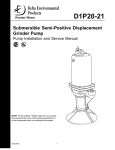
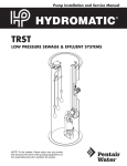
ECOFILTER PUMP VAULT ™ SEPTIC TANK PUMP VAULT FILTER SYSTEM SAFETY INSTRUCTIONS, INSTALLATION AND SERVICE MANUAL NOTE! To the installer: Please make sure you provide this manual to the owner of the equipment or to the responsible party who maintains the system. Part # 23833A630 | © 2012 Pentair Ltd. | 11/14/12 THANK YOU FOR PURCHASING YOUR DELTA PUMP VAULT SYSTEM. pumped by a high-head effluent STEP pump to the next stage of processing. DO NOT THROW AWAY THIS MANUAL. KEEP IT IN A SAFE PLACE SO THAT YOU MAY REFER TO IT OFTEN FOR THE CONTINUED SAFE OPERATION OF THE PRODUCT. Receiving the System: Remove pump vault, STEP pump, and components to be sure all items are included and inspect for possible concealed damage. Any damage should be reported immediately to the delivering carrier. Claims for damage must originate with the receiver. Claims for shipping damage cannot be processed at the factory. BEFORE INSTALLATION: This manual contains important information for the safe use of this product. Read this manual completely and follow the instructions carefully. Reasonable care and safe methods relating to the installation and operation of this product should be practiced. Check local codes and requirements before installation. Biohazard Risk. Once the wastewater source has been connected to system, biohazard risk exists. Installer(s) and/or service personnel must use proper Personal Protective Equipment and follow handling procedures per OSHA 29 CFR 1910.1030 when handling equipment after wastewater source has been connected to system. Failure to heed warnings and caution counld result in injury or death. n WARNING: BEFORE INSTALLING OR SERVICING YOUR PUMP, BE CERTAIN THE PUMP POWER SOURCE IS TURNED OFF AND DISCONNECTED. ONLY QUALIFIED PERSONNEL MAY INSTALL THIS SYSTEM. NFPA 70/NATIONAL ELECTRIC CODE (NEC) OR LOCAL CODES MUST BE FOLLOWED. THE SYSTEM MUST BE PROPERLY GROUNDED ACCORDING TO NEC. n WARNING: RISK OF ELECTRICAL SHOCK – TO REDUCE RISK OF ELECTRICAL SHOCK: • CONNECT ONLY TO A PROPERLY GROUNDED CONTROL PANEL. • DO NOT SMOKE OR USE SPARKABLE ELECTRICAL DEVICES OR FLAME IN ASEPTIC (GASEOUS) OR POSSIBLE SEPTIC SUMP. • DO NOT INSTALL PUMP IN LOCATIONS CLASSIFIED AS HAZARDOUS PER N.E.C., ANSI/NFPA 70 - 1999. n ADDITIONAL WARNINGS: • TANK SHOULD BE VENTED IN ACCORDANCE WITH LOCAL PLUMBING CODES • A SEPTIC SUMP CONDITION MAY EXIST AND IF ENTRY INTO SUMP IS NECESSARY, THEN (1) PROVIDE PROPER SAFETY PRECAUTIONS PER OSHA REQUIREMENTS AND (2) DO NOT ENTER SUMP UNTIL THESE PRECAUTIONS ARE STRICTLY FOLLOWED. • FOR USE WITH MAXIMUM 120°F WATER. This manual covers pump vault units of both 49" and 57" heights. Please make sure which system you are installing. The applicable size is determined by the depth of your septic tank. CALIFORNIA PROPOSITION 65 WARNING: This product and related accessories contain chemicals known to the State of California to cause cancer, birth defects or other reproductive harm. INSTALLATION INSTRUCTIONS Application: The pump vault is designed for installation into either a one- or two-chamber septic or pump tank to assist in the removal of filtered effluent. Effluent is screened to filter out all solids greater than 1/8". This screened effluent is then 23833A630 11/14/12 Vault System Handling: Factory built filter systems must not be dropped, dragged, rolled, or handled with sharp objects. Improper handling of filter systems may result in damage to the basin, damage to basin components, or leaks in the piping assemblies. Step 1: Determine the type of septic or pump tank you have. Concrete Tank: A 19" access hole is required in a concrete tank. A 24" or 30" diameter riser with a minimum height of 18" is required for use of the pump vault. Manufacturer’s instructions must be followed for riser installation to ensure a watertight seal. Fiberglass / Polyethylene Tank: These tanks typically have 24" diameter riser integral to the tank design. Refer to and follow manufacturer’s instructions if a riser of different diameter is needed (24" minimum diameter riser is required for use of the pump vault). Step 2 (Existing Tank use only): Empty and clean out the tank. Step 3: Lower the housing into the tank, resting the support pipes on the top of the tank. Step 4: Insert the preassembled 40" PVC pipe with pipe adapter (Figure 1, part A), pipe adapter end first, into the pump. Lower the pump into the pump chamber of the housing. Note: The chamber is designed to handle either one or two STEP pumps. A single pump can be located in either side of the chamber. Place a mark on PVC pipe “A” at the height necessary to be below frost line, per local code. Step 5: Position the rest of the discharge kit (Figure 1, part B) with the open end of the elbow beside the pipe marking. This determines the discharge exit location on the riser. Mark the location where the discharge pipe will exit on the riser. Remove the pump and discharge assembly. Using a properly maintained, 2-1/2" piloted hole saw, cut a hole in the riser at the marked location. Insert the flexible grommet (provided with the discharge kit) into the drilled hole. Step 6: Cut the PVC pipe (part A) at the marked location. Remove any shavings from the cut PVC pipe. Disassemble the union from part B. Use pipe cleaner to clean off the pipe and inside of the elbow from part B. Using PVC cement, attach the pipe and elbow. Step 7: Cement the remaining loose joints in the discharge kit (figure 1, part B). Several joints in the discharge kit are left uncemented at the factory to allow adjustments during instillation. Verify that all joints are properly cemented and leak free before puting the filter into service. Step 8: If you removed the discharge pipe from the pump to cut and assemble the kit, reattach it to the pump. Lubricate the inside lip of the discharge grommet with pipe soap. Slide the discharge pipe through the grommet. Reinstall the pump and discharge piping into the pump chamber. Align the assembly as shown in Figure 2 and assemble the union. Close the shutoff valve and attach the discharge pipe to the lateral field pipe with PVC solvent/cement. It is strongly recommended that an additional shut-off valve and redundant check valve be located The float tether length must be 2.5" as shown in figure 3 to avoid float failure. FILTER INSTALLATION Lower the filter assembly into the housing until it bottoms out. Turn the PVC latch to lock the filter in place (The filter must be installed in the housing before the pump vault assembly is installed). Junction Box Connections (when used) Step 1: Ensure power source is off or disconnected. Step 2: Install the junction box in the riser in a location which will not interfere with the removal of the filter. Step 3: Install a conduit seal outside the basin to prevent surface water from entering the junction box. Step 4: Push pump power and float cords through cord grips in the junction box and tighten the cord grips. To prevent corrosion or electrical short, plug any unused holes. Step 5: Remove junction box cover and make all connections inside junction box to all incoming alarm/control panel wires. Electrical Connections Note: Failure to use a manufacturer approved alarm or control panel voids the pump warranty and guarantee. IMPORTANT: Properly connect the panel ground wire to a grounding rod. Improper grounding voids warranty. outside the basin at any force main entrances - check local codes for specific requirements. Panel Wiring Ensure power source is off or disconnected. n WARNING: RISK OF ELECTRICAL SHOCK OR ELECTROCUTION. FAILURE TO HEED THE WARNINGS MAY RESULT IN SERIOUS INJURY, DEATH, OR FIRE HAZARD. THE INSTALLER MUST DISCONNECT ALL ELECTRICAL SOURCES PRIOR TO INSTALLATION. ONLY QUALIFIED PERSONNEL MAY INSTALL THIS SYSTEM. NFPA 70/NATIONAL ELECTRIC CODE (NEC) OR LOCAL CODES MUST BE FOLLOWED. SYSTEM MUST BE PROPERLY GROUNDED ACCORDING TO NEC OR LOCAL CODES. Follow the alarm/control panel installation instructions as provided by the manufacturer. n CAUTION: ALL LOCAL WIRING CODES MUST BE OBSERVED. CONSULT THE LOCAL INSPECTOR BEFORE INSTALLATION TO AVOID COSTLY DELAYS THAT CAN OCCUR DUE TO REJECTION AFTER THE JOB IS FINISHED. ONLY QUALIFIED ELECTRICIANS SHOULD MAKE THE INSTALLATION. COMPLETE WIRING DIAGRAMS ARE INCLUDED FOR USE IN MAKING THE INSTALLATION. ALL WIRES SHOULD BE CHECKED FOR SHORTS TO GROUND WITH AN OHMMETER OR MEGGER AFTER THE CONNECTIONS ARE MADE. THIS IS IMPORTANT, AS ONE GROUNDED WIRE CAN CAUSE CONSIDERABLE TROUBLE. • Septic tank or pump chamber is watertight PUMP INSTALLATION Follow STEP pump installation instructions for safe and correct pump operation. Float Tree Assembly The float tree assembly is shipped disassembled from the factory. The floats will be assembled to the float clips and pre-set to the 2.5" float tether length as required for proper operation. The float clips must be attached to the float tree in the proper positions in order to meet necessary reserve capacity, pump on level, pump off level, alarm level, and to meet local codes. The floats must be staggered 20 degrees as shown in figure 3 to ensure proper operation. START-UP CHECKS Before placing the pump into operation, verify the following: • Septic tank or pump chamber installed according to local regulations • Access riser and cover are installed according to manufac turer’s instructions and local regulations • Pump vault is installed according to instructions • Float tree is installed and wired into control panel • Float switches are free to move within vault housing • All electrical connections are watertight and conform to the National Electric Code (NEC) and state and local regulations Step 1: Run clean water into the septic tank or pump chamber. Step 2: Open the shut-off valve. Step 3: Turn the H-O-A switch to the Off position and turn on the main breaker. Step 4: Start the pump by turning the H-O-A switch to the Hand or Manual position. Step 5: Check the pump amperage with a clamp-on amp meter on the black pump lead. Readings higher than the nameplate indicate a clogged pump, miswiring, or improper voltage. Step 6: Ensure H-O-A switch is set to Auto before placing system into service. 23833A630 11/14/12 TYPICAL INSTALLATION CONTROL PANEL J - BOX LID SECURE EXCESS CORDAGE ACCESS RISER SHUT-OFF VALVE PREWIRED CONDUIT (PER LOCAL CODE) PIPE SEAL 11 DISCHARGE MUST FALL BELOW FROST LINE FROM GRADE PER LOCAL CODE FILTERED EFFLUENT SUPPORT PIPES 17" IN LENGTH 19" ACCESS OPENING [44.45] 1.75 MIN ALARM CONTROL [1447.8] 57.00 TALL HOUSING PUMP ON 1405.3 55 3/8" PUMP OFF ADJUSTABLE FLOAT COLLAR FILTER VAULT HOUSING SEPTIC TANK BALL CHECK Figure 2 63.5 2.50 20° Figure 3 23833A630 11/14/12 (2) CONFIGURATIONS AVAILABLE [1244.6] 49.00 SHORT HOUSING Below is a list of common problems and possible solutions. Refer to the pump and panel installation service manuals for details regarding any necessary adjusting, dismantling, or repair work. n WARNING: RISK OF ELECTRICAL SHOCK OR ELECTROCUTION. FAILURE TO HEED THESE WARNINGS MAY RESULT IN SERIOUS INJURY OR DEATH OR FIRE HAZARD. INSTALLER MUST DISCONNECT ALL ELECTRICAL SOURCES PRIOR TO INSTALLATION. ONLY QUALIFIED PERSONNEL MAY INSTALL OR SERVICE THIS SYSTEM. NFPA 70/NATIONAL ELECTRIC CODE (NEC) OR LOCAL CODES MUST BE FOLLOWED. SYSTEM MUST BE PROPERLY GROUNDED ACCORDING TO NEC OR LOCAL CODES. n WARNING: BEFORE INSTALLING OR SERVICING YOUR PUMP, BE CERTAIN THAT THE PUMP POWER SOURCE IS TURNED OFF AND DISCONNECTED. TROUBLESHOOTING Pump won’t run 1. Blown fuse, circuit breaker is in Off position, broken (or loose) electrical connections. Check fuses, breakers, and all electrical connections. 2. Motor overload protection contacts open. Contacts will close automatically within short time. 3. Low voltage. Check voltage at control panel. Pump runs, but no water pumped 1. Check valve installed backward. Reverse and reinstall. 2. The intake strainer is clogged. Remove the pump and clean the strainer. Reduced capacity 1. The strainer or impellers partially clogged or plugged. Remove the pump and clean the strainer. Basin level is pumped down with H-O-A in Hand or Manual position, but will not pump down in Automatic. 1. Floats are not hanging free in the basin or are covered with grease. Pump the level down with the H-O-A switch in Hand or Manual, so that the floats can be observed. Relocate and clean float(s) as necessary. 2. If this is a new installation and original start-up, the floats may be miswired in the control/alarm panel. If the On and Off floats are reversed, the pump will short-cycle On and Off and will not pump the level down. 3. Floats are malfunctioning. Pull the floats out of the basin and hang the Off and On floats from your hand. Turn the H-O-A switch to Auto. Tilt the Off float so that the large end is above the cord end (nothing should happen). While keeping the Off float tilted, tilt the On float in the same manner (the pump should come on). Suspend the On float again from your hand (the pump should continue to run). Finally, suspend the Off float from your hand (the pump should stop running). If this procedure does not cause the pump to operate as described, replace the float(s). n RISK OF FIRE OR EXPLOSION. DO NOT SMOKE OR USE OPEN FLAMES IN OR AROUND THIS SYSTEM. THIS SYSTEM IS NOT INTENDED FOR USE IN HAZARDOUS LOCATIONS PER NFPA 70 NATIONAL ELECTRIC CODE. CONSULT FACTORY FOR OPTIONAL EQUIPMENT RATED FOR THIS USE. n WARNING: BEFORE INSTALLING OR SERVICING YOUR PUMP, BE CERTAIN THAT THE PUMP POWER SOURCE IS TURNED OFF AND DISCONNECTED. The pump vault system requires periodic maintenance to ensure proper operation. SERVICE FREQUENCY The pump vault system prevents solids larger than 1/8" from entering drain lines. As a result, solids will periodically build up between the housing and filter. This requires the filter to be cleaned off. The service interval will depend upon usage patterns. At a minimum, the pump vault housing and filter should be cleaned each time the septic or pump tank is pumped out. Annual inspections by certified service personnel are recommended. Any high water alarm is an indication that attention to the system is required. Frequent high water alarm activation is an indication that system service is required. SERVICING THE SYSTEM The following tasks should be performed each time the pump vault system is serviced: Step 1: Turn off power to the system. Step 2: Check the sludge level of the septic tank. If the sludge level reaches the bottom of the pump vault housing inlet, the septic tank must be pumped out. Step 3: Remove the pump, clean off the pump screen, and inspect the pump for any damaged or malfunctioning components. Repair or replace components as necessary. Step 4: Remove the filter and remove any debris. Inspect the filter for damage. Replace the filter if there are any tears or breaks. Step 5: Remove any debris from the vault housing and inspect the housing for damage. Step 6: Reassemble the housing, filter and pump and reinstall in the tank. Step 7: Turn system power back on. Step 8: Test float and alarm/control panel operation and repair/ replace any malfunctioning components. n BIOHAZARD RISK. ONCE THE WASTEWATER SOURCE HAS BEEN CONNECTED TO SYSTEM, BIOHAZARD RISK EXISTS. INSTALLER(S) AND/OR SERVICE PERSONNEL MUST USE PROPER PERSONAL PROTECTIVE EQUIPMENT AND FOLLOW HANDLING PROCEDURES PER OSHA 29 CFR 1910.1030 WHEN HANDLING EQUIPMENT AFTER WASTEWATER SOURCE HAS BEEN CONNECTED TO SYSTEM. 23833A630 11/14/12 4 2 1 3 No. 5 Description 49" 57" 1 Housing 27623D003 27623D004 2 Filter Assembly 27628D001 27624D002 3 Float Tree w/ Floats 27628D001 27628D002*** 4 Discharge Kit* 27418A805 27418A805*** 5 Effluent Pump** D4E30M-10 D4E30M-10 *Discharge kit includes union, ball valve, pipe, and pump/pipe adapter. ** Consult factory for available pump sizes. *** Available in Duplex configuration, consult factory for details. No. 3 – Other float tree configurations available, consult factory for details. 23833A630 11/14/12 THIS PAGE INTENTIONALLY LEFT BLANK LIMITED WARRANTY Delta Environmental warrants the parts in each treatment system for a limited two year period. All warranty questions shall be resolved through Delta Environmental. The warranty on the treatment device is that the device is free from defects in material and workmanship from the date of installation treating household wastewater. Some states do not allow limitations on how long an implied warranty lasts, so the above limitation may not apply. Sole obligation under this warranty is as follows: Delta Environmental shall fulfill this warranty by repairing or exchanging any component part, F.O.B. factory that in Delta Environmental judgment shows evidence of defects, provided said component part has been paid for and is returned through an authorized dealer, transportation prepaid. The warrantee must also specify the nature of the defect to the manufacturer. The warranty does not cover treatment processes/devices that have been flooded, by external means, or that have been disassembled by unauthorized persons, improperly installed, subjected to external damage or damaged due to altered or improper wiring or overload protection. This warranty applies only to the treatment process/device and does not include any of the house wiring, plumbing, drainage, or disposal system. Delta Environmental is not responsible for any delay or damages caused by defective components or material, or for loss incurred because of interruption of service, or for any other special or consequential damages or incidental expenses arising from the manufacture, sale or use of this process/device. Delta Environmental reserves the right to revise, change or modify the construction and design of the treatment process/device for household wastewater or any component part or parts thereof without incurring any obligation to make such changes or modifications in previously sold equipment. Delta Environmental also reserves the right, in making replacements of component parts under this warranty, to furnish a component part which, in its judgment is equivalent to the part replaced. Under no circumstances will Delta Environmental be responsible to the warrantee for any other direct or consequential damages, including but not limited to lost profits, lost income, labor charges, delays in production, and/or idle production, which damages are cause by a defect in material and/or workmanship in its parts. Some states do not allow the exclusion of limitation of incidental or consequential damages, so the above limitation or exclusion may not apply to you. This warranty is expressly in lieu of any other express or implied warranty, excluding any warranty of merchantability or fitness and of any other obligation on the part of Delta Environmental. This warranty gives you specific legal rights, and you may also have other rights which vary from state to state. Delta Environmental 8263 Florida Blvd. Denham Springs, LA 70726 1-800-219-9183 Warranty Rev 05/12