1
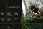
READ THIS MANUAL CAREFULLY!
It contains important safety information.
Keep it for future reference.
slice carbon
Owner’s Manual Supplement
120849.PDF
CONTENTS
safety information ................................ 1
About This Supplement........................... 2
Important Composites Message........... 3
Intended Use................................................ 3
Building Up A Frameset............................ 4
Extreme Temperatures.............................. 4
Bike Stands.................................................... 4
Inspection and Crash Damage.............. 5
Repainting and Refinishing.................... 5
Serial Number . ............................................ 6
SI BOTTOM BRACKET SHELL ....................12
Compatibility.............................................12
Bearings......................................................... 9
SI Tools..........................................................11
68mm Standard Adapter.......................12
SI compression Assembly . .................14
cable routing.............................................. 6
GEOMETRY/SPECIFICATION . ...................18
SEAT POST.......................................................... 8
Saddle Position/Angle.............................. 8
80mm MINIMUM INSERT......................... 9
Cutting the Seat Post................................ 9
Seat Post Parts...........................................10
Changing Saddle Position.....................11
REPLACEMENT PARTS..................................19
Chainstay protection...........................16
REAR DERAILLEUR HANGER ....................16
REAR BRAKE MOUNT ADAPTER...............17
Please note that the specifications and information in this manual are subject to change for
product improvement. For the latest product information, go to http://www.cannondale.
com/tech/.
SAFETY
INFORMATION
WARNING
About This Supplement
Cannondale Owner’s Manual Supplements
provide important model specific safety,
maintenance, and technical information. They
are not replacements for your Cannondale
Bicycle Owner’s Manual.
This supplement may be one of several for
your bike. Be sure to obtain and read all of
them.
If you need a manual or supplement, or have a
question about your bike, please contact your
Cannondale Dealer immediately, or call us at
one of the telephone numbers listed on the
back cover of this manual.
You can download Adobe Acrobat PDF
versions of any Cannondale Owner’s Manuals
or Supplements from our website: http://www.
cannondale.com/bikes/tech.
• This manual is not a comprehensive
safety or service manual for your bike.
• This manual does not include assembly
instructions for your bike.
• All Cannondale bikes must be completely
assembled and inspected for proper
operation by a Cannondale Dealer before
delivery to the owner.
This supplement may include procedures
beyond the scope of general mechanical
aptitude.
Special tools, skills, and knowledge may
be required. Improper mechanical work
increases the risk of an accident. Any
bicycle accident has risk of serious injury,
paralysis or death. To minimize risk
we strongly recommend that owners
always have mechanical work done by an
authorized Cannondale retailer.
WARNING
IMPORTANT COMPOSITES MESSAGE
Your bike is made from composite materials
also known as “carbon fiber.”.
All riders must understand a fundamental
reality of composites. Composite materials
constructed of carbon fibers are strong
and light, but when crashed or overloaded,
carbon fibers do not bend, they break.
For your safety, as you own and use the
bike, you must follow proper service,
maintenance, and inspection of all the
composites (frame, stem, fork, handlebar,
seat post, etc.) Ask your Cannondale Dealer
for help.
We urge you to read PART II, Section D.
“Inspect For Safety” in your Cannondale
Bicycle Owner’s Manual BEFORE you ride.
YOU CAN BE SEVERELY INJURED,
PARALYZED OR KILLED IN AN ACCIDENT
IF YOU IGNORE THIS MESSAGE.
120849.PDF
Intended Use
WARNING
The intended use of your bike or frameset is
CONDITION 1 / HIGH PERFORMANCE ROAD.
UNDERSTAND YOUR BIKE AND ITS
INTENDED USE. CHOOSING THE WRONG
BICYCLE FOR YOUR PURPOSE CAN BE
HAZARDOUS. USING YOUR BIKE THE
WRONG WAY IS DANGEROUS.
Industry usage Conditions 1 - 5 are
generalized and evolving. Consult your
Cannondale Dealer about how you intend
to use your bike.
Please read your Cannondale Bicycle
Owner’s Manual for more information
about Intended Use and Conditions 1-5.
For riding on
pavement
only
Maximum Weight Limit
CONDITION 1 / HIGH-PERFORMANCE ROAD
bikes and framesets are designed for riding
on a paved surface where the tires do not lose
ground contact. They are not intended to be
ridden off-road, cyclocross, or touring with
racks or panniers.
RIDER
lbs / kg
LUGGAGE *
lbs / kg
TOTAL
lbs / kg
275 / 125
10 / 4.5
285 / 129
* Seat Bag /Handlebar Bag Only
Material use is optimized to deliver both
light weight and specific performance. You
must understand that (1) these types of bikes
are intended to give an aggressive racer or
competitive cyclist a performance advantage
over a relatively short product life, (2) a less
aggressive rider will enjoy longer frame life, (3)
you are choosing light weight (shorter frame
life) over more frame weight and a longer
frame life, (4) you are choosing light weight
over more dent resistant or rugged frames
that weigh more. All frames that are very
light need frequent inspection for cracks that
would indicate that the frame is worn out from
fatigue. These frames are likely to be damaged
or broken in a crash. They are not designed to
take abuse or be a rugged workhorse.
Building Up A Frameset
Bike Stands
The clamping jaws of ordinary bike stand can
generate a crushing force strong enough to
seriously damage and ruin your bike frame.
Before building up a frameset, consult with
your Cannondale Dealer and the component
manufacturers, and discuss your riding style,
ability, weight, and interest in and patience for
maintenance.
CAUTION
SERIOUS FRAME DAMAGE:
Make sure the components chosen are
compatible with your bike and intended for
your weight and riding style.
DO NOT USE STANDS THAT CLAMP TO THE
FRAME OR SEAT POST.
USE A STAND THAT RELIES ON SUPPORTING
THE BOTTOM BRACKET AND DROPOUTS.
(Park Tool, PRS-20 shown)
Generally speaking, lighter weight components
have shorter lives. In selecting lightweight
components, you are making a trade-off,
favoring the higher performance that comes
with less weight over longevity. If you choose
more lightweight components, you must
inspect them more frequently. If you are a
heavier rider or have a rough, abusive or “go for
it” riding style, buy heavy duty components.
Read and follow the component manufacturers
warnings and instructions.
Protect From
Extreme Temperatures
• Protect your carbon bike from extreme
temperatures when storing or transporting it.
• Allow your bike to cool off or warm up before
you ride
• Do not store your bike in places where the
temperature will exceed 66.5C° (150°F). For
example, do not leave your bike lying flat in
a black pickup truck bed in the desert sun or
under the glass of a hatchback auto.
120849.PDF
Inspection & Crash
Damage of Carbon Frames
WARNING
AFTER A CRASH OR IMPACT:
Inspect frame carefully for damage (See
PART II, Section D. Inspect For Safety in your
Cannondale Bicycle Owner’s Manual.)
Repainting Or Refinishing
You should not paint over the existing finish,
refinish or repaint your bike. The carbon fiber
composites making up the frame are held
together by some extremely strong bonding
chemicals. However, these bonds can be
attacked or weakened by paint stripping or
refinishing chemicals.
WARNING
Do not ride your bike if you see any sign
of damage, such as broken, splintered, or
delaminated carbon fiber.
Repainting, painting over, retouching, or
refinishing your frame or fork can result in
severe damage leading to an accident. You
can be severely injured, paralyzed or killed.
ANY OF THE FOLLOWING MAY INDICATE
A DELAMINATION OR DAMAGE:
Refinishing chemicals : Solvents, and
strippers can attack, weaken, or destroy
the important composite chemical bonds
holding your frame together.
An unusual or strange feel to the frame
Carbon which has a soft feel or altered
shape
Creaking or other unexplained noises,
Using abrasives or sanding the frame/fork
structure, original paint, decals, or coatings
through the use of mechanical actions
such as plastic or glass bead blasting or
other abrasive methods such as sanding
or scraping can remove frame material or
weaken it.
Visible cracks, a white or milky color present
in carbon fiber section
Continuing to ride a damaged frame
increases the chances of frame failure,
with the possibility of injury or death of
the rider.
1
3
2
serial number
The serial number (1) printed and permanently affixed barcode label. Use this serial number for
warranty registration and theft recovery. See your Cannondale Bicycle Owner’s Manual for more
information on warranty registration.
cable routing
The rear and front derailleur cables exiting the
down tube (2) are routed through the bottom
bracket cable guide (3).
Extension
The top tube guide is removable so that brake
cable may be routed inside the tube. The guide
is secured in the tube opening by the installed
brake cable tension. Make sure the guide is
seated properly in the top tube opening when
installing and connecting the rear brake.
BB Guide
Be sure to use a ferrules on housing ends.
When installing cables, make sure ferrule is seated
inside frame opening correctly.
KF363/
Screw
120849.PDF
Rear Brake Housing
Rear Brake Frame Opening
Cable
Ferrule
Front Derailluer Frame Opening
Cable
Ferrule
Top Tube Opening
Brake Housing
Rear
Brake
Cable
KP063/
Guide
Ferrule
seat post
6 Nm
Tighten both
clamp bolts evenly
MINIMUM INSERT
80mm
6 Nm
Clean and apply
Carbon seat post gel (kf115/)
to the post before
inserting into frame
Saddle Position and Angle
The seat post can be configured to place the saddle in a TRIATHLON or TIME TRIAL position.
Please see “Changing Saddle Position” on pages 9 and 10. The water bottle cage bracket parts
can only be used with saddle in the TRIATHLON position (shown above). Two water bottle cages
may be mounted on the sides of the seat post, or a single cage can be mounted on the back.
Saddle angle can be adjusted by rotating the upper saddle clamp 180°. The change is 3° per
groove. If the upper saddle clamp orientation is reversed 180°, saddle adjustment range will
change ±1.5° in relation to 0° , again with 3° of change per groove. Ask a professional bike
mechanic to show you how this works.
120849.PDF
80mm Minimum Insert
The minimum insert depth that the seat post must be inserted into the frame is 80mm. Seat
posts are permanently marked with ‘MINIMUM INSERT” line 80mm up from the bottom of an
un-cut seat post.
Cutting the Seat Post
In some frames (especially smaller sizes), a seat post will only be able to be inserted into a seat tube
to a maximum depth of 100 mm. Below a depth of 100mm carbon material can interfere with the
seat post. The material can not be removed.
The full length of the seat post can be cut down to have sufficient adjustment range. The minimum
insertion depth requirement of 80mm does not change. 80mm should be marked from the bottom
of a cut seat post. The seat post may be cut (shortened). A new “MINIMUM INSERT” line 80mm
from the bottom of the post must be marked or indicated without scoring, scratching or
otherwise damaging the surface of the seat post. Use a thin decal (automotive pin striping) or
permanent marker.
WARNINGS
TO AVOID SERIOUS SEAT POST OR FRAME DAMAGE:
1.After any crash, fall, or impact, remove and inspect the seat post for damage (e.g., cracks,
scratches, scrapes, gouges, splintering). If damage is found, do not ride it; discard it.
Replace the seat post with a new one.
2. Do not use solvents, or chemical spray cleaners to clean.
3.Never force a seat post into the seat tube.
4. Use a good torque wrench to tighten fasteners to the specified torque. Correct tightening
torque of the seat post clamp and the bolts that hold the saddle to the seat post is also
very important to your safety. Always tighten seat post to saddle clamp bolts to the correct
torque. Bolts that are too tight can stretch and deform. Bolts that are too loose can move,
fatigue and fracture. Either mistake can lead to a sudden failure of these bolts. Such a
failure may lead to an accident, with risk of serious injury, paralysis or death.
5.If the seat post requires cutting, have it done by a professional bike mechanic with
experience cutting high-performance carbon components.
YOU CAN BE
WARNINGS.
SEVERELY INJURED, PARALYZED OR KILLED IF YOUR IGNORE THESE
6.
7.
5.
4.
8.
9.
3.
6 Nm
2.
6 Nm
1.
REFLECTOR
6 Nm
FORW
ARD
KP062/
10
2008 SLICE MULTISPORT SEATPOST
Water Bottle Bracket Assembly Update Parts
To obtain the update parts,
please contact a Cannondale Dealer.
6Nm
SMALL FOAM WASHER
Affix the washer to arm at contact with post.
6Nm
LARGE FOAM WASHERS
Position between seat post and brackets.
Please consult the Cannondale SLICE CARBON Owner’s Manual Supplement 120849.PDF
for seat post installation and service information. See www.cannondale.com/tech.
120849.PDF
TIME TRIAL
TRIATHALON
Changing Saddle Position
1. Remove the saddle clamp bolts (2) and
remove clamp barrel (3), upper clamp
(9), lower clamp (8), and barrel (4).
3.Remove the circlips (6).
Single
rear facing
cage
4. Reposition clamp over (5) and use
other pin (7) and reinstall pin and
all four circlips (6). Make sure all four
circlip are seated in the pin grooves.
5. Reinstall the saddle, clamp bolts, and
tighten the clamp bolts evenly to the
specified torque.
Twin side facing cages (shown).
FORW
ARD
11
si bottom bracket
Compatibility
The BB shell is compatible with the BB30 Standard. See http://www.bb30standard.com/ For
information see SI Cranksets Owner’s Manual Supplement. See http://www.cannondale.com/
tech/.
Bearings
Shell bearings are sealed cartridge type and do not require lubrication. Inspect bearing
condition annually (at a minimum) and anytime the crankset assembly is disassembled or
serviced. The bearings are a press fit within the shell. Old bearings should not be reinstalled if
removed. Replace both bearings at the same time.
Replacements circlips (QC616/) are available if the circlips become damaged. The circlips can be
lifted from the BB groove (inset) by lifting the hooked end with a thin blade screwdriver.
CAUTION
DO NOT FACE, MILL OR MACHINE THE BOTTOM BRACKET SHELL FOR ANY REASON.
Doing so can result in serious damage and possibly a ruined bike frame.
SI Tools
KT011/ is a bearing removal tool.
KT010/ is a set of bearing installation tools to be used with a standard headset press.
KT013/ a two piece tool set required for removing the crankarms SI Hollowgram alloy cranksets.
For information see SI Cranksets Owner’s Manual Supplement.
com/tech/.
See http://www.cannondale.
SI BB30-to-68mm Standard Adapter
The adapter (Cannondale kit KF365/) converts the BB30 bottom bracket cranksets for use with
68mm bottom brackets. The adapter IS NOT a repair part and will only work in undamaged
frames in good condition. Improper installation or removal can result in damage and void
applicable frame warranty.
CAUTION
SERIOUS FRAME DAMAGE : Once installed, the SI-to-Standard adapter is a non-removable/
permanent frame part. Do not remove it. Adapters must be installed by a professional bike
mechanic.
12
120849.PDF
QC616/
KB6180/
KP018/ (ceramic)
KT011/
KT010/
KT013/
TOOL
Loctite 609
(green)
groove
TOOL
BB SHELL
8mm
ADAPTER
KF365/
DRIVE SIDE
13
si compression assembly
The cylindrical shape of the TOP CAP fits snugly within the carbon steering tube inside diameter
(I.D.), supporting the steerer from the clamping force of the stem. It must fit snugly inside the
I.D. of the steerer.
How to install the assembly
1.Assemble the fork, headset, spacers, and stem. Make sure that the stem bolts are loose.
2.Set up the compression assembly. “READY TO INSERT” above. The length should be about
48mm as shown above. You can do this by unthreading the top cap from the expander and
then threading it back on about 6-7 turns. The expanding parts should not be expanded.
3. Insert the SI compression assembly into the fork steerer. It should slide in snugly; the TOP
CAP closely fitting the steerer inside diameter.
4. Insert a 5mm Allen key through the access hole in the TOP CAP and into the EXPANDER BOLT.
Tighten the expander by turning clockwise to 6.8Nm, 5 ftLbs.
5.To set bearing preload, insert a 6mm allen key into the hex shape in the TOP CAP iteself.
Turn the entire TOP CAP clockwise to increase preload. Turn counter-clockwise to decrease
preload.
6. When the headset preload is correct, align handlebar and tighten the stem fork clamp bolts
to the torque specified for the stem. Consult the stem since torque values are often marked
on the stem, or consult the manufacturer’s instructions.
WARNINGS
USE ONLY ORIGINAL EQUIPMENT CANNONDALE SI COMPRESSION ASSEMBLY. Do not
replace it with a star nut or use any other compression or expanding wedge assembly.
DO NOT INSTALL HEADSET SPACERS ON TOP OF THE STEM. Installing spacers above the
stem will raise the TOP CAP inside the steerer removing necessary support for the steerer
tube wall. When stem bolts are tightened. the steerer tube can be damaged.
PLACE HEADSET SPACERS ONLY BETWEEN THE HEADTUBE AND THE BOTTOM OF THE
STEM.
YOU CAN BE SEVERELY INJURED, PARALYZED OR KILLED IF YOUR IGNORE THESE
WARNINGS.
14
120849.PDF
6mm
EXPLODED VIEW
TOP CAP
“READY TO INSERT”
5mm
EXPANDER BOLT
6.8N•m, 5 Ft•Lbs
KP017/
48mm
EXPANDER
Do not grease.
Cut the steerer tube
2 - 3mm below the top
of the installed stem.
CARBON
STEERER
TUBE
HEADSET SPACERS
Thread on TOP CAP.
Set EXPANDER BOLT
so that the the expanding parts are not
expanded and not loose.
STEM
55mm
HEADSET TOP CAP
MAXIMUM STACK HEIGHT
Measure from the top edge of the headtube
to the bottom edge of the stem.
HEADTUBE
For more information on Cannondale Carbon Road Forks, please see your Carbon
Road Fork Owner’s Manual Supplement 120860.pdf included with your bike or
download it from our website http://www.cannondale.com/tech_center/
15
KP065/
chainstay protection
The chainstay plate (KP065/) located on the right chainstay just behind the chain rings, protects
the chainstay from damage in the event the chain is dropped from the chain ring. Contact your
Cannondale Dealer for a replacement if it is becomes missing or damaged. The clear chainstay
protector (above right) provides limited protection against frame or finish damage caused by
the chain. Replacement protectors are available through a Cannondale Dealer.
rear derailleur
hanger
1.1 Nm, 10 InLbs
Loctite 242 (blue)
Before re- installing (same or new): Clean
dropout and inspect carefully for any cracks or
damage. Clean surfaces and apply a light film
of bike grease to the dropout to minimize any
noise or “creaking” that might result from very
slight movement between the dropout and
hanger during movement of the derailleur.
Apply grease and Loctite carefully. Do not
contaminate the male or female bolt threads
with grease which would cause the Loctite to
be ineffective.
Check derailleur adjustment after
replacement. Readjust wheel quick release
so it is very tight. See PART I Section 4. A in
your Cannondale Bicycle Owner’s Manual.
LIGHT
GREASE
2.5 mm
KF096/
CAUTION
DO NOT USE A DERAILLEUR HANGER
ALIGNMENT TOOL TO STRAIGHTEN.
16
120849.PDF
rear brake
mount adapter
To install a rear brake:
1.Remove the adapter bolt (1) with a 4mm
Allen wrench.
2. Lift the brake mount adapter (2) from the
frame.
2
3.Install a serrated washer (3) onto the
brake bolt and mount the brake onto the
adapter.
Tighten the brake recessed nut (4) to
the brake manufacturer’s recommended
torque.
4
4. Apply grease to adapter bolt threads and
install adapter and brake into frame.
Tighten adapter bolt to 7 Nm.
2
3
Replacement brake mount kit - KP064/
1
4mm
17
geometry/specification
A
REACH
B
STACK
M
J
K
F
L
E
D
G
C
H
ITEM
Wheel Size
Horizontal Top Tube Length (cm)**
Measured Size (cm)
Seat Tube Angle*
Head Tube Angle
Chainstay Length
Fork Rake
Bottom Bracket Height (cm)
Wheelbase (cm)
Trail (cm)
Standover @ Top Tube Midpoint
Bottom Bracket Drop (cm)
Front Center Distance (cm)
Head Tube Length (cm)
STACK (cm)***
REACH (cm)***
Headset Compression
Seatpost Minimum Insert Depth.
Seat Binder
Rear Brake Mount Adapter Bolt
Dropout Spacing
51
54
56
56
700c
700c
700c
700c
A
50.5
53.5
55.0
56.5
B
50
51.5
53.5
55.5
C
75°
75°
75°
75°
D
71.5°
71.5°
72°
72°
E
40
40
40
40
F
4.5
4.5
4.5
4.5
G
26.5
26.5
26.5
26.5
H
95.4
98.5
99.7
101.3
I
6.5
6.5
6.2
6.2
J
74.9
76.4
78.3
80.2
K
72
72
72
72
L
56.5
59.6
60.7
62.3
M
9.0
10.5
12.5
14.5
49.4
50.9
52.9
54.8
37.1
39.8
40.7
41.7
Cannondale SI Compression Assembly - KP017/
80mm
KP062/
MAXIMUM TORQUE
7Nm
Rear 130mm, Front 100mm
60
700c
58.0
57.5
75°
72°
40
4.5
26.5
102.6
6.2
82.2
72
63.9
17
57.2
42.5
6Nm
* The Slice seat post has two positions for mounting the saddle. A full range of angles from 73° to 78° is achievable depending on rider’s preference and/or the event.
** This is the actual measurement of the top tube. The distance from the saddle to the bars will vary based on the choice of seat post position.
*** STACK and REACH - STACK is measured vertically from the center of the BB to the top of the head tube; REACH is measured horizontally from the center of the
BB to the top of the head tube.
If you ride a 56 road frame, you should choose a size 56 Slice frame.
18
120849.PDF
replacement parts
ORDER
FRAME
KF363/
KF055/
KP061/
KP062/
KP060/
KF115/
KP065/
KF096/
KP064/
BB CABLE GUIDE w/fixing bolt
INLINE ADJUSTER (QTY 2)
SEAT POST SLICE AERO
SEAT BINDER SLICE AERO
SEAT POST HARDWARE SLICE AERO
SEAT POST GEL
CHAINSTAY PROTECT-AERO SLICE
REAR DERAILLUER HANGER
BRAKE GUIDE SLICE AERO
ORDER
KB002/
QC778/
KP017
HEADSET & FORK PARTS
KIT,HEADSET,SI CRB W/15 TC
BRAKE BOLT(35mm)
SI COMPRESSION ASSY
ORDER
SI BB30
BOTTOM BRACKET
SI CIRCLIPS (QTY 2)
SI BEARINGS (QTY 2)
SI CERAMIC BEARINGS (QTY 2)
SI BEARING SHIELD (QTY 2)
SI BEARING SHIELD SL (QTY 2)
SPINDLE-SI ROAD
SI SHIMS (QTY 5)
SI WAVE WASHER
TOOLS
SI BEARING PRESS TOOL(USED WITH HEADSET PRESS)
SI BEARING REMOVAL TOOL
SI LOCKRING TOOL
SI HOLLOWGRAM CRANKARM EXTRACTION TOOL
SIBB/68 ADP.INSTALL
EXTRACT CAP TOOL FOR SI CARBON CRANKSETS
ADAPTER,SIBB TO 68MM TAP
QC616/
KB6810/
KP018/
QC615/
KP023/
QC612/
QC617/
QC618/
KT010/
KT011/
KT012/
KT013/
KF365/
QC787/
KP009/
For an up to date list of kits available for your bike, please visit our Tech Center at : http://www.cannondale.
com/bikes/tech/
19
ORDER
SI HOLLOWGRAM
KA014/170SLV
KA014/172SLV
KA014/175SLV
KA015/170SLV
KA015/172SLV
KA015/175SLV
KP019/170L
KP019/172L
KP019/175L
KP019/170R
KP019/172R
KP019/175R
QC690/
QC850/
KA019/
ORDER
QC781/
QC782/
QC783/
QC784/
QC785/
QC786/
KF361/
QC787/
ORDER
QC694/
QC693/
QC603/
KP024/
KP025/
KP026/
KP027/
KP021/
QC789/
QC790/
QC791/
QC792/
QC788/
SI HOLLOWGRAM CRANKSETS
CRANKSET,SL,ROAD 39/53,170
CRANKSET,SL,ROAD 39/53,172
CRANKSET,SL,ROAD 39/53,175
CRANKSET,SL,ROAD 34/50,170
CRANKSET,SL,ROAD 34/50,172
CRANKSET,SL,ROAD 34/50,175
CRANKARM-SL SLV,170 LFT
CRANKARM-SL SLV,172 LFT
CRANKARM-SL SLV,175 LFT
CRANKARM-SL SLV,170 RHT
CRANKARM-SL SLV,172 RHT
CRANKARM-SL SLV,175 RHT
BB,CDALE Si,68X104mm Rd
B,CDALE Si,68X104mm Rd-SRM
BB,CDALE Si,68X104 CERAMIC
SI CARBON
CRANKSET,CRB 2PC,39/53,170
CRANKSET,CRB 2PC,39/53,172
CRANKSET,CRB 2PC,39/53,175
CRANKSET,CRB 2PC,34/50,170
CRANKSET,CRB 2PC,34/50,172
CRANKSET,CRB 2PC,34/50,175
BOLTS, SI CARBON CRANK (QTY 2)
TOOL-EXTRACT. CAP.SI CRB
SI CHAINRINGS/SPIDER
Spider,H-GRAM SI,130MM BCD
Spider,H-GRAM SI,110mm BCD
Pin,Chain Catch-SI
CHAINRING,MK5-53T/130BCD
CHAINRING,MK5-39T/130BCD
CHAINRING,MK5-50T/110BCD
CHAINRING,MK5-34T/110BCD
LOCKRING-SL --REQUIRES KT012/
CHAINRING,SI,39T/130BCD
CHAINRING,SI,53T/130BCD
CHAINRING,SI,34T/110BCD
CHAINRING,SI,50T/110BCD-34Tspecific
BB,CDALE SI,2PC
20