1
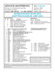
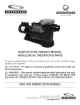
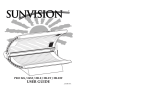
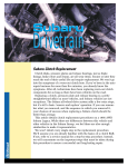
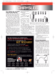
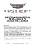
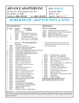
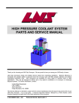
CORVETTE 1963 – 1967 RS 5-SPEED RS400 – RS500 – RS600 TRANSMISSION CONVERSION INSTALLATION MANUAL KEISLER ENGINEERING, INC FOLLOW FACTORY SERVICE MANUAL (FSM) RECOMMENDED SAFETY PRECAUTIONS. TRANSMISSION REMOVAL AND INSTALLATION IS A LABOR INTENSIVE JOB, WHICH CAN RESULT IN SERIOUS INJURY OR DEATH IF CAUTION IS NOT TAKEN. PLEASE BE CAREFUL PERFORMING THIS JOB, OR HAVE A PROFESSIONAL PERFORM THE JOB FOR YOU. REFER TO FACTORY SERVICE MANUAL (FSM) FOR ADDITIONAL DETAILS OF THE PROCEDURES BELOW, AS REQUIRED. FOR BOLT TORQUE SPECIFICATIONS, REFER TO YOUR FACTORY SERVICE MANUAL. The material herein is the intellectual property of Keisler Engineering, Inc. and is to be used by Keisler customers or their authorized installers for the sole purpose of installing Keisler-supplied transmissions and related parts. Under no circumstances shall the manual or any portion thereof be copied, duplicated, distributed or incorporated in any written or printed document without the express written approval of Keisler Engineering, Inc. Before you start: Test drive the vehicle, if possible, before you begin. Pay attention to noise and vibration and record your observations. At the end of the installation, perform another test drive to compare. In addition to this manual, you should have received instructions for checking your bellhousing runout. The bellhousing runout must be checked (and corrected if necessary) for warranty coverage. You should also verify the parts you received. Compare the received items to the detailed invoice provided in your shipment. PLEASE READ ALL INSTRUCTIONS BEFORE INSTALLATION In addition to these instructions, you should receive the following instructions based on your order, if applicable: 1. All kits: MAA-00101 Inspection and Correction of Bellhousing to Crankshaft Runout 2. Hydraulic throw out bearing kit: MAG-00402 Hydraulic Kit Instructions for GM 3. MAA-00201: Automatic to Manual conversion, General Guidelines Your invoice lists the individual hardware packs and where they are used. NOTE: Transmission must be test shifted before installation. Please make sure that the gear selector will move into each of the six possible positions while rotating the input shaft and checking for output shaft rotation. If the input shaft will not turn, slide the clutch disc over the input shaft and jerk the clutch disc left and right to break it free. If this does not correct the issue, call Keisler Engineering at 865-609-8187 extension 2 for instructions. THIS CANNOT BE CORRECTED WITH THE TRANSMISSION INSTALLED IN THE CAR! TEST SHIFT FIRST! MAG-05602, Corvette 1963-1967 RS Installation Manual, Rev 0, 08/22/11 2 KEISLER ENGINEERING, INC If your car was originally equipped from the factory with a 4-speed and a welded-in transmission support crossmember, the engine must be removed in order to install the RS transmission. The transmission and engine may be bolted together and installed as an assembly, or the transmission may be installed separately first. These instructions assume that you will be installing the engine and transmission as a unit. Consult your factory service manual for the engine removal procedure. For factory automatic equipped original vehicles, the crossmember is removable and the installation of the RS does not require engine to be removed. Both fixed and removable crossmembers use the same crossmember transmission mount perch. NOTE: If you are converting from an automatic transmission, you will want to install the new speedometer cable in the dash while you have the pedal assembly removed. A. REMOVE EXISTING EQUIPMENT With welded-in crossmember: Follow the procedure in your factory service manual, but here are the basic steps to remove the engine and manual transmission: 1. Disconnect negative (-) battery cable. 2. Remove LH & RH interior side panels from console. 3. Remove console top plate. Disconnect power window switch connector, if equipped (note orientation of connection). Remove power window switch heat shield cup and switch, if equipped. 4. Remove shifter knob & boot. Place shifter in neutral. 5. Mark the position of the hood hinges on the hood, and remove the hood. 6. Remove engine cooling fan and fan shroud. 7. Drain engine coolant into a suitable container and dispose of properly. 8. Disconnect the heater hoses, upper and lower radiator hoses, and remove radiator. 9. Disconnect fuel line at fuel pump, being careful to catch and properly dispose of any spilled fuel. 10. Label and disconnect all engine wiring. 11. If vehicle has air conditioning, you may be able to unbolt the compressor and move it out of the way with the lines still attached. If not, evacuate the A/C system and disconnect the hoses. 12. Remove breather assembly & ignition cluster cover/distributor cap from engine. 13. Disconnect mechanical tachometer drive from distributor, if equipped. 14. Disconnect throttle linkage from engine. 15. Raise car securely on lift or jack stands. 16. Drain transmission fluid into a suitable container and dispose of properly. 17. Disconnect exhaust pipes at manifold and remove as required for working clearance. If using under-car exhaust, disconnect from the support bracket at the transmission crossmember. 18. Remove linkage pin & clip at torque arm (z-bar) to clutch fork. 19. Remove driveshaft at front yoke, then at rear differential. 20. Remove shifter assembly. 21. Remove speedometer cable. 22. Disconnect reverse lamp wiring. 23. Support rear of transmission with hydraulic jack. 24. Remove transmission mount bracket. 25. Lower transmission so that it rests on the crossmember. 26. Support engine with hoist, and remove engine mount bolts. 27. Make sure all wiring, hoses, and linkage are disconnected from both the engine and transmission, and then remove engine/transmission assembly from the vehicle. 28. Remove inspection cover from front of bellhousing. 29. Unbolt transmission from bellhousing and slide rearward out of bellhousing. MAG-05602, Corvette 1963-1967 RS Installation Manual, Rev 0, 08/22/11 3 KEISLER ENGINEERING, INC 30. Remove bellhousing and clutch unit from engine. 31. Remove clutch fork and release bearing from bellhousing. Inspect release bearing, fork, and pivot ball stud for wear. Replace if needed. 32. Inspect flywheel ring gear teeth (no cracks, chips, wear), and friction surface (no cracks, grooves, or hot spots). Keisler Engineering strongly suggests removing flywheel and having it resurfaced, then dynamically balanced at a reputable automotive machine shop unless the engine was externally balanced with the flywheel installed. 33. Remove pilot bushing using removal tool (not supplied). 34. Remove factory tunnel insulation, if equipped. 35. Some manual transmission cars came with a safety mechanism that only allows the key to be removed if the transmission is in Reverse. This system must be disabled or “fixed” so that the key can be removed at any time. With bolted-in crossmember: Follow the transmission removal procedure in your factory service manual, but here are the basic steps to remove an automatic transmission: 1. Disconnect negative (-) battery cable. 2. Remove LH & RH interior side panels from console. 3. Remove console top plate. Disconnect power window switch connector, if equipped (note orientation of connection). Remove power window switch heat shield cup and switch, if equipped. 4. Raise car securely on lift or jack stands. 5. If using under-car exhaust, disconnect exhaust pipes from the exhaust manifolds, and remove the front pipe sections from the rear sections. If using sidepipes, disconnect the pipes between the exhaust manifolds and the sidepipes. 6. Disconnect the speedometer cable, detent cable, any electrical leads, modulator hose, and cooler lines, as appropriate. 7. Disconnect the shift control linkage. 8. Remove the inspection cover at the front of the transmission. Rotate the engine as needed in order to remove each of the three torque converter bolts. Once all three have been removed, slide the torque converter rearwards as far as it will go. 9. Remove the driveshaft. Install a suitable plug in the transmission tailhousing to prevent fluid spillage during transmission removal. A rag stuffed inside a plastic bag and secured on the end of the transmission with a couple of heavy rubber bands will work if a plug is not available. 10. Support the transmission with a jack, and remove the crossmember to isolator mount bracket. 11. Remove the transmission crossmember. 12. Lower the transmission as far as possible. Remove the transmission to engine connecting bolts. 13. Double check to make sure everything has been disconnected from the transmission, and then slide the transmission rearwards away from the engine. Be sure to keep the tail end of the transmission pointed downwards somewhat, to keep the torque converter from sliding off. 14. Once the transmission has been removed from the car, disconnect the transmission cooler lines at the radiator and remove them from the vehicle. It is not necessary to plug the cooler ports on the radiator, but you can plug them off if you like. 15. Remove the flexplate from the crankshaft. 16. Remove the shifter cable and the shifter mechanism. You will cut the hole for the manual transmission shifter later on in the installation process. 17. Depending on your particular car model, it may be necessary to disable or “fix” the ignition key interlock system so that the ignition key can be removed when the car is not in “Park” (since “Park” will no longer exist). You will also have to bypass the Park/Neutral Safety Switch, if equipped, so that the engine will start. 18. The brake pedal will need to be removed and a new manual transmission clutch and brake pedal assembly installed. Consult your factory service manual for the procedure. MAG-05602, Corvette 1963-1967 RS Installation Manual, Rev 0, 08/22/11 4 KEISLER ENGINEERING, INC B. INSTALL NEW EQUIPMENT 1. The shift tower assembly is bolted to transmission for shipping purposes, but will SHIFT TOWER need to be removed for transmission BOLTS installation. Shift transmission into Neutral before removing shifter assembly. Note the orientation of the shift tower for reference when reassembling. Remove the two small Allenhead bolts from the horizontal shift link underneath the shifter, then remove the clamp from the link. Take care not to lose or damage the nylon shifter cup that is retained by the HORIZONTAL clamp. Next, remove the two large socket SHIFT LINK head bolts from the transmission shift tower BOLTS and lift up on the tower to remove it. 2. Confirm existence of plastic tailhousing plug on end of tailshaft. Reinstalling the plastic plug (if it was removed during test shifting) will help prevent fluid leakage during the installation. 3. Remove the “FILL” plug from the passenger’s side of the transmission. Fill transmission with 3.25 - 3.5 quarts of transmission fluid. Use DEXRON/MERCON ATF (non-synthetic) fluid. Use of ANY other fluid will void your warranty. Keisler Engineering recommends that the fluid be replaced after the first 500-1000 miles of normal driving, and then every 30,000 miles thereafter. 4. 10-SPLINE INPUT SHAFT ONLY (RS400): Refer to the “RS & T45RS SPECIAL PILOT BUSHING INSTRUCTIONS” for guidance on how deep to install the new pilot bushing. DO NOT use a standard GM pilot bushing with the RS400, as it will not fit the RS400 input shaft. Before installing the new pilot bushing, temporarily slide it on to the tip of the transmission input shaft and make sure it spins freely to make sure it is the correct inside diameter. Install the new pilot bushing into the crankshaft using a socket of similar diameter to the bushing and a hard rubber mallet. Make sure the bushing is installed with the inner chamfer towards the transmission, to allow the input shaft to slip in easier. 5. 26-SPLINE INPUT SHAFT ONLY (RS500/RS600): Install new pilot bearing using a socket of similar diameter to the bearing and a hard rubber mallet. Make sure the bearing is installed facing the right direction (see photo below). Gently tap bearing fully into crankshaft until bearing face is flush with crankshaft face. 10-spline RS400 26-spline RS500 & RS600 (transmission side shown) MAG-05602, Corvette 1963-1967 RS Installation Manual, Rev 0, 08/22/11 5 KEISLER ENGINEERING, INC NOTE: The pilot bearing holes in some crankshafts are not sized consistently. The pilot bearing is designed to be a slight press fit in the bore. Your pilot bearing OD should be between one-half of a thousandth and two thousandths of an inch (0.0005” - 0.002”) larger than the ID of the hole in your crankshaft. If outside of this range, a different pilot bearing is required, or your crankshaft or pilot bearing may be modified to fit. Contact your local parts store or machine shop for a suitable replacement or to modify your existing parts. 6. Install flywheel and torque the flywheel bolts to the factory spec for your particular engine. 7. Install bellhousing and inspect for proper alignment to crankshaft using dial indicator or test indicator (Keisler can provide these tools at extra cost). See “Inspection and Correction of Bellhousing To Crankshaft Runout” provided with your literature package. Install offset dowels if required. Make sure to record your final runout data in a safe place, as it will be required in the event of a warranty issue. Mark offset dowel pin position (if used), and carefully remove bellhousing. NOTE: Some early 1960s Chevrolet bellhousings have a small register hole (roughly 4-1/4”), and will not fit the Keisler RS transmission. The Keisler RS requires a standard size 4-11/16” register hole. Measure the register hole before spending time doing the runout check. If your existing bellhousing has the small hole, you must obtain one with the standard 4-11/16” register hole. There is also an even larger 5-1/8” register hole in some Chevrolet bellhousings, so be aware of that if shopping for a used one. The larger 5-1/8” register hole bellhousing can be used with a choker ring to reduce the opening to 4-11/16”, but it is not recommended. 8. Using a clutch alignment tool, attach clutch disc and pressure plate to flywheel. Install each bolt only finger tight on the first round, then incrementally tighten each one in an alternating sequence until all six are snug. Then tighten each pressure plate bolt in the same alternating sequence to 35 lb.-ft. 9. If you have the removable crossmember and are installing trans with the engine still in the car, lower rear of engine. 10. VERY LIGHTLY lubricate the input shaft splines with wheel bearing grease. If using a mechanical release bearing, lightly lubricate the surface that the release bearing slides back and forth on, plus the inside surface of the bearing. 11. If using a solid pilot BUSHING (RS400 only), lubricate the pilot tip of the input shaft with OIL. If you are using a roller pilot BEARING (RS500 & RS600), lightly coat the pilot tip of the input shaft with GREASE. 12. If using mechanical clutch linkage, install clutch fork and release bearing into the bellhousing. The tips of SPRINGS the clutch fork and the spring fingers on the rear FIT INSIDE side of the clutch fork both fit inside the groove GROOVE ON on the release bearing. If you purchased the Keisler RELEASE hydraulic system with your transmission, the hydraulic BEARING release bearing will already be installed and you will not be using a clutch fork. 13. Install bellhousing to engine, making sure that there are no hoses, cables, or wires caught between the bellhousing and engine block. Torque the fasteners to the specification found in your factory service manual. 14. If converting from an automatic transmission, you will need to cut the shifter hole in the tunnel. Measure from the bellhousing mounting face of the transmission to the center of the shift lever MAG-05602, Corvette 1963-1967 RS Installation Manual, Rev 0, 08/22/11 6 KEISLER ENGINEERING, INC location, including offset from the centerline. Transfer this dimension to the underside of the floor pan by measuring from the transmission mounting face of bellhousing down the underside of the floor pan and mark the shift lever location, including offset. 15. Measure the square section of the shift tower and transfer this to the underside of the transmission tunnel. Drill pilot holes and cut out the required area, leaving at least 1/4” of clearance around the shifter. NOTE: Confirm nothing is in the way inside or under the vehicle during cutting. IMPORTANT!!! If using the Keisler Hydraulic Clutch Actuator, YOU * MUST * CHECK THE HYDRAULIC BEARING CUSHION MEASUREMENT BEFORE PROCEEDING! DO NOT ASSUME THAT IT IS CORRECT BECAUSE YOU PURCHASED ALL THE COMPONENTS FROM KEISLER, OR BECAUSE THE HYDRAULIC BEARING IS ALREADY INSTALLED. There are too many different engine, bellhousing, flywheel, and clutch combinations for us to have measured the spacing on all of them. If your spacing is incorrect, it will explode the hydraulic release bearing or cause the clutch to slip. There will be NO WARRANTY on parts that failed due to an incorrect hydraulic bearing cushion measurement. Record both your “X” and “Y” measurements in a safe place. If you have a problem with your clutch or hydraulic actuator system, the very first question we are likely to ask is WHAT ARE YOUR “X” AND “Y” NUMBERS FROM THE HYDRAULIC BEARING CUSHION CHECK? We will not be able to help you diagnose a problem or provide warranty on parts until we have your cushion measurements. See your HYDRAULIC KIT INSTRUCTIONS for the measurement procedure. 16. Install transmission to engine/bellhousing, using caution when inserting the input shaft into the clutch disc and pilot bearing. Do not allow weight of transmission to rest on assembly until fully engaged (doing so can misalign disc or damage pilot bearing). DO NOT pull the transmission up to the bellhousing by tightening the transmission-to-bellhousing bolts during this step! TIP: MECHANICAL CLUTCH LINKAGE ONLY, DO NOT ATTEMPT THE PROCEDURE BELOW WITH A HYDRAULIC CLUTCH SYSTEM!!! If you have a removable crossmember and are installing the transmission with the engine still in the car and the transmission stops approximately 3/4 inch away from seating fully against the bellhousing, connect the mechanical clutch linkage. Have a helper depress the clutch pedal slowly while pushing and wiggling/twisting the transmission forward, to facilitate alignment of clutch disk to input shaft and pilot bearing. DO NOT force the transmission into engagement – damage to the pilot bearing may result. MAG-05602, Corvette 1963-1967 RS Installation Manual, Rev 0, 08/22/11 7 KEISLER ENGINEERING, INC 17. Make sure the transmission is slid all the way in, so that the front of the transmission is completely seated against the back of the bellhousing, to ensure that the pilot bearing and clutch disc are properly aligned. DO NOT SKIP THIS STEP!!!! 18. Once the transmission is slid all the way in and is flush with the back of the bellhousing, the space available for installing the bolts is very limited. The transmission must then be slid back again, just far enough to be able to get all four bolts started (about 1/2” GAP 1/2”). 19. Use hardware pack HWG-PACK T (or HWG-PACK TQ if using a QuickTime bellhousing) to attach the transmission to the bellhousing. Apply blue Loctite (or equivalent) to the threads. All 4 bolts and washers must be started before any are tightened. The flat washers MUST be used. The black bolts with the smaller heads are intended for use in the top 2 holes. 20. Once all four bolts have been started, tighten all bolts evenly, approximately one full turn at a time, to slowly draw the transmission evenly up against the bellhousing. Tighten bolts to 30 lb.-ft. DO NOT DO THIS UNTIL AFTER YOU HAVE COMPLETED STEPS 16 and 17!!! 21. If engine has been removed from vehicle for the transmission installation, install engine and transmission as a unit into the vehicle now. 22. If the transmission was ordered for a mechanical speedometer, wrap tape around the ends of the new speedometer cable to prevent damage and keep the ends clean. The cable will be routed diagonally above the transmission to the speedometer port on the passenger’s side of the transmission. Remove the blue plastic plug from the speedometer cable port, and install speedometer cable with gear, clip and o-ring (HWA-PACK S) into transmission case. Install cable retainer bolt and tighten bolt to 4 lb.-ft. SPEEDOMETER CABLE PORT NOTE ORIENTATION OF RETAINING CLIP 23. Raise up the tail end of the transmission until the transmission contacts the top of the tunnel. Make sure the speedometer cable does not get kinked from bending too sharply when it contacts the tunnel. 24. If vehicle has a removable crossmember, reinstall the crossmember now. 25. Install isolator mount to transmission using hardware pack HWG-PACK H. 26. Locate the crossmember mount bracket pictured below. MAG-05602, Corvette 1963-1967 RS Installation Manual, Rev 0, 08/22/11 8 KEISLER ENGINEERING, INC ASSEMBLED, AS IT WILL BE IN THE CAR 27. Attach inner portion of crossmember bracket to the isolator mount using HWG-PACK B. See FIG.A. 28. Lower the transmission tail. Line up the holes in the inner bracket with the horizontal spacer that is welded to your crossmember, so that you can install the horizontal bolt, but do not install it yet. 29. Slide the outer portion of the crossmember bracket into place, so that the upper and lower bolt holes all line up. See FIG.B and FIG.C. 30. Install bolts and nuts, and tighten to factory specifications. FIG.B FIG.C FIG.A FRONT OF CAR PASSENGERS SIDE DRIVERS SIDE NYLON SHIFTER CUP ORIENTATION 31. Reinstall shift tower, making sure it is oriented the same direction as it was originally. Make sure the nylon shifter cup is positioned in the horizontal link so that the splits in the cup are aligned parallel to the clamp. 32. Check clearance of all parts to crossmember and transmission surfaces and adjust as required. Confirm transmission is centered in floor tunnel. If the shifter tower is located less than 1/8” from either edge of the shifter hole, pry the transmission tailhousing left or right as needed before tightening the hardware. Slot the holes in the transmission mount bracket, if required, to provide the required clearance for the tower in the shifter hole. Cutting of the MAG-05602, Corvette 1963-1967 RS Installation Manual, Rev 0, 08/22/11 9 KEISLER ENGINEERING, INC tunnel on a factory 4-speed car is not required and should not be done. Tighten all mount and crossmember fasteners. 33. Confirm no interference to car body exists or noise will occur as the driveline moves under load. If tunnel contact exists, two possible causes may be present. The first is compressed, aged body bushings which will require replacement and possibly shimming to raise the body to obtain adequate transmission clearance. The body mount kit is available from restoration parts suppliers. The second possible cause is sagging of the fiberglass floor tunnel/seat pan area due to age and heat. Floorpan sag is identified by reduced floorpan to top of crossmember clearance (less than 5/8”) towards the middle of the car, adjacent to the exhaust pipe passage, compared to the clearance at the outer ends of the crossmember near the perimeter frame. Sometimes a sagging or weakened floor pan problem is not apparent until one or two occupants are in the car, loading the floor pan and causing contact between the tunnel and transmission. Contact Keisler Engineering for a body sag correction kit p/n XMG01700 (see photos below). Failure to correct body bushing and/or floor sag problems can result in transmission contact problems with the body which will cause a gear-like “rattle” or “clunking” that is not associated with the gearbox internals, particularly when driving in the higher gears. BODY SAG CORRECTION KIT SHOWN INSTALLED ON 1965 CORVETTE COUPE 34. Mark slip yoke to driveshaft orientation with a paint marker. Remove slip yoke from new driveshaft, and insert slip yoke fully into the tailhousing, until the shoulder on the slip yoke is touching the rubber dust seal. Set driveshaft into place rear-end first, and seat u-joints into differential yoke. Install rear straps and torque to factory specs. Make certain all parts are clean and properly assembled. Double check your assembly. Assemble driveshaft to front yoke, making sure that the alignment marks line up. Assembling the slip yoke to the driveshaft improperly will cause a vibration. Make certain all parts are clean and properly assembled. 35. Reinstall bellhousing inspection cover and starter. 36. Connect clutch linkage. Do NOT preload a mechanical release bearing (but a Keisler hydraulic bearing MUST be preloaded, see hydraulic instructions). Adjust linkage as required, following the procedure in your factory service manual for your car. If using Keisler hydraulic system (available separately), follow instructions provided. 37. If the transmission was ordered for an electronic speedometer, the sensor is located on the driver’s side of the tailhousing. It is a standard two wire FORD sine wave analog output, with 12 pulses per revolution of tailshaft. This equates to roughly 24,000 to 42,000 pulses per mile depending on axle ratio and tire size. For reference, a 26” tire with a 3.73 axle ratio will MAG-05602, Corvette 1963-1967 RS Installation Manual, Rev 0, 08/22/11 10 KEISLER ENGINEERING, INC produce 34,738 pulses per mile. A pigtail to connect to the sensor is included in your transmission kit. Please refer to your speedometer’s installation instructions, or contact the speedometer manufacturer for information on connecting and calibrating your electronic speedometer. 38. The reverse light switch is located on the driver’s REVERSE LIGHT SWITCH – 2 TYPES side of the main case. The switch is a normally open, non-directional switch that will complete 2-POST WEATHERPACK the lighting circuit when the transmission is in reverse. Keisler has provided a two-wire harness with your kit that will attach to the switch. It can be spliced into your car’s wiring harness in place of your original switch that was connected to your shift linkage. There are two different switch styles, depending on your specific transmission model. 39. Re-install or tighten exhaust. 40. Install rubber shift boot over shift tower. Bolt on shifter handle with 3/8”-24 x 1” bolts and washers provided (HWA-PACK L). Use medium strength threadlock compound. Torque to 25 lb.-ft. Confirm shifter motion through all gears. 41. Connect speedometer cable or wiring to the speedometer. 42. Install rubber boot/retainer ring. 43. Install power window heat shield, if equipped. 44. Install upper console plate and power window switch connector, if equipped. 45. Install LH & RH interior side panels. 46. Connect tachometer drive cable to distributor (if equipped). 47. Connect throttle linkage to carburetor. 48. Install ignition cluster cover/distributor cap (if equipped), and breather. 49. If engine was removed, reinstall radiator, fan shroud and fan. Reconnect all engine wiring, hoses, and linkages. Fill cooling system. Reinstall hood. 50. Reconnect the negative (-) battery cable. FINAL INSTALLATION STEPS 1. If you did not fill the transmission with fluid before installation, remove the fill plug on the passenger’s side of the transmission and fill transmission with 3.25-3.5 quarts of transmission fluid. Use DEXRON/MERCON ATF (non-synthetic). Use of ANY other fluid will void your warranty. The transmission is full when the fluid is level with the bottom of the FILL hole. Keisler Engineering recommends that the fluid be replaced after the first 500-1000 miles of normal driving, and then every 30,000 miles thereafter. Reinstall the fill plug after adding fluid. 2. Start engine and allow engine to idle for a few minutes while watching for leaks. 3. Slowly rev engine in neutral and listen for any unusual sounds or vibration. 4. Shift through all forward gears with the clutch disengaged (clutch pedal depressed). 5. Do not shift into reverse above idle speed or while still moving forward. 6. Test drive at low speeds and low RPM first, gradually increasing speed and engine RPM. 7. Compare this test drive to the pre-installation test drive. 8. **** Drive conservatively for the first 500-1000 miles for transmission break-in ****. If you experience vibration at highway speeds, verify that there is no body contact with the new transmission. If you have a vibration and there is no contact, it may be necessary to adjust your driveline angle. Much has been written about driveline angles and how to determine MAG-05602, Corvette 1963-1967 RS Installation Manual, Rev 0, 08/22/11 11 KEISLER ENGINEERING, INC them, and there is a lot of great information available online from multiple websites. However, make sure you are looking at information from a reliable source, because just like any other subject, there is incorrect information online also. If you need further help with your driveline angle, call Keisler Engineering Customer Service at 865-609-8187 extension 2. 9. Some Corvettes may need the differential pinion lowered by installing shims or a spacer between the differential bracket and the rear crossmember in order to achieve the correct driveline angle. Shims may be installed if necessary by removing the nut from the differential mount bracket to the rear crossmember. Pry downwards on the front of the bracket to separate the bracket from the rear crossmember, and insert shims or spacers as required. Replace the retaining nut, and recheck your driveline angles in both the front SPACER and the rear after making any changes. SPECIFICATIONS AND MAINTENANCE DEXRON/MERCON ATF (non-synthetic) is the only approved fluid. Use of ANY other fluid will void your warranty. Keisler Engineering recommends that the fluid be replaced after the first 500-1000 miles of normal driving, and then every 30,000 miles thereafter. FLUID CAPACITY: 3.25 - 3.5 QUARTS (U.S.) DO NOT EXCEED MAXIMUM INPUT TORQUE: • • • RS400: 400 lb.-ft. RS500: 500 lb.-ft. RS600: 600 lb.-ft. GEAR RATIOS: o RS600 1ST 2ND 3RD 4TH 5TH KEISLER ENGINEERING 2250 STOCK CREEK BOULEVARD ROCKFORD, TENNESSEE 37853-3043 865.609.8187 SALES EXTENSION #150 RS400 & RS500 1ST 3.37 2ND 1.99 RD 3 1.33 1.00 4TH TH 0.67 5 o CONTACT INFORMATION 2.80 1.99 1.33 1.00 0.67 CUSTOMER SERVICE AND TECH SUPPORT EXTENSION #151 865.566.0315 FAX WWW.KEISLERAUTO.COM KEISLER ENGINEERING IS DEDICATED TO YOUR SATISFACTION AND ENJOYMENT OF THIS PRODUCT. PLEASE SEND US PICTURES OF YOUR CAR ALONG WITH A TESTIMONIAL OF HOW YOU RATE THIS PRODUCT. WE WILL BE POSTING MANY CUSTOMER FEEDBACK LETTERS AND PICTURES ON OUR WEBSITE AND BROCHURES. ENJOY YOUR KEISLER TRANSMISSION SYSTEM! MAG-05602, Corvette 1963-1967 RS Installation Manual, Rev 0, 08/22/11 12