1
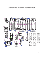
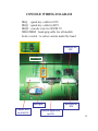
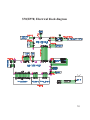
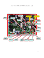
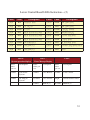
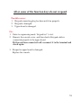
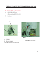
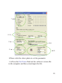
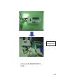
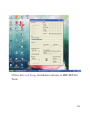
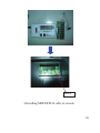
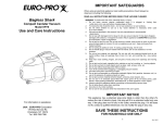
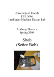
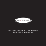
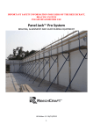
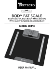
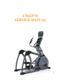
S70(EP78) SERVICE MANUAL 1 TABLE OF CONTENTS SECTION 1: MAINTENANCE PROCEDURE…………….…...3 1. Preventive maintenance tips…………………………..……..…..4 2. Cleaning the grooves………………………………………..........5 SECTION 2: WIRING DIAGRAM INSTRUCTION…...........…6 1. S70 wiring diagram instruction…………………….…………….7 2. Console wiring diagram………………………………………….8 3. Control wire wiring diagram……………………....….…...….….9 4. Incline Motor wire wiring diagram………………...…………….9 5. S70 Electrical block diagram…………………………………….10 6. Lower Control Board LED’s Instruction…………………………11 SECTION 3: CONSOLE ENGINEERING MODE GUIDE…….13 1. Entering and using engineering mode............................................14 2. The List of Manager’s Custom Setting………………………...…15 SECTION 4: TROUBLESHLOOTING…………………………..16 1. Error messages on the console……………………………………17 2. All or some of the function keys do not respond……………...….18 3. Feel slipping while pedaling………………………………………19 4. Knocking or creaking noises…………………………………...…19 5. Heart-Rate-Control function does not work……………...……….20 SECTION 5: SOFTWARE UPGRADE PROCEDURE…………..21 1. Vision S70 bike software upgrade SOP….......................................23 2 SECTION 1 MAINTENANCE PROCEDURE 3 PREVENTATIVE MAINTENANCE TIPS Locate Suspension Elliptical™ Trainer in a cool, dry place. Make sure all bolts and fasteners are kept tight. Keep the display console free from fingerprints and salt build-up caused by sweat. Use a cotton cloth with water and a mild cleaning product to clean the Suspension Elliptical™ Trainer. Other fabrics, including paper towels, may scratch the surface. Do not use ammonia or acid- based cleaners. Clean the exterior of the machine thoroughly on a regular basis. PREVENTATIVE MAINTENANCE SCHEDULE Follow the schedule below to ensure proper operation of the product. ITEM Display console DAILY MONTHLY ANNUALLY CLEAN All bolts and hardware INSPECT Frame CLEAN Handlebars CLEAN Plastic covers CLEAN Footplates BIANNUALLY INSPECT INSPECT 4 CLEANING THE GROOVES Caution: If there is any dust in the grooves of the Poly-V belts and pulleys, noises will be generated during operation. Frequency: Every 3 to 4 months. Procedure: 1.Remove the Poly-V belts and check the grooves of the belt for dirt or dust and clean it if any. 2.Check the grooves in the pulley for dirt or dust and clean it if any. 3.Check the grooves in the roller pulley for dirt or dust and clean it if any 5 SECTION 2 WIRING DIAGRAM INSTRUCTION 6 S70 WIRING DIAGRAM INSTRUCTION 7 CONSOLE WIRING DIAGRAM JKQ : quick key cable for S70 JKQ1 : quick key cable for R70 JKQ2 : console wire for X/U/R 70 JHG1/JHG2 : hand grip cable for all models Select switch : to select current model by hand Quick key for S70 Select switch Hand grip Console wire for X/U/R 70 Quick key for R70 Console digital wire for S70 8 P06 : Control wire P08 : Incline Motor wire 9 S70(EP78) Electrical block diagram 10 Lower Control Board LEDs Instruction—(1) LED 17 LED 2 INCLINE 1 INCLINE 2 LED 14 LED 12 LED 9 LED 11 LED 8 LED 10 LED 7 LED 1 LED 13 LED 16 LED 3 LED 4,5,6 LED 18 LED 15 11 Lower Control Board LEDs Instruction—(2) LED# Color ˟˘˗˄ Red ˟˘˗˅ Red ˟˘˗ˆ Green ˟˘˗ˇ Descriptions LED# Color ˚˸́˸̅˴̇̂̅ʳʳ˥ˣˠ ˟˘˗˄˃ Green ˜ˡ˖˟˜ˡ˘ʳ˄ʳ˷̂̊́ ˔˖ʳˣ˿̈˺ʳ˜ˡ ˟˘˗˄˄ Red ˜ˡ˖˟˜ˡ˘ʳ˅ʳ˷̂̊́ ˩˶˶ʻˈ˩ʼ ˟˘˗˄˅ Yellow ˖˻˴̅˺˼́˺ʳʳʻˣ˪ˠʼ Red ˦̇˴̇̈̆ʳ˼́˷˼˶˴̇̂̅ʳʻ̅˸˹ˁʳˡ̂̇˸ʼ ˟˘˗˄ˆ Red ˇ˃˛˥ˀ˷˼̆˶˻˴̅˺˼́˺ ˟˘˗ˈ Red ˦̇˴̇̈̆ʳ˼́˷˼˶˴̇̂̅ʳʻ̅˸˹ˁʳˡ̂̇˸ʼ ˟˘˗˄ˇ Green ˄˅˩˂ˉ˔ˀ̀˴˼́ʳ̃̂̊˸̅ ˟˘˗ˉ Red ˦̇˴̇̈̆ʳ˼́˷˼˶˴̇̂̅ʳʻ̅˸˹ˁʳˡ̂̇˸ʼ ˟˘˗˄ˈ Green ˖̂́̆̂˿˸ʳ̃̂̊˸̅ʳ ˟˘˗ˊ Yellow ˣ˪ˠˀ˥˸̆˼̆̇˴́˶˸ ˟˘˗˄ˉ Red ˟˘˗ˋ Green ˜ˡ˖˟˜ˡ˘ʳ˄ʳ̈̃ ˟˘˗˄ˊ Green ˟˘˗ˌ Red ˜ˡ˖˟˜ˡ˘ʳ˅ʳ̈̃ ˟˘˗˄ˋ Red LED 4 : (System operation display) LED 5 : Error Message Display Descriptions ˘˲˥ˣˠˀ˘̋̇̅˴ʳ̃̂̊˸̅ʳ ˄ˈ˩˂ˋ˔ˀ˖˻˴̅˺˸ʳ̃̂̊˸̅ʳ̆̂̈̅˶˸ʳ ˙˔ˡ LED 6 Pulse times per sec. Description Pulse times per sec. Description Pulse times per sec. Description 2 times Self-Power System 2 times Class B Error 2 times Class C Error 1 times AC Plug-in System 0.5 times Class A Error bright NO Resistance Offset 1 times Burn-in (1) 0.5 time Burn-in (1) 12 SECTION 3 CONSOLE ENGINEERING MODE GUIDE 13 ENTERING AND USING ENGINEERING MODE Press and hold the UP ϧ and DOWN ϰ of RESISTANCE ARROW keys simultaneously for three seconds. 2. The console will beep and bring you into engineering mode. Use the UP ϧ or DOWN ϰ of RESISTANCE ARROW keys to scroll through the various engineering options. 1. 3. Press the ENTER key to select the appropriate engineering option. 4. Use the UP ϧ or DOWN ϰ RESISTANCE ARROW keys within each setting to modify the setting 5. Press and hold the ENTER key to save the setting. 6. To exit engineering mode, press and hold the START key for three seconds. KEY NAME POSITION FUNCTION UP Select function or adjust value DOWN Select function or adjust value ENTER Enter the function item Hold “ENTER” key 3’s To Save the change Hold “ START” key 3’s To back out of sub menu or exit to main menu Hold RESISTANCE “ UP&DOWN” key 3’s To enter engineering mode Hold RESISTANCE “ UP&DOWN” key 3’s On the “VERSION” System Parameter RESET Hold RESISTANCE “ UP&DOWN” key 3’s On the “AC TIME” or “AC DIST” To clear the AC Time or AC Distance Hold ENTER key 3's On “Incline Cal” Incline Calibration 14 THE LIST OF MANAGER’S CUSTOM SETTING CUSTOM SETTING DEFAULT MINIMUM MAXIMUM DESCRIPTION MAX TIME 99 min 5 min 99 min Set a maximum workout time USER TIME 60 min 5 min 99 min Set a default workout time DF AGE 40 10 100 Set a default age for all programs DF WEIGHT 80kg /150lbs 40kg /80lbs 182kg /400lbs Set a default user weight for all programs DF LEVEL 1 1 20 Set a default resistance level for all programs DF GENDER MALE FEMALE MALE Set a default gender for all programs UNIT MILE KM MILE Set the unit to miles or kilometers MACHINE EP Ё Ё Set machine to bike or elliptical mode AC TIME 0 0 999999 hr Accumulate time AC Distance 0 0 999999 mile Accumulate distance DISPLAY TEST Ё Ё Ё Used by service technicians to test LED displays MACHINE TEST Ё Ё Ё For factory setting only KEYPAD TEST Ё Ё Ё For keypad test VERSION Ё Ё Ё Display Current software version LANGUAGE English The native language prompts in the instruction center INCLINE CAL INCLINE HOMING Incline calibration ON OFF ON On/off incline automation reset to zero position 15 SECTION 4 TROUBLESHOOTINGS 16 Error Messages on the Console Code Class Description Solution B When UCB implements a Incline command, Incline is no action for 3 seconds. Replace incline motor B When the difference of the incline position is over and the difference is not reduction to 3% for 3 seconds. Auto calibration or replace incline motors B When UCB implements a command, LCB has no this command. Upgrade new LCB software C Incline calibration error. When calibration time is too long or calibration distance is too short Replace Incline motor Replace Incline motors C Incline is short circuit(7A) or that the current is over 5A for 1 second. 0x01AC C Power resistor is short circuit (over 4A), or the current is over 3.7A for 1 second . Check the connection of power resistor or replace power resistor 0x02AB C Machine Type Error Setting to correct type of LCB 0x02B3 C Resistance Type Error Setting to correct type of LCB 0x04A0 C If LCB have no message to return UCB over 3 seconds. Replace LCB or UCB or check the communication cable disconnection 0x0201 A LCB Battery Low Voltage Check battery recharge function or replace new battery 0x0248 B Battery disconnection or fail. Check the connection of battery or replace new battery 0x01A0 C Incline Motor no connection Check the connection of incline motor or replace incline motor 0x0140 0x0142 0x0441 0x01A1 0x01A7 17 All or some of the function keys do not respond Possible causes: 1. Keypad connecting plug has been not fit-in properly. 2. Keypad is damaged. 3. Upper board is damaged. Fix: 1. Enter to engineering mode “keypad test” to test. 2. Remove the console cover, and then check if keypad cable is connected properly to the upper board. If it has not been connected well, reconnect it to the terminal and check again. 3. Keypad or upper board is damaged. Replace the console. 18 Feel slipping while pedaling Possible causes: 1. Belt tension is not enough. 2. One way bearing is damaged. Fix: 1. Remove all of the cover. 2. Pedaling and check if the belt tension is correctly. 3. One way bearing is damaged. Replace it with a new one. Knocking or creaking noises Possible causes: 1. Pedal is on crank arm too loose 2. Crank or axle is wear out 3. Belt tension is too loose or poly v belt is too dirty Fix: 1. Re-tighten it. 2. Replace it with a new one 3. Re-adjust the belt tension and clean the poly v belt 19 Heart-Rate-Control function does not work Possible causes: 1. Bike does not contact with user's chest very well. 2. Bike (Polar-belt) is at low battery status. 3. Bike (Polar-belt) is damaged. 4. Heart-rate-control board is damaged. 5. PCB is damaged. Fix: 1. Center the bike on your chest below the pectoral muscle(breast) as shown, then check again. 2. Remove the battery cover of the bike. Replace a new battery and check again. Actually, as moisture may activate the transmitter, please dry transmitter after use. 3. Transmitter is damaged. Replace the Transmitter. 4. Heart-rate-control board is damaged. Replace the HR-control board. 5. PCB is damaged. Replace the PCB. 20 SECTION 5 SOFTWARE UPGRADE PROCEDURE 21 VISION S70 BIKE SOFTWARE UPGRADE SOP A. Service Tools & Accessories: 1. MSP-FET430 Tools (Parts number MTOOL-039) 2. Software A B A : 14 pin B : Power supply specification:8~15V 300mA MSP-FET430 Tools 22 1 2 3 6 4 5 1.Please refer the above photo to set the parameter. 1-6 Press the File Name Find out the software version file in the computer and then actuate/open the file. 23 Computer 2. Install the MSP-FET430 Tools 24 3.Press the Load Image, Installation software to MSP-FET430 Tools. 25 MSP430 4.Installing MSP-FET430 cable to console. 26 5. Press the MSP-FET430 “START” key, the “MODE” light will to glitter about 10 sec, If installing pass, the OK LET light. 6. Drive the machine to provide power for console and then enter into the engineering mode to confirm if the software had been installed/upgraded 27