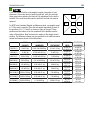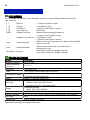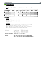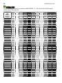
1
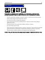
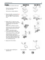
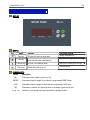
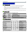
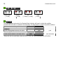
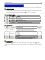
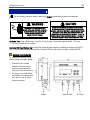
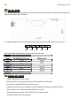
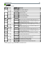
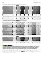
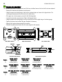
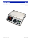
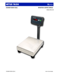
STANDARD BENCH SCALE
OPERATION & SERVICE MANUAL
Models XMC/XWS/XWT (-S) -XIS
STANDARD BENCH SCALE
www.mt.com/xpress
STANDARD BENCH SCALE
2
ABOUT THIS MANUAL AND MT EXPRESS
Thank you for purchasing an MT Xpress product.
All of our equipment is assembled and packed with great care. If you should find any incorrect item, please
contact your Xpress dealer immediately.
MT Xpress products are Weights & Measures approved precision weighing instruments. However, you may
want to obtain official certification through your supplier or local Weights & Measures office.
This MT Xpress product was developed, produced, and tested in a METTLER TOLEDO facility that has been
audited and registered according to international ISO 9001 quality standards and ISO 14000 environment
control program. Properly used and maintained, this product will provide years of accurate weighing.
Handle it as you would any piece of fine electronic equipment.
Please READ this manual BEFORE operating or servicing this equipment. Follow the instructions carefully
and save this manual for future reference.
We at MT Xpress want to make sure you received the product you expected. It is important to us that you
are satisfied with your purchase. If there is anything we can help you with, or if you are not satisfied with
either your product or the services received from the Xpress representative, let us know.
How can you reach us?
XPRESS CUSTOMER CARE CENTER, USA
24/7 Information and Support:
www.mt.com/xpress
[email protected]
8 AM to 8 PM EST
Toll Free: 1-866-MTXPRESS
Xpress
Mettler-Toledo, Inc.
60 Collegeview
Westerville, OH 43081
STANDARD BENCH SCALE
3
FCC Approval
This device complies with part 15 of the FCC Rules. Operation is subject to the following two
conditions: (1) this device may not cause harmful interference, and (2) this device must accept
any interference received, including interference that may cause undesired operation.
4
STANDARD BENCH SCALE
CONTENTS
SAFETY NOTICE ...........................................................................................................................................5
PREPARING THE SCALE FOR USE ...................................................................................................................6
ENVIRONMENT................................................................................................................................... 6
UNPACKING AND ASSEMBLY ............................................................................................................... 6
POWER UP/DOWN SEQUENCE............................................................................................................. 8
YOUR XPRESS SCALE AT A GLANCE ................................................................................................................9
DISPLAY ............................................................................................................................................ 9
KEYPAD ............................................................................................................................................ 9
CURSORS (LED)................................................................................................................................. 9
OPERATING YOUR SCALE ............................................................................................................................10
STRAIGHT WEIGHING........................................................................................................................ 10
RE-ZERO FUNCTION.......................................................................................................................... 10
TARE FUNCTION ............................................................................................................................... 10
SPECIAL MODES - OVER/UNDER ..................................................................................................................11
OVER/UNDER SETUP MODE ............................................................................................................... 11
FUNCTION OF THE KEYS.................................................................................................................... 11
SET OVER AND UNDER VALUES.......................................................................................................... 11
OVER AND UNDER CURSORS ............................................................................................................. 12
OPERATION ..................................................................................................................................... 12
SCALE SOFTWARE SETUP............................................................................................................................13
ACCESS TO SETUP MODE .................................................................................................................. 13
FUNCTION OF THE KEYS.................................................................................................................... 13
PARAMETER LIST.............................................................................................................................. 13
EXIT SETUP MODE ............................................................................................................................ 13
CLEANING & MAINTAINING YOUR SCALE .......................................................................................................14
CLEANING AND MAINTENANCE .......................................................................................................... 14
TROUBLESHOOTING.......................................................................................................................... 14
SERVICING YOUR INDICATOR.......................................................................................................................15
VOLTAGE CHECKS ............................................................................................................................ 15
OPENING THE INDICATOR ................................................................................................................. 15
LOAD CELL WIRING .......................................................................................................................... 16
KEYBOARD REPLACEMENT ................................................................................................................ 16
CONTROLLER PCB REPLACEMENT...................................................................................................... 17
ACCESSING THE SERVICE MODE ........................................................................................................ 17
FUNCTION OF THE KEYS.................................................................................................................... 17
PARAMETER LIST.............................................................................................................................. 18
CALIBRATION ................................................................................................................................... 19
GRAVITY ADJUSTMENT...................................................................................................................... 20
SERVICING YOUR SCALE BASE .....................................................................................................................21
LOAD CELL REPLACEMENT ................................................................................................................ 21
OVERLOAD STOP ADJUSTMENT.......................................................................................................... 22
SHIFT TEST ...................................................................................................................................... 23
APPENDIX.................................................................................................................................................24
ERROR MESSAGES ........................................................................................................................... 24
INDICATOR SPECIFICATIONS .............................................................................................................. 24
BASE SPECIFICATIONS ...................................................................................................................... 25
GEO VALUE TABLE ............................................................................................................................ 26
PHYSICAL DIMENSIONS..................................................................................................................... 27
STANDARD BENCH SCALE
5
SAFETY NOTICE
Product safety is a fundamental concern at MT Xpress. Use common sense and follow the simple
precautions listed below to ensure your safety and optimize the use and performance of this product.
− Read this manual before operating or servicing this product. Save this manual for future reference.
− Observe safety warnings located throughout this manual.
− Use caution when lifting or moving heavy equipment.
− This product should be serviced by qualified personnel. Exercise care when moving, testing, or
adjusting this product.
− Disconnect all power to this product before installing, servicing, or cleaning.
− Use only MT Xpress parts for repair.
− Observe electrostatic handling precautions for electronic components. Allow at least 30 seconds after
power disconnection to allow charges to dissipate before servicing any electronic components.
− Allow the product to stabilize at ambient room temperature before applying power.
FAILURE TO FOLLOW THESE PRECAUTIONS COULD RESULT IN DAMAGE TO EQUIPMENT OR BODILY HARM.
STANDARD BENCH SCALE
6
PREPARING THE SCALE FOR USE
Xpress Standard Bench Scales are designed to meet the real world requirements of manufacturing,
agricultural, packaging, and general weighing applications, and are ready to use right out of the box.
The Xpress Standard Indicator is a rugged, reliable electronic weighing indicator in an IP65 washdown
enclosure designed for easy operation in washdown applications. The Xpress Standard Bench stainless
steel platforms (XMC-S, XWS-S and XWT-S) are also manufactured to be used in washdown applications.
Xpress Standard Bench mild steel platforms (XMC, XWS and XWT) are intended for use in general purpose
industrial and commercial environments. For the best performance, they should not be used in
environments requiring washdown, immersion in liquids, or exposure to corrosive chemicals
This chapter gives detailed instructions and important information regarding the successful installation of
the Xpress Standard Bench Scale.
ENVIRONMENT
Before you install the scale, identify the best location for the equipment. The proper environment enhances
its operation and longevity. Keep in mind the following factors, which might have a negative influence on
the scale's operation:
Vibration: Vibration diminishes the scale’s ability to measure accurately. Electrical machinery such as
conveyors and drill presses can cause inaccurate and non-repeatable readings. The scale may also read
inaccurately if it is not leveled properly.
Air currents: Moving air can cause the scale to read wind movement as an additional force and cause
inconsistency in the weighing results.
Friction: A scale cannot measure accurately if an object is rubbing or pressing against the scale platform.
UNPACKING AND ASSEMBLY
Thank you for purchasing an MT Xpress product. Please inspect the package immediately upon receipt. If
the box is damaged, check for internal damage and file a freight claim with the carrier if necessary. If the
container is undamaged, open the box, remove the scale and place it on a solid, flat surface. Please keep
the packing material and shipping insert in case you need to return the scale to an Xpress representative.
Package contents for all Xpress Standard Bench Scales include:
Product
− Xpress Standard Indicator
− Xpress Base
− Column kits
− Accessory bag (seal screws, lead
seal wires, leads, column mounting
screws, flat washers, spring
washers, cable clamp, cable
protective baffle, Allen key)
Documents
− Quick Start Guide
− Installation Instructions
CD-ROM
− Operation & Service Manual
STANDARD BENCH SCALE
Instructions
1. Open the box and take out the scale.
7
Models XWS (-S)
Models XWT (-S)
Remove the packing material from
each side of the scale.
Set the unit on a sturdy workplace.
2. Remove the platter, and remove the red
plastic shipping tabs in the corner of
the scale. (XMC (-S) model skip this
step).
3. Models XWS (-S): Attach the column
bracket beneath the bottom scale frame
by tightening the four socket head
screws.
Models XWT (-S):Attach the column
bracket near to the side of bottom scale
frame by tightening the two hex head
screws.
XMC (-S) model skip this step.
4. Coil the excess load cell cable and
insert it into the column. A small length
of tape applied to the ends of the coils
allows the cable to slide into the
column easier Mount the indicator onto
the column. Adjust the indicator to the
proper angle and fasten the bolt. (XMC
(-S) model skip this step).
5. Apply power to the indicator.
6. Level the scale by adjusting four
adjustable feet.
Proper alignment
Improper alignment
STANDARD BENCH SCALE
8
POWER UP/DOWN SEQUENCE
Power Up: Press the power key
to turn on the Xpress XIS. It goes through a series of self-tests when it is
turned on. The scale performs diagnostics on its internal memory, and precedes to normal the operating
mode. The power up sequence is as follows:
z
All segments of the display segments and cursors light to verify operation.
z
Next the unit displays the software part number; revision number, geo value and country one by one.
z
The unit captures zero and is ready for normal operation.
Note: Before switching on the scale, always make sure there is nothing on the platter. If you have powered
up the unit with something on the scale, the scale may not find the zero value, and shows “------“. To clear
this condition remove the item, press the power key until the unit displays “off”, then press the power key
again, the scale will then capture the correct zero value.
Power Down: Press the power key
until “OFF” is shown on the display to turn off the scale.
STANDARD BENCH SCALE
9
YOUR XPRESS SCALE AT A GLANCE
DISPLAY
KEYPAD
Key
Name
Function
Over/Under Setting
Setting complete exit
Zero key
To return the scale to gross zero.
Tare key
To tare the scale. Pressing this key at zero
clears the tare value from memory.
Increment one digit (up 1, 2, 3..)
To enter OVER/UNDER mode.
Move to the next digit to the right
To turn the scale on or off.
Confirm choice
Function key
Power key
CURSORS (LED)
Cursor
>0<
Description
Illuminates when weight is gross zero (0).
UNDER
Illuminates when the weight is less than the programmed UNDER value
OVER
Illuminates when the weight is more than the programmed OVER value.
Net
lb, kg, oz
Illuminates to indicate the displayed value is net weight (gross minus tare).
Indicates current weight unit associated with the displayed value.
STANDARD BENCH SCALE
10
OPERATING YOUR SCALE
STRAIGHT WEIGHING
− Place the item to be weighed on the platter.
− Remove the item from the platter and the display will return to 0.000.
RE-ZERO FUNCTION
There are two ways to re-zero the scale:
− Power-up Zero: The scale will automatically capture zero when it is turned on. The power-up zero
capture range is +/-10% of the scale capacity.
Note: When the scale is turned on with a weight on the platter is more than 10% of the capacity, the
scale will not capture zero (the weight display will show "-----") to indicate that the scale will not be
ready for use. After removing the weight the scale will capture "zero".
The ZERO key sets the gross zero value over a range of +/-2% of the scale
− Push-button Zero:
capacity. To use this function, the scale must be in the gross weighing mode (NET cursor dark) and
in a no-motion condition. When the weight on the platter is more then +/-2% of the scale capacity
depressing the zero key will not yield a result until the weight is removed and the Zero key has been
depressed a second time.
TARE FUNCTION
The
key subtracts the weight of the container or wrapping material placed on the scale prior to
weighing a desired item.
− Place the empty container or wrapping material on the platter, e.g. 5 lb.
− Press the
key, it show net weight 0 lb, the net weight cursor should light.
− Place the item to be weighed onto the platter or into the container or wrapping material.
− Note the net weight value and record it if necessary.
− Remove the weighed and container or wrapping material from the platter, the display will show the
negative net weight of the container, e.g. -5 lb. This indicates the net weight of the container.
key to return the scale back to gross weighing mode, proper execution of this function is
− Press
indicated when the net cursor is not illuminated.
STANDARD BENCH SCALE
11
SPECIAL MODES - OVER/UNDER
OVER/UNDER SETUP MODE
Press
key to access to over under zone setup mode. The display will show the default 0.000.
− The digits on the both sides of the decimal point vary with the capacity and resolution.
− Over/Under values will reset to zero if you change the scale’s resolution.
− The Standard Bench Indicator will only permit over under values conforming to the minimum resolution
of the scale.
− The Over cursor will light to select the “Over” value, and the Under will light to select the ‘Under’ value.
FUNCTION OF THE KEYS
In Over/Under Setup Mode, the functions of the keys will be as follows:
Key
Function
Start, then
Increment digit
Description
Choose Over/Under Setup
Increment the flashing digit one right.
Increment
Increase the value in selected digit.
Confirm choice
Confirm the choice and step forward
End setup
End Setup mode and return the scale to weighing mode.
SET OVER AND UNDER VALUES
Example: 5 lb scale, the Over Value is 0.506 lb, Under Value is 0.4 lb:
The Procedure
Display
Cursor
Action
Press
to access to Setup mode
[ 0.000]
OVER
Enable setup
Press
1 time
[ 0.000]
OVER
Increment digit right
Press
5 times
[ 0.500]
OVER
Increase digit value
Press
twice
[ 0.500]
OVER
Increment to the next digit
Press
6 times
[ 0.506]
OVER
Increase digit value
Press
to proceed
[ 0.000]
UNDER
Select UNDER range
Press
1 time
[ 0.000]
UNDER
Increment digit right
Press
4 times
[ 0.400]
UNDER
Increase digit value
Press
to back to weighing mode
[ 0.000]
Ready to weigh
At zero, both the Over and Under Cursors are dark. At the first increment over zero, the Under cursor will light
up.
STANDARD BENCH SCALE
12
OVER AND UNDER CURSORS
UNDER
OVER
UNDER
OVER
UNDER
OVER
UNDER
OVER
Scale at Zero
UNDER
Ok
OVER
[ 0.000]
[ <0.399]
[ 0.400]Ù[ 0.506]
[ 0.507 <]
OPERATION
When an Over/Under value exists, the Standard Bench Indicator will beep to indicate the condition
provided that the function is enabled in the scale setup. The below table is a matrix of possible conditions:
Setup
Condition
Actual weight greater than the Over value
Actual weight less than the Under value
Actual Weight between Over/Under Limits*
S3 is 1
S3 is 2
Cursor
Beep
Beep
Beep
-
Over
Under
Over and Under
*When both the Over and Under values are set to 0.000, the cursors and beeper do not function.
STANDARD BENCH SCALE
13
SCALE SOFTWARE SETUP
Several parameters in the scale can be changed to enable you to setup the scale to your individual needs.
ACCESS SETUP MODE
− Turn off the scale by pressing the Power key until the display displays “Off”; the display should be dark.
− Press the Power key while continuously pressing the
until “S1 OFF” is displayed.
FUNCTION OF THE KEYS
Key
Name
Function
Finish key
Finish Setup
Toggle key
Chose parameter
Back key
Accept key
Step backwards to last step
Confirm choice and step forwards to next step
PARAMETER LIST
SoftSwitch
S3
Description
Beep range
S4
Filter strength
S5
S6
S7
Weight unit
LED brightness
Display type
Available Parameter
0 = No beep
1 = Beep when weight is between over and under value.
2 = Beep when weigh is out of range of over and under
0 = Light
1 = Normal
2 = Strong
3 = Very strong
lb/kg/oz
0 = Normal. Each additional value yields a dimmer display
Off = Continuous display update; On: quick weight
Default
0
2
lb
0
Off
EXIT SETUP MODE
Press the Finish key
to finish setup. “SAVE” is displayed to save all changes. Press
to toggle
to return the scale to weighing
between “Save” (Save changes) and “Abort” (Abort all changes). Press
mode.
STANDARD BENCH SCALE
14
CLEANING & MAINTAINING YOUR SCALE
WARNING
DISCONNECT ALL POWER TO THIS UNIT
BEFORE INSTALLING, SERVICING,
CLEANING, OR REMOVING THE FUSE.
FAILURE TO DO SO COULD RESULT IN
BODILY HARM AND/OR PROPERTY
DAMAGE.
CLEANING AND MAINTENANCE
− DO NOT allow untrained personnel to operate, clean, inspect, maintain, service, or tamper with this
equipment.
− DO NOT attempt to remove the cover or perform service or maintenance on the internal parts of the
scale.
− ALWAYS DISCONNECT this equipment from the power source before cleaning or performing
maintenance.
− KEEP the scale clean. Periodically clean the keyboard and covers with a soft clean cloth that has been
dampened with a mild window cleaner or detergent. DO NOT USE ANY TYPE OF INDUSTRIAL SOLVENT
OR CHEMICALS. DO NOT SPRAY CLEANER DIRECTLY ONTO THE UNIT.
TROUBLESHOOTING
If operational difficulties are encountered, first obtain as much information as possible regarding the
problem. Failures and malfunctions often may be traced to simple causes such as loose connections or
improper setup.
Additional troubleshooting can be performed for you by an authorized MT Xpress representative.
STANDARD BENCH SCALE
15
SERVICING YOUR INDICATOR
For the following services, please contact your Xpress representative at www.mt.com/xpress.
WARNING
VOLTAGE CHECKS
DISCONNECT ALL POWER TO THIS UNIT
BEFORE INSTALLING, SERVICING, CLEANING,
OR REMOVING THE FUSE. FAILURE TO DO
SO COULD RESULT IN BODILY HARM
AND/OR PROPERTY DAMAGE.
CAUTION
BEFORE CONNECTING OR DISCONNECTING ANY INTERNAL
ELECTRONIC COMPONENTS OR INTERCONNECTING WIRING
BETWEEN ELECTRONIC EQUIPMENT, ALWAYS REMOVE POWER
AND WAIT AT LEAST THIRTY (30) SECONDS BEFORE ANY
CONNECTIONS OR DISCONNECTION’S ARE MADE. FAILURE TO
OBSERVE THESE PRECAUTIONS COULD RESULT IN DAMAGE TO
OR DESTRUCTION OF THE EQUIPMENT, OR BODILY HARM.
AC Power Test: Using a Multi-meter, check the AC input power. Input power must be within -15% and
+10% of the nominal AC line voltage.
Controller PCB Input Voltage Test: Confirm the universal power supply is outputting a voltage of at least 12
VDC. If the XIS indicator has power and the Controller PCB does not function properly, replace the PCB.
OPENING THE INDICATOR
To access the Controller PCB for
internal wiring and switch setting:
1. Unscrew the four screws
located on the each side of
enclosure and separate the
front panel from the enclosure.
2. The figure on the right shows
the location of the screws and
the Load Cell and AC power
cable connections.
Screws
Loadcell Cable
AC Power
STANDARD BENCH SCALE
16
LOAD CELL WIRING
After opening the XIS terminal enclosure, the main circuit board is mounted on the front panel. Refer to the
figure for the detail cable connection:
The following diagrams show the load cell terminal strip wiring for the XIS terminal on connector J-1.
GND
-EXE
-SIG
+SIG
+EXE
Refer to the below information for the load cell cable color code:
Signal
+EXC
+SEN
+SIG
CGND
-SIG
-SEN
-EXC
Load cell color code for
MT1022/SSP1022 series
GREEN
RED
WHITE
BLACK
Load cell color code for
MT/SSP series
GREEN
BLUE
RED
YELLOW
WHITE
BROWN
BLACK
KEYBOARD REPLACEMENT
− Disconnecting the AC power adapter.
− Remove the four screws securing the front and back portions of the cover.
− Unscrew the controller PCB from the old front cover.
− Replace the new front cover assembly (including keyboard) and secure controller PCB on it.
− Secure the front cover to the back cover with the four screws.
− Apply power then press and hold the ON/OFF key for three seconds.
− Test the operation of the new keyboard.
STANDARD BENCH SCALE
17
CONTROLLER PCB REPLACEMENT
If the Controller PCB is suspected to be faulty, use the following procedure to replace the PCB.
− Disconnecting the AC power.
− Remove the four screws securing the front and back halves of the cover.
− Disconnect the power harness from the Controller PCB and set the front cover aside.
− Remove the four screws that secure the Controller PCB to the front cover.
− Using proper static electricity precautions carefully remove the Controller PCB and place it in a protective
static bag.
− Install the new Controller PCB using the same four screws removed in the previous step.
− Reconnect the AC adapter harnesses removed previously.
− Secure the front cover to the back cover with the four screws.
− Apply power to the XIS indicator then press and hold the ON/OFF key for three seconds.
− Reprogram, recalibrate, and test the operation of the new Controller PCB.
ACCESSING THE SERVICE MODE
The Service Mode allows an authorized Xpress representative to access the Service Mode switches in the
software setup.
Open the terminal enclosure by unscrewing the four Phillips screws. Shorten the two pins of K5 on the
main board. The display will show “SETUP” for a short time, and then show “DEF NO”. This means the
scale has accessed the Service Mode.
FUNCTION OF THE KEYS
Key
Name
Function
Finish key
Finish Setup
Toggle key
Chose parameter
Back key
Accept key
Steps backward to last (previous) step
Confirm choice and move forwards to next step
STANDARD BENCH SCALE
18
PARAMETER LIST
Soft-Switch
Description
Def
Initiate default
S3
Beep range
Available Parameter
No = Don’t initiate the default
Yes = Initiate the default
0 = No beep
1 = Beep when weight is between over and under value
2 = Beep when weigh is out of range of over and under
Default
No
0
S4
Filter strength
0 = Light
1 = Normal
2 = Strong
3 = Very strong
S5
Weight unit
lb/kg/oz
lb
S6
LED brightness
0 = Normal. Each additional value yields a dimmer display
0
S7
Display type
Off = Continuous display update
On = Quick weight
Off
S8
Resolution
On = 10000 / 12500 (for oz is 8000)
0ff = 5000 (for oz is 4000)
Off
S9
Access to S8 in
setup mode
On = Enable
Off = Disable
Off
S10
Expanded display
On = Expanded display (50,000 quantity)
Off = Normal display
Off
GEO
GEO
0 to 31
12
Cal
Calibrate
YES = Calibrate scale
NO = Don’t calibrate scale
No
2
STANDARD BENCH SCALE
19
CALIBRATION
Example using a 50 lb scale:
Step
Operation
Display
Press
[CAL
[
YES]
lb] Default calibration weight unit
Press
[
kg] Choose suitable parameter
Press
[
Press
[
50] Choose suitable parameter
Press
[Lin
NO] Choose non-linearity calibration
Press
[Lin yes] Choose linearity calibration
3.1
3.1.1
If choice NO
Press
[------]
3.1.2
Press
[
1
2
3
Description
5] Capacity of the scale
5]
[LD
25]
Press
[LD
30]
3.1.4
Press
[
3.2
3.2.1
If choice YES
Press
[------]
3.2.2
Press
[
5]
[
30]
[
5]
[
50]
[
5]
[
save]
3.1.3
3.2.3
3.2.4
Press
3.2.5
3.2.6
4
5
Press
5]
Capture zero, make sure the platter is empty before press [>0<]
The scale count down from 5 to 0, if the scale isn’t stable, it will
count again until find stable zero.
Put the weight of 25 lb (1/2 of the full capacity) on the platter
Choose the suitable weight value you prefer, can be 1/2, 3/5 or full
capacity
The scale count down from 5 to 0, if the scale isn’t stable, it will
count again until find stable zero.
Capture zero, make sure the platter is empty before press [>0<]
The scale count down from 5 to 0, if the scale isn’t stable, it will
count again until find stable zero.
Put the weight of 30 lb (3/5 of the full capacity) on the platter
The scale count down from 5 to 0, if the scale isn’t stable, it will
count again until find stable zero.
Put the weight of 50 lb (full capacity) on the platter
Capture span. The scale count down from 5 to 0, if the scale isn’t
stable, it will count again until find stable zero.
Save calibration and all setting changes
Press
[ abort]
Abort calibration and all setting changes
Press
[
Finish calibration and enter into Weight Display Mode
0.00]
The lines highlighted in gray are for reference of parameter choice.
STANDARD BENCH SCALE
20
The available capacities calibrated in pounds (lb) are as follows:
Capacity (lb)
5
10
25
Normal Resolution
5000
5000
5000
Increment size (lb)
0.001
0.002
0.005
High Resolution
10,000
10,000
12,500
Increment size (lb)
0.0005
0.001
0.002
Required added weight when choosing non-linearity calibration
1/2 FS (lb)
5
3/5 FS (lb)
3
6
15
FS (lb)
5
10
25
Required added weight when choosing linearity calibration
First point (3/5 FS)
3
6
15
Second point (FS)
5
10
25
50
5000
0.01
10,000
0.005
100
5000
0.02
10,000
0.01
250
5000
0.05
12,500
0.02
500
5000
0.1
10,000
0.05
25
30
50
50
60
100
125
150
250
250
300
500
30
50
60
100
150
250
300
500
25
5000
0.005
12,500
0.002
50
5000
0.01
10,000
0.005
100
5000
0.02
10,000
0.01
250
5000
0.05
12,500
0.02
15
25
25
30
50
50
60
100
125
150
250
15
25
30
50
60
100
150
250
800
4000
0.2
8000
0.1
1600
4000
0.5
8000
0.2
4000
4000
1
8000
0.5
8000
4000
2
8000
1
The available capacities calibrated in kilograms (kg) are as follows:
Capacity (kg)
2.5
5
10
Normal Resolution
5000
5000
5000
Increment size (kg)
0.0005
0.001
0.002
High Resolution
12,500
10,000
10,000
Increment size (kg)
0.0002
0.0005
0.001
Required added weight when choosing non-linearity calibration
1/2 FS (kg)
5
3/5 FS (kg)
1.5
3
6
FS (kg)
2.5
5
10
Required added weight when choosing linearity calibration
First point (3/5 FS)
1.5
3
6
Second point (FS)
2.5
5
10
The available capacities displayed in ounces (oz) are as follows:
Capacity (oz)
Normal Resolution
Increment size (oz)
High Resolution
Increment size (oz)
80
4000
0.02
8000
0.01
160
4000
0.05
8000
0.02
400
4000
0.1
8000
0.05
GRAVITY ADJUSTMENT
The Standard Indicator has built in compensation provisions to allow factory calibration with destination
correction capabilities to compensate for variances on gravitational forces. If the Standard Indicator is
subjected to a different gravitational force at its destination location, this can be compensated for
electronically by adjusting the geo value. The geo value has 32 settings. The geo value for any world
location can be found in the Geo Value Table in the Appendix as long as the geographical coordinates and
elevation above sea level are known.
STANDARD BENCH SCALE
21
SERVICING YOUR SCALE BASE
For the following services, please contact your Xpress representative at www.mt.com/xpress.
CAUTION
WARNING
DISCONNECT ALL POWER TO THIS UNIT BEFORE
INSTALLING, SERVICING, CLEANING, OR
REMOVING THE FUSE. FAILURE TO DO SO
COULD RESULT IN BODILY HARM AND/OR
PROPERTY DAMAGE.
−
−
−
−
−
−
−
−
−
BEFORE CONNECTING OR DISCONNECTING ANY INTERNAL
ELECTRONIC COMPONENTS OR INTERCONNECTING
WIRING BETWEEN ELECTRONIC EQUIPMENT, ALWAYS
REMOVE POWER AND WAIT AT LEAST THIRTY (30)
SECONDS. FAILURE TO OBSERVE THESE PRECAUTIONS
COULD RESULT IN DAMAGE TO OR DESTRUCTION OF THE
EQUIPMENT, OR BODILY HARM.
LOAD CELL REPLACEMENT
Disconnect the power.
Remove the stainless steel platform from the base.
Loosen and remove the top load cell mounting bolts that secure the top frame to the load cell.
Set the top frame and the load cell spacer aside.
Turn the scale on its side to access the bottom load cell bolts.
Loosen and remove the bottom load cell mounting bolts.
Remove the load cell from the base and pull the excess cable out through the bottom of the column.
Reinstall a new load cell by following the steps above in reverse order.
Note: Lubricate the threads and under the head of the load cell mounting bolts before reinstalling.
Using a torque wrench, tighten the load cell mounting bolts to the specifications shown in this table:
Base Model
XMC03, XMC03S
XMC06, XMC06S
XMC15, XMC15S
XWS30R, XWS30RS
XWS60R, XWS60RS
XWS60M, XWS60MS
XWS150M, XWS150MS
XWT150M, XWT150MS
XWT300M, XWT300MS
Metric
10 N•m
10 N•m
10 N•m
10 N•m
10 N•m
10 N•m
15 N•m
25 N•m
30 N•m
English
7.5 ft/lb
7.5 ft/lb
7.5 ft/lb
7.5 ft/lb
7.5 ft/lb
7.5 ft/lb
11 ft/lb
18 ft/lb
22 ft/lb
− After replacing a load cell, the overload stops must be checked and adjusted (if needed). Refer to the
next section for the overload stop adjustment procedure.
− Thread the load cell cable through the column from the bottom.
− Connect load cell cable to terminal.
− Coil the excess load cell cable and insert it into the column. A small length of tape applied to the ends
of the coils allows the cable to slide into the column easier.
− Apply power to the scale.
− Recalibrate and test the operation of the new load cell.
STANDARD BENCH SCALE
22
OVERLOAD STOP ADJUSTMENT
The overload stops must be checked and reset if the top or bottom frame or the load cell has been replaced.
− Remove the stainless steel platform from the base.
− Using the proper size feeler gauge, check all six overload stops as shown in the figure below. The
correct gap measurements can be found in the table below.
− If the gaps are not set properly, proceed to the following steps.
− Loosen the overload screw jam nuts. Refer to the figures below.
− Using the proper size feeler gauge, turn the screw until you feel a slight drag on the feeler gauge.
− Tighten the jam nut and recheck the gap. Readjust if necessary.
− Adjust all six overload stops using this procedure.
− Reinstall the platform and make sure the scale weighs to full capacity.
A
B
B
A
A
A
A
A
B
A
B
B
A
A
A
A
A
XMC, XMC-S models
Set screw
XWS, XWS-S models
XWT, XWT-S model
Jam nut
Gap B
Gap A
Gap
Overload stop
Overload screw jam nuts
Gap measurement points
Position
A
B
XMC03, XMC03S
Overload Gap
1 mm (0.04 in.)
0.5 mm (0.02 in.)
XMC06, XMC06S
Overload Gap
1 mm (0.04 in.)
0.5 mm (0.02 in.)
XMC15, XMC15S
Overload Gap
1.5 mm (0.06 in.)
0.5 mm (0.02 in.)
Position
A
B
XWS30R, XWS30RS
Overload Gap
2 mm (0.078 in.)
0.5 mm (0.02 in.)
XWS60R, XWS60RS
Overload Gap
2 mm (0.078 in.)
0.5 mm (0.02 in.)
XWS60M, XWS60MS
Overload Gap
3 mm (0.118 in.)
0.75 mm (0.03 in.)
Position
A
B
XWT150M, XWT150MS
Overload Gap
4 mm (0.157 in.)
1 mm (0.04 in.)
XWT300M, XWT300MS
Overload Gap
6 mm (0.236 in.)
1 mm (0.04 in.)
XWS150M, XWS150MS
Overload Gap
3 mm (0.118 in.)
0.75 mm (0.03 in.)
STANDARD BENCH SCALE
23
SHIFT TEST
A shift test verifies that the scale weighs correctly irrespective of load
placement. If the scale does not pass the shift test, verify the overload
stops gaps before replacing the load cell. No adjustment for the shift is
possible. If the scale does not pass the shift test, the load cell must be
replaced.
A
D
For NTEP and Canadian Weights and Measures tests, use weights equal
to 1/2 the scale’s capacity. Place the test weight sequentially at each of
the positions A, B, C, D and E as shown in figure in the right. These
positions are the centers of the four quadrants of the platform and the
center of the platform. Note the terminal’s reading of the weight at each
position. The difference between any two positions in the shift test cannot
exceed the tolerance shown in the table below.
SCALE
CAPACITY
DISPLAY
INCREMENT
USA and CANADA
TEST WEIGHT
XMC03(S)
5 lb/2.5 kg
0.001 lb/0.0005 kg
2.5 lb/1.25 kg
XMC06(S)
10 lb/5 kg
0.002 lb/0.001 kg
5 lb/2.5 kg
XMC15(S)
25 lb/10 kg
0.005 lb/0.002 kg
12.5 lb/5 kg
XWS30R(S)
50 lb/25 kg
0.01 lb/0.005 kg
25 lb/12.5 kg
XWS60R(S)
100 lb/50 kg
0.02 lb/0.01 kg
50 lb/25 kg
XWS60M(S)
100 lb/50 kg
0.02 lb/0.01 kg
50 lb/25 kg
XWS150M(S)
250 lb/100 kg
0.05 lb/0.02 kg
125 lb/50 kg
XWT150M(S)
250 lb/100 kg
0.05 lb/0.02 kg
125 lb/50 kg
XWT300M(S)
500 lb/250 kg
0.1 lb/0.05 kg
250 lb/125 kg
E
B
C
TOLERANCE
(NEW)
±0.001 lb
±0.0005 kg
±0.002 lb
±0.001 kg
±0.005 lb
±0.002 kg
±0.01 lb
±0.005 kg
±0.02 lb
±0.01 kg
±0.02 lb
±0.01 kg
±0.05 lb
±0.02 kg
±0.05 lb
±0.02 kg
±0.1 lb
±0.05 kg
TOLERANCE
(IN SERVICE)
±0.002 lb
±0.001 kg
±0.004 lb
±0.002 kg
±0.01 lb
±0.004 kg
±0.02 lb
±0.01 kg
±0.04 lb
±0.02 kg
±0.04 lb
±0.02 kg
±0.1 lb
±0.04 kg
±0.2 lb
±0.04 kg
±0.2 lb
±0.1 kg
STANDARD BENCH SCALE
24
APPENDIX
ERROR MESSAGES
The XIS indicator will display an error message if a problem or incorrect keyboard entry is sensed. The
error codes are:
E 11
E 16
E 18
E 48
ERROR
RAM error
ROM error
EEPROM error
Alarm setup error
Software running error
------
Unsteadily or can’t find zero
nnnnn
Overload indication
uuuuu
Underload indication
Dark display
No power
1. Power off and power up again.
2. Recalibrate the scale.
3. Replace the main board or load cell.
Review setup.
Restart the scale by pressing the power key.
1. Power-up when the platter is empty.
2. Recalibrate the scale.
3. Replace the main board or load cell.
Weight is more than full capacity plus 9e. Remove items from platter
and re-zero the scale.
Weight on scale is below gross zero by more than 9e.
Increase load on scale.
Check that the transformer is plugged in the wall.
Insure that the transformer is plugged in the scale.
INDICATOR SPECIFICATIONS
Feature
Description
Displayed Resolution
Physical Dimensions
(w x d x h)
Construction
Power
Up to 12,500d
Environmental Protection
Display
Scale Type
Keypad
Operating Temperature
Storage Temperature
Data Output
Weighing Units
8” x 6” x 3”
304 stainless steel
100 to 240VAC universal power supply, 50 to 60Hz
Equal to IP65
The indicator is NOT intrinsically safe!
6 digits, 12 mm height, bright red LED
Analog:
Suitable for 2mV/V and 3mV/V load cells
Can power up to one (1) 350 ohm load cells
4 membrane keyboard:
ON/OFF, ZERO, TARE, FUNCTION
14°F to 104°F (-10°C to 40°C) with10 to 95% relative humidity, non-condensing
–4°F to 140°F (-20°C to 60°C) with 10 to 95% relative humidity, non-condensing
None
pounds, kilograms, and ounce
Specifications are subject to change without notice.
STANDARD BENCH SCALE
25
BASE SPECIFICATIONS
Base size
Xpress Standard Bench Scales are available in four sizes with seven capacities:
Size/Capacity
9” x 9”
12” x 14”
16” x 20”
20” x 28”
5 lb
X
10 lb
X
25 lb
X
50 lb
100 lb
X
X
X
250 lb
500 lb
X
X
X
Construction
Platform
XMC, XMC-S: Fabricated of stainless steel
XWS, XWS-S: Fabricated of stainless steel
XWT, XWT-S: Fabricated of stainless steel
Scale Base
XMC, XWS: Formed and welded mild steel, painted blue, aluminum load cell
XWT: Welded tubular mild steel, painted blue, aluminum load cell
XMC-S, XWS-S: Formed and welded stainless steel, stainless steel load cell
XWT-S: Welded tubular stainless steel, stainless steel load cell
Overloading
Corner loading:
100% of full capacity
Safe Overload:
150% of full capacity
Ultimate Overload: 300% of full capacity
Operating Temperature
10° to 104°F (–10 °C to +40 °C)
Humidity
XMC, XWS and XWT base: 0 to 95% relative humidity
XMC-S, XWS-S and XWT-S base: Washdown applications
STANDARD BENCH SCALE
26
GEO VALUE TABLE
Use the following geo codes if you relocate the XMC/XWS/XWT (-S) -XIS to a site other than the original
location where it was calibrated.
Northern
and
Southern
latitude in
degrees and
minutes
0° 0′ — 5° 46′
5° 46′ — 9° 52′
9° 52′ — 12° 44′
12° 44′ — 15° 6′
15° 6′ — 17° 10′
17° 10′ — 19° 2′
19° 2′ — 20° 45′
20° 45′ — 22° 22′
22° 22′ — 23° 54′
23° 54′ — 25° 21′
25° 21′ — 26° 45′
26° 45′ — 28° 6′
28° 6′ — 29° 25′
29° 25′ — 30° 41′
30° 41′ — 31° 56′
31° 56′ — 33° 9′
33° 9′ — 34° 21′
34° 21′ — 35° 31′
35° 31′ — 36° 41′
36° 41′ — 37° 50′
37° 50′ — 38° 58′
38° 58′ — 40° 5′
40° 5′ — 41° 12′
41° 12′ — 42° 19′
42° 19′ — 43° 26′
43° 26′ — 44° 32′
44° 32′ — 45° 38′
45° 38′ — 46° 45′
46° 45′ — 47° 51′
47° 51′ — 48° 58′
48° 58′ — 50° 6′
50° 6′ — 51° 13′
51° 13′ — 52° 22′
52° 22′ — 53° 31′
53° 31′ — 54° 41′
54° 41′ — 55° 52′
55° 52′ — 57° 4′
57° 4′ — 58° 17′
58° 17′ — 59° 32′
59° 32′ — 60° 49′
60° 49′ — 62° 9′
62° 9′ — 63° 30′
63° 30′ — 64° 55′
64° 55′ — 66° 24′
66° 24′ — 67° 57′
67° 57′ — 69° 35′
69° 35′ — 71° 21′
71° 21′ — 73° 16′
73° 16′ — 75° 24′
75° 24′ — 77° 52′
77° 52′ — 80° 56′
80° 56′ — 85° 45′
85° 45′ — 90° 00′
Height above sea-level in meters
0
325
325
650
650
975
975
1300
1300
1625
1625
1950
0
1060
1060
2130
2130
3200
3200
4260
4260
5330
5330
6400
5
5
6
6
7
7
8
8
9
9
10
10
11
11
12
12
13
13
14
14
15
15
16
16
17
17
18
18
19
19
20
20
21
21
22
22
23
23
24
24
25
25
26
26
27
27
28
28
29
29
30
30
31
4
5
5
6
6
7
7
8
8
9
9
10
10
11
11
12
12
13
13
14
14
15
15
16
16
17
17
18
18
19
19
20
20
21
21
22
22
23
23
24
24
25
25
26
26
27
27
28
28
29
29
30
30
4
4
5
5
6
6
7
7
8
8
9
9
10
10
11
11
12
12
13
13
14
14
15
15
16
16
17
17
18
18
19
19
20
20
21
21
22
22
23
23
24
24
25
25
26
26
27
27
28
28
29
29
30
3
4
4
5
5
6
6
7
7
8
8
9
9
10
10
11
11
12
12
13
13
14
14
15
15
16
16
17
17
18
18
19
19
20
20
21
21
22
22
23
23
24
24
25
25
26
26
27
27
28
28
29
29
3
3
4
4
5
5
6
6
7
7
8
8
9
9
10
10
11
11
12
12
13
13
14
14
15
15
16
16
17
17
18
18
19
19
20
20
21
21
22
22
23
23
24
24
25
25
26
26
27
27
28
28
29
2
3
3
4
4
5
5
6
6
7
7
8
8
9
9
10
10
11
11
12
12
13
13
14
14
15
15
16
16
17
17
18
18
19
19
20
20
21
21
22
22
23
23
24
24
25
25
26
26
27
27
28
28
1950
2275
2275
2600
2600
2925
2925
3250
3250
3575
6400
7460
7460
8530
8530
9600
9600
10660
10660
11730
2
2
3
3
4
4
5
5
6
6
7
7
8
8
9
9
10
10
11
11
12
12
13
13
14
14
15
15
16
16
17
17
18
18
19
19
20
20
21
21
22
22
23
23
24
24
25
25
26
26
27
27
28
1
2
2
3
3
4
4
5
5
6
6
7
7
8
8
9
9
10
10
11
11
12
12
13
13
14
14
15
15
16
16
17
17
18
18
19
19
20
20
21
21
22
22
23
23
24
24
25
25
26
26
27
27
1
1
2
2
3
3
4
4
5
5
6
6
7
7
8
8
9
9
10
10
11
11
12
12
13
13
14
14
15
15
16
16
17
17
18
18
19
19
20
20
21
21
22
22
23
23
24
24
25
25
26
26
27
0
1
1
2
2
3
3
4
4
5
5
6
6
7
7
8
8
9
9
10
10
11
11
12
12
13
13
14
14
15
15
16
16
17
17
18
18
19
19
20
20
21
21
22
22
23
23
24
24
25
25
26
26
0
0
1
1
2
2
3
3
4
4
5
5
6
6
7
7
8
8
9
9
10
10
11
11
12
12
13
13
14
14
15
15
16
16
17
17
18
18
19
19
20
20
21
21
22
22
23
23
24
24
25
25
26
Height above sea-level in feet
STANDARD BENCH SCALE
27
PHYSICAL DIMENSIONS
Indicator:
Platform:
Model
XMCxx-XIS
XMCxxS-XIS
XWSxxR-XIS
XWSxxRS-XIS
XWSxxM-XIS
XWSxxMS-XIS
XWTxxM-XIS
XWTxxMS-XIS
L
W
H
L1
L2
L3
W1
W2
H1
4-φ
9”
9”
3.1”
7.1”
9”
11.6”
7.1”
9”
15.7”
1.2”
14”
12”
3.7”
12.3”
14.8”
19.2”
10.4”
12.8”
20.9”
2.0”
20”
16”
4.1”
18.0”
20.5”
25.0”
14.1”
16.5”
33.7”
2.0”
28”
20”
5.6”
24.6”
28.3”
32.2”
16.7”
20.5”
36.6”
2.8”
28
Notes
STANDARD BENCH SCALE
STANDARD BENCH SCALE
Notes
29
Xpress
Mettler-Toledo, Inc.
60 Collegeview
Westerville, OH 43081
5/2004
MTX04-OM040.1E
STANDARD BENCH SCALE
www.mt.com/xpress