1
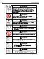
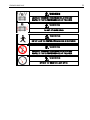
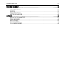
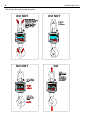
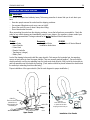
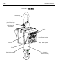
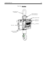
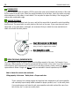
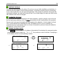
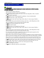
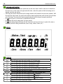
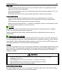
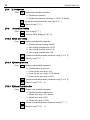
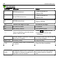
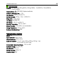
STANDARD CRANE SCALE
OPERATION & SERVICE MANUAL
Models XCL
STANDARD CRANE SCALE
www.mt.com/xpress
2
STANDARD CRANE SCALE
ABOUT THIS MANUAL AND MT XPRESS
Thank you for purchasing an MT Xpress product.
All of our equipment is assembled and packed with great care. If you should find any incorrect item, please
contact your Xpress Dealer immediately.
MT Xpress products are Weights & Measures approved precision weighing instruments. However, you may
want to obtain official certification through your supplier or local Weights & Measures office.
This MT Xpress product was developed, produced, and tested in a METTLER TOLEDO facility that has been
audited and registered according to international ISO 9001 quality standards and ISO 14000 environment
control program. Properly used and maintained, this product will provide years of accurate weighing.
Handle it as you would any piece of fine electronic equipment.
Please READ this manual BEFORE operating or servicing this equipment. Follow the instructions carefully
and save this manual for future reference.
We at MT Xpress want to make sure you received the product you expected. It is important to us that you
are satisfied with your purchase. If there is anything we can help you with, or if you are not satisfied with
either your product or the services received from the Xpress representative, let us know.
How can you reach us?
XPRESS CUSTOMER CARE CENTER, USA
24/7 Information and Support:
www.mt.com/xpress
[email protected]
8 AM to 8 PM EST
Toll Free: 1-866-MTXPRESS
Xpress
Mettler-Toledo, Inc.
60 Collegeview
Westerville, OH 43081
3
STANDARD CRANE SCALE
FCC APPROVAL
This device complies with part 15 of the FCC Rules. Operation is subject to the following two
conditions: (1) this device may not cause harmful interference, and (2) this device must accept
any interference received, including interference that may cause undesired operation.
4
STANDARD CRANE SCALE
WARNING
ONLY PERMIT QUALIFIED PERSONNEL TO SERVICE THIS
EQUIPMENT. EXERCISE CARE WHEN MAKING CHECKS, TESTS,
AND ADJUSTMENTS THAT MUST BE MADE WITH POWER ON.
FAILURE TO OBSERVE THIS PRECAUTION COULD RESULT IN
BODILY INJURY.
110%
WARNING
NEVER LIFT MORE THAN THE CRANE SCALE’S ASSIGNED
WORKING LOAD LIMITED (WLL) RATING.
120%
WARNING
x
DON’T USE ANY LOAD BEARING COMPONENT THAT IS WORN
BEYOND 5% OF THE ORIGINAL DIMENSION.
x
WARNING
DO NOT USE THIS PRODUCT IF ANY OF THE COMPONENTS
ARE CRACKED
WARNING
NEVER POSITION THE LOAD OVER A HUMAN OR ANY BODY PART
9
WARNING
BOTH THE CRANE AND SCALE SAFETY LATCHES MUST BE IN
GOOD CONDITION AND IN PLACE.
WARNING
9
x
THE CRANE SCALE HOOK MUST ALWAYS SUPPORT
THE LOAD CORRECTLY.
WARNING
THE SAFETY LATCH MUST NEVER SUPPORT THE LOAD.
5
STANDARD CRANE SCALE
WARNING
LOADS MAY DISENGAGE FROM CRANE SCALE HOOK AND
SHACKLE IF PROPER PROCEDURES ARE NOT FOLLOWED.
WARNING
DO NOT LET LOADS SWING.
WARNING
DO NOT LEAVE THE CONTROLS WHILE A LOAD IS SUSPENDED
WARNING
LOADS MAY DISENGAGE FROM CRANE SCALE HOOK AND
SHACKLE IF PROPER PROCEDURES ARE NOT FOLLOWED.
WARNING
OPERATE THE CRANE AT A SAFE SPEED.
6
STANDARD CRANE SCALE
CONTENTS
PREPARING THE SCALE FOR USE .................................................................................................... 9
UNPACKING ......................................................................................................................... 9
POWER SUPPLY ................................................................................................................. 12
HANGING THE SCALE .......................................................................................................... 12
SIZING THE SCALE (IMPORTANT NOTE) ................................................................................. 12
VERIFYING THE SCALE......................................................................................................... 13
CALIBRATING THE SCALE ..................................................................................................... 13
TURNING THE SCALE ON/OFF ............................................................................................... 13
ZERO FUNCTION ................................................................................................................. 14
RECOMMENDATIONS FOR USE ............................................................................................. 14
BATTERY NOTICE ................................................................................................................ 14
YOUR XPRESS SCALE AT A GLANCE ............................................................................................... 15
SAFETY NOTICE .................................................................................................................. 15
HANDLING HOIST MOTION ................................................................................................... 16
DISPLAY ............................................................................................................................ 16
CURSORS .......................................................................................................................... 16
KEYBOARD ........................................................................................................................ 17
REMOTE CONTROLLER ........................................................................................................ 18
OPERATING YOUR SCALE ............................................................................................................ 20
PUSH-BUTTON TARE ........................................................................................................... 19
NUMERIC TARE................................................................................................................... 19
CLEAR (REMOVAL OF TARE WEIGHT) .................................................................................... 19
WEIGHING (NORMAL GROSS WEIGHT).................................................................................. 19
ACCUMULATING.................................................................................................................. 19
MANUAL TOTAL .................................................................................................................. 20
AUTO TOTAL....................................................................................................................... 20
RECALL ............................................................................................................................. 21
CLEAR THE ACCUMULATOR .................................................................................................. 21
PEAK WEIGHING OPERATION ............................................................................................... 21
LOAD HOLD ....................................................................................................................... 22
SELF TEST.......................................................................................................................... 22
SLEEP MODE ..................................................................................................................... 22
BRIGHTNESS ADJUSTMENT.................................................................................................. 22
PRINTING .......................................................................................................................... 22
TURNING THE SCALE OFF .................................................................................................... 22
SCALE SOFTWARE SETUP............................................................................................................. 26
SETUP PARAMETERS OVERVIEW........................................................................................... 23
TO ENTER MASTER MODE.................................................................................................... 24
SPECIAL FUNCTION GROUP.................................................................................................. 24
CLEANING AND MAINTAINING YOUR SCALE..................................................................................... 33
REGULAR MAINTENANCE AND INSPECTION............................................................................ 30
CLEANING.......................................................................................................................... 31
POWER SUPPLY AND CHARGING.......................................................................................... 31
TROUBLESHOOTING ............................................................................................................ 32
Continued.
STANDARD CRANE SCALE
7
SERVICING YOUR SCALE ............................................................................................................... 36
TO ENTER SERVICE MODE....................................................................................................33
CALIBRATION GROUP...........................................................................................................33
DISPLAYS...........................................................................................................................37
APPLICATION GROUP...........................................................................................................38
BATTERY REPLACEMENT ......................................................................................................40
APPENDIX .................................................................................................................................. 44
DEFAULT SETUP PARAMETERS..............................................................................................41
ERROR MESSAGES ..............................................................................................................42
SPECIFICATIONS..................................................................................................................43
GEO VALUE TABLE...............................................................................................................44
PHYSICAL DIMENSIONS .......................................................................................................45
8
STANDARD CRANE SCALE
Please follow the proper loading procedure:
DO NOT
DO NOT
DO NOT
DO
9
STANDARD CRANE SCALE
PREPARING THE SCALE FOR USE
UNPACKING
This device is compact and relatively heavy. Take every precaution to insure that you do not strain your
back
− Have two people remove the scale from the shipping container.
− Use a power-lifting device such as a crane or forklift.
− Secure the scale to insure it doesn’t drop when lifting.
− Do not stand under the scale.
When unpacking the scale from the shipping container, insure that all parts are accounted for. Check the
scale for any visible damage and immediately report to your shipper. Any questions, please contact your
local Xpress representative. Package contents for all Xpress Standard Crane Scales include:
Documents
CD-ROM
Product
− Crane Scale
− Quick Start Guide
− Operation & Service Manual
− Upper Shackle
− Installation Instructions
− Lower Hook
− Remote Controller
− Transformer (charger)
− Battery Pack
Look at the drawing below and install the upper shackle. First remove the horizontal pin, two washers,
secure nut and cotter pin from the upper shackle (They are normally packed together.). Second hold the
shackle vertically over the pin extending from the crane scale body shackle. Next, insert the horizontal pin
and both washers over the shackle by inserting. (Each washer should be placed between the shackle and
the vertical pin extending from the scale body.)
Proper installation of the upper shackle (See the next diagram for proper installation.):
Shackle
Nut
Washers (2)
Cotter Pin
Bend as shown to
prevent the nut
from escaping the
horizontal pin
Vertical Pin
Upper Shackle
Cotter Pin
Bend after installation
To prevent the nut from
escaping the horizontal pin
Installation of the Shackle
10
STANDARD CRANE SCALE
Front View – Crane Scale
Shackle body
Cotter pin must be in
place and bent open
to prevent the nut
from falling of the
horizontal pin
Display
Remote control
Infrared windows
Front cover
Quick keyboard
Swivel
Swivel hook assembly
Safety latch
(must be included)
11
STANDARD CRANE SCALE
Rear View – Crane Scale
Safety Latch must
be in place
Cotter pin must be in
place and bent open
Battery removal screws
Battery and
battery cover
Nameplate
Rear cover
Weights and measures
sealing screw
12
STANDARD CRANE SCALE
POWER SUPPLY
A sealed rechargeable lead-acid battery (6V7Ah) powers the scale and is fastened into the back of the scale
by four screws in the rear cover. When you charge the battery for the first time, refer to the section on usage
and maintenance for the battery for more details. You may want to replace the battery if the charging time
reduces after considerable usage.
HANGING THE SCALE
Hang the scale from the bottom hook of a crane, and lock the secure latch to prevent the scale from falling
from the hook. The secure latch is a safety feature of the hook on the crane. If your crane does not have a
safety latch, or the safety latch is damaged, we recommend that you contact the crane manufacturer to
obtain a hook with this safety feature.
Insure that your crane has this feature!
This safety latch prevents the scale from falling
during a no load, or negative load, condition
Area designated as saddle
The scales upper hook should rest here.
SIZING THE SCALE (IMPORTANT NOTE)
The scale capacity should be equal or greater than the lifting capacity of the crane. For Example: If your
crane has a lifting capacity of 1.5 tons we recommend that you chose a 2-ton scale. If you have selected a
scale that has a gross capacity that is less than your crane lifting capacity, please contact your Xpress
representative to obtain a larger unit. Xpress scales are available in various capacities up to 40 tons.
How to choose the correct crane scale size:
Lifting capacity of the crane * Safety factor = Proper scale size.
*If your company has a safety program and regularly trains employees in safe crane operation
and continually inspect safety related hardware for proper operation, use 1 for the safety factor.
If your employees are not trained in safe crane operation and could overload the crane, from
time to time, use 2 or more as a safety factor.
13
STANDARD CRANE SCALE
VERIFYING THE SCALE
The scale has been calibrated in the factory. The end user can use it after installation and verification. In
situations where the weight is used for trading purposes, a verification procedure must be performed by
local or national officials, or by and approved organization. After passing the verification and granted the
metrological certificate, the scale can be used for trade. For non-trade usage, the owner can use the scale
after verification with known test weights.
CALIBRATING THE SCALE
Usually the end user shouldn’t calibrate the scale after installation, except for using the scale for the first
time and performing calibration cycle. An Xpress representative should normally perform this procedure.
The user must have proper test weights and lifting equipment for calibration. Use test weights of at least
20% of scale capacity when calibrating the scale. Test weights of 80% or more of capacity are
recommended. If you notice that the scale is not linear it is possible to perform a three-point calibration.
See Appendix “Factory Default Settings”.
TURNING THE SCALE ON/OFF
Press On/Off , the scale powers up, the display is illuminated all, then displays the component number
and the software version number e.g. “Sr L.1”, then performs a series of self tests. If everything is
ok, the display returns to normal operating condition.
〇Motion 〇Total 〇BAT LOW 〇 〇 〇lb
〇Kg
〇Zero
〇Net
〇Gross
〇mt
Ö
On
Off
〇Tare
Sr l.1
〇Zero
〇Net
〇Gross
〇mt
〇Kg
〇Tare
●Motion ●Total ●BAT LOW ● 〇
●lb
8888888
●Zero
●Net
〇Motion 〇Total 〇BAT LOW 〇 〇 〇lb
Ö
Ö
●Gross
●mt
●Tare
〇Motion 〇Total 〇BAT LOW 〇 〇
Ö
0
〇Zero
〇Net
〇Gross
〇mt
●Kg
●lb
〇 Kg
〇Tare
14
STANDARD CRANE SCALE
ZERO FUNCTION
Power-Up Auto Zero
The scale has power-up auto zero function. Zero range must be less than the preset value in the setting F1.6.3.
Manual Push-Button Zero
In the Gross Mode, press Zero , if the gross value is within the zero range. The display will read zero and
the zero cursor will light.
〇Motion
●lb
〇Total
〇BAT LOW
10
〇Zero
〇Net
●Gross
〇mt
〇Tare
〇
〇
〇Kg
Ö
Zero
Master
Ö
〇Motion
●lb
〇Total
〇BAT LOW
0
●Zero
〇Net
●Gross
〇mt
〇
〇
〇Kg
〇Tare
The scale will not accept a zero, or tare command, when the item being weighed is moving. The motion
lamp lights to indicate that the item is in motion.
In the Gross Mode, if the zero cursor is not lit press ‘Zero’. The zero cursor will light only when the load is 0
+ 1/4 displayed increment.
RECOMMENDATIONS FOR USE
− The end user should not calibrate the scale unless specifically trained on the calibration procedure for
this product.
− When calibrating the scale linearly, perform multi-point linearization.
− Notices for charging the scale battery:
When the battery icon “L BAt” lights, the battery should be replaced.
Do not recharge the battery until it has been fully discharged, as this will shorten the life of
the battery life.
−
−
−
−
−
−
−
−
BATTERY NOTICE
The (6V/5Ah rechargeable lead-acid battery) battery service life will be affected by the charge and
discharge conditions. When used properly, it can be effectively charged/discharged 300 times before
operating time is significantly reduced;
The new battery can provide continuous operation once it is fully charged. The charge time is usually 15
hours if the battery is fully discharged. The charge time will be shorter if the battery is not fully discharged.
Do not short the positive pole (+) and negative pole (-) when replacing the battery.
Charge the battery at least every three months to keep it in good condition.
The battery charge is shorter than normal if the battery is not used for a long period of time, e.g. more
than two months. If this happens, please cycle the battery at least three times by charging it and using it
until fully discharged. This returns the battery to the normal operating condition.
The battery is not warranted due to the service time being greatly influenced by individual use.
The battery charge and scale operating duration will decline with use as is typical with lead-acid
batteries. We recommend replacement of the battery after 300 charging cycles. Replacement batteries
are available from your local Xpress representative.
If the keyboard isn’t in use and the weight hasn’t changed for five minutes, the scale will go into a powersaving mode and will display “SLEEP”. The scale can be reactivated by pushing any key on the quick
keyboard or by operating the remote control.
STANDARD CRANE SCALE
15
YOUR XPRESS SCALE AT A GLANCE
SAFETY NOTICE
Before operating XCL Crane Scale, the scale operator should carefully read and follow the operating
precautions listed below:
− Follow all local and national safety laws.
− Follow all safety precautions from the crane manufacturer.
− Do not lift beyond rated load capacity of the crane, crane scale, sling chains, cables, or any item
attached to the XCL Crane Scale.
− Do not operate the scale in areas designated for pedestrians – these are usually marked.
− Do not position the scale, or load, over personnel.
− Do not operate the crane scale if ropes, slings, cables, chains, etc. show any sign of defects or
excessive wear.
− Before moving the load, make certain that load slings, load chains, or other lifting devices are fully
seated in the saddle of the crane scale hook with hook latch closed.
− Do not drop the load when attached to the crane scale.
− Do not lift the load too rapidly.
− Do not collide the crane scale against any other object.
− Do not operate the crane scale if ropes, slings, cables, chains, etc. show any sign of defects or
excessive wear.
− Before moving the load, make certain that load slings, load chains, or other lifting devices are fully
seated in the saddle of the crane scale hook with hook latch closed.
− At no time should a load be lifted or suspended from the crane scale unless the operator is at the
crane’s master switch or pendulum with the crane power on.
− Keep the load as close to the floor as possible to minimize the possibility of an injury, should the load drop.
− When the crane scale is holding a load, the crane operator should remain at the master switch or pendulum.
− When a hitcher is used, it should be the joint responsibility of the crane operator and the hitcher to see
that hitches are secure and that all loose material has been removed from the load before starting a lift.
− Do not lift loads with ropes, slings, cables, and chains that are not securely fastened around or to the load.
− All ropes, slings, cables, chains, etc. should be removed from the crane scale when not in use.
− Do not use slings, cables, chains, etc. which have not been approved for lifting.
− Replace any damaged or worn items.
− Do not service or adjust the scale when a load is attached.
16
−
−
−
−
−
STANDARD CRANE SCALE
HANDLING HOIST MOTION
After the crane scale hook has been positioned over the load, lower it until the load can be attached to
the scale hook. As the scale hook approaches this level, reduce the speed so that the lowering can be
stopped smoothly and quickly.
If the slings are used to handle the load, the slings should be fully seated in the scale hook (saddle). With
the scale hook latch closed, the scale hook should be started upward slowly until all slack has been taken
out of the slings. Then ensure the load is properly balanced and the slings are properly positioned.
Do not pull or push on a load once it is attached to the scale.
Do not allow the load to swing when it is being moved
Do not make abrupt starts and stops with the crane that could cause the loss of control of the load or
excessively strain the lifting mechanisms (ropes, slings, cables, chains, etc.).
DISPLAY
lb
kg
Motion Total
Zero
Gross
Tare
Net
mt
CURSORS
Zero
This LED lights when the scale is within ±1/4d of gross zero.
Gross
This LED lights when the display is displaying gross weight.
Tare
This LED lights when the display is displaying tare weight.
Net
This LED lights when the display is displaying net weight.
Total
Motion
BAT LOW
This LED lights when the display shows accumulated weight or total count.
This LED lights when the scale is in motion.
This LED lights when the battery voltage is lower than the preset value.
Kg
This LED lights when the current weight unit is kg (kilogram).
lb
This LED lights when the current weight unit is lb (pound).
mt
This LED lights when the current weight unit is mt (metric tonnes).
8
Indicates the current accumulator number.
17
STANDARD CRANE SCALE
KEYBOARD
On
Off
Zero
Master
Clear
Total
Peak
Recall
Hold
Enter
F
Quick keyboard
Keyboard Function Description
Key
Function Description
On/Off
Turns the scale On and Off. Press and hold to turn Off.
Zero/Master
Press the key to set the zero reading of the scale. (in the Gross Mode)
Tare /M
Press the key in the Gross Mode to store the indicated weight as the Tare Weight.
The instrument will display a net weight value of zero until additional weight is
added. The unit will not tare when the scale is in motion.
Clear
When this key is pressed in the Net Mode, the crane scale display returns to the
Gross weight display. Pressing this key in the Gross Mode will initiate a self-test.
Total/Peak
Pressing this key causes the current weight value to be added to the accumulator
and the total LED indicator to flash for three seconds.
Recall
Press the key repeatedly, (on the instrument) displays the gross value, tare
value, the accumulated value, and then returns to the Weight Mode. When
inputting data, pressing the Recall button adds 1 to the reading.
Enter +Zero
Press Enter and release it. Then press Zero to enter into the Master Mode. At
that point you can modify selected parameters. (See Setup F3.)
Enter + Tare
Press Enter and then release it. Then press Tare to sequentially recall all tare
values, noting the tare number in the lower-right display. The main display will
show the stored value.
Enter +Total
Press Enter and release it. Then press Total to enter the Peak Hold Mode.
Enter + Recall
When the weight is stable, press Enter and Recall and the current readings will
be held. Press Clear key and the instrument quits the Weight Hold Mode and
returns to the Normal Weighing Mode.
18
STANDARD CRANE SCALE
REMOTE CONTROLLER
The remote controller can operate the scale the same as the quick
keyboard does. In addition to the functions in the crane scale the
remote control adds; 10 numerical key 0 to 9 plus ID and
Print keys. Some operating modes, such as input of commodity
ID’s, numeric tare, and so on, are only accessed by the remote
controller. These additional keys list as the following:
Off – Press Off key and the scale powers down.
Note: The scale cannot power up via the remote controller.
Use the On/Off key on the quick keyboard to return the scale to use.
transmitting window
METTLER TOLEDO
1
2
3
5
6
7
8
9
0
Off
ID
ID – Used to input commodity ID number
Print – Does not function on this product
indicator light
4
M
F
remote controller
0 to 9 – Entry of tare weight, ID number and entry of capacity,
added load when calibrating.
The remote controller can be operated at distances up to
45 ft (15 m) from the scale. The scale’s structure is fit for harsh
industrial environments including corrosives, humidity, some shock
loading, and dirt.
rubber housing
To test the controller, press any key while observing the indicator
light on the upper left-hand side of the control itself.
Remote Controller
If it fails to light every time a key is depressed, the batteries should
be replaced. This unit requires two (2) AA cell Alkaline batteries. The batteries should be replaced every six
months.
To replace the battery of the remote controller, take the remote controller from the yellow rubber housing. The
procedure is as follows: Push the head of the remote controller slowly out of the rubber housing through the
upper hole on the back of the housing, and pull the black controller out.
To avoiding changing the battery frequently, high-energy alkaline cells are recommended. After replacing the
battery, slip the remote controller into the housing again.
If the remote control fails to function, clean the small window on the front of the scale and on the front of the
controller with alcohol and a clean cloth.
NOTICE
When operating the remote controller, please aim the transmitting
window at the infrared receiving window in the bottom of the front
housing!
19
STANDARD CRANE SCALE
OPERATING YOUR SCALE
PUSH-BUTTON TARE
In Gross Mode, pressing Tare causes the instrument to store the weight reading as the tare value. The net
cursor lights and the scale displays zero.
〇Motion
〇Total
40
〇Zero
〇BAT LOW
〇Kg
〇Gross
〇Tare
〇
〇
●lb
〇Net
〇Motion
Ö
〇Total
Ö
〇mt
●lb
〇BAT LOW 〇 〇
〇Kg
0
〇Zero
〇Gross
〇Tare
●Net
〇mt
0
Tare will not function when the scale is in motion.
NUMERIC TARE
Press the numeric keys on the remote controller to input a manual tare value. Then press Tare key.
〇Motion
●lb
〇Total
〇BAT LOW
100
〇Zero
〇Net
●Gross
〇mt
〇
〇
〇Kg
Ö
4 0+
〇Motion
●lb
〇Total
60
Ö
〇Tare
〇BAT LOW
〇Zero
●Net
〇Gross
〇mt
〇
〇
〇Kg
〇Tare
CLEAR (REMOVAL OF TARE WEIGHT)
In Net Mode, press Clear and the instrument clears the tare weight, displays the gross weight, and the
Gross cursor lights.
〇Motion
●lb
〇Total
〇BAT LOW
60
〇Zero
●Net
〇Gross
〇mt
〇
〇
〇Kg
Ö Clear Ö
〇Tare
〇Motion
●lb
〇Total
〇BAT LOW
100
〇Zero
〇Net
●Gross
〇mt
〇Tare
〇Motion
●lb
〇Total
〇BAT LOW
〇
〇
〇Kg
WEIGHING (NORMAL GROSS WEIGHT)
〇Motion
●lb
〇Total
〇BAT LOW
0
●Zero
〇Net
●Gross
〇mt
〇Tare
〇
〇
〇Kg
Ö load 2000 lb Ö
2000
〇Zero
〇Net
●Gross
〇mt
〇
〇
〇Kg
〇Tare
ACCUMULATING
The accumulation function should be operated in Normal Weighing or Set Point Mode. See setup step.
([F2.5 X], X=0 or 2)
20
STANDARD CRANE SCALE
MANUAL TOTAL
In the Gross or Net Mode, pressing Total causes the weight readings to be added into the corresponding
accumulator (Default value = 0), at the same time the total count adds 1.
〇Motion
●lb
〇Total
〇BAT LOW
2000
〇Zero
〇Net
●Gross
〇mt
〇Tare
〇Motion
●lb
〇Total
〇BAT LOW
2000
〇Zero
●Net
〇Gross
〇mt
〇
〇
〇Kg
〇
Ö
〇
〇Kg
Ö
Total
Peak
Total
Peak
Ö
Ö
〇Tare
〇Motion
●lb
〇Total
〇BAT LOW
2000
〇Zero
〇Net
●Gross
〇mt
〇Tare
〇Motion
●lb
〇Total
〇BAT LOW
2000
〇Zero
●Net
〇Gross
〇mt
●
〇
〇Kg
●
〇
〇Kg
〇Tare
AUTO TOTAL
To complete this operation the scale must be in Auto Total Mode. (See the setting F2.4.2 x=2)
〇Motion
●lb
〇Total
〇BAT LOW
0
〇Zero
〇Net
●Gross
〇mt
〇Tare
〇Motion
●lb
〇Total
〇BAT LOW
0
〇Zero
●Net
〇Gross
〇mt
〇
〇
〇Kg
〇
〇
〇Kg
Ö greater than or
equal to the minimum
accept limit Ö
Ö greater than or
equal to the minimum
accept limit Ö
〇Tare
When the accumulated weight
exceeds 8 digits (or the total
count exceeds 4 digits)Ö
〇Motion
●lb
〇Total
〇BAT LOW
2000
〇Zero
〇Net
●Gross
〇mt
〇Tare
〇Motion
●lb
〇Total
〇BAT LOW
2000
〇Zero
●Net
〇Gross
〇mt
〇Tare
〇Motion
〇lb
〇Total
〇BAT LOW
full
〇Zero
〇Net
〇Gross
〇mt
●
〇
〇Kg
●
〇
〇Kg
●
〇
〇Kg
〇Tare
− After accumulating, the weight readings are added into the accumulator (Default value = 0),
the total count automatically adds 1.
− When the readings are stable and greater than or equal to the minimum accept limit, the
weight readings can be accumulated. (See the Setup F2.4.1)
− Only if the weight readings fall below 10 divisions, return to above the minimum accept limit
and are stable, the next readings can be accumulated automatically!
− When the accumulated weight exceeds 8 digits (or the total count exceeds 4 digits), the
instrument displays “FULL”, at the same time the LED flashes for five seconds (illuminating
for half a second, blanking for half a second), indicating that the accumulator overflows and
that the last accumulation is invalid. Clear the accumulator this time.
21
STANDARD CRANE SCALE
RECALL
〇Motion
●lb
〇Total
〇BAT LOW
〇
2000
〇Zero
〇Net
Ö Recall
Hold
●Gross
〇mt
Ö Recall
Hold
〇Gross
Ö
Hold
〇 〇 ●lb
〇Tare
0011
〇Gross
〇Tare
Ö
Hold
〇Kg
〇 〇 ●lb
〇Net
〇Kg
〇mt
〇 〇
2000
〇Tare
〇Zero
●Gross
〇
●Tare
〇Motion 〇Total 〇BAT LOW
Recall
〇
L 2000
〇Zero
Ö
〇Gross
〇mt
Ö
Hold
〇lb
〇BAT LOW
0
〇Net
〇Kg
〇Gross
〇mt
〇Total
〇Motion 〇Total 〇BAT LOW
Recall
Ö
〇Kg
〇 〇
〇Zero
〇Net
〇Motion
●lb
〇Zero
〇Net
〇Motion 〇Total 〇BAT LOW
Ö
Ö
〇Kg
H 0002
〇Zero
〇mt
Recall
〇Tare
〇Motion 〇Total 〇BAT LOW
Ö
〇
〇Tare
●lb
〇Kg
〇Net
〇mt
〇BAT LOW
〇
CLEAR THE ACCUMULATOR
When accumulation function is enabled ([F2.4.2 X] X=1 or X=2)
〇Motion
●lb
〇Total
〇BAT LOW
2000
〇Zero
〇mt
Ö Recall
Hold
Ö
●Gross
Recall
Ö
Hold
〇Motion
●lb
Ö
〇Total
0
〇Net
〇Zero
〇Net
〇 〇 ●lb
H 0002
〇Gross
〇
〇Kg
〇Tare
〇Motion 〇Total 〇BAT LOW
〇Zero
〇mt
〇
〇Gross
〇mt
〇Tare
〇Zero
Ö
F
〇 〇 〇lb
sure
〇Net
Enter
〇Kg
●Tare
〇Motion 〇Total 〇BAT LOW
Ö Clear Ö
〇Kg
Ö
〇Gross
〇Motion
●lb
〇
〇Tare
〇Total
〇Net
〇Kg
〇mt
〇BAT LOW
2000
〇Zero
〇Net
●Gross
〇mt
〇Tare
〇Motion
●lb
〇Total
〇BAT LOW
〇 〇
〇Kg
PEAK WEIGHING OPERATION
〇Motion
●lb
〇Total
〇BAT LOW
10
〇Zero
〇Net
Ö
Ö
Zero
●Gross
〇mt
●Gross
Enter
F
+ Total
Peak
〇Tare
2015
Ö
〇Zero
〇Net
〇 〇 ●lb
0
●Zero
〇mt
〇Kg
Ö
〇Tare
〇Motion 〇Total 〇BAT LOW
Master
〇 〇
〇Kg
〇Net
●Gross
〇mt
〇 〇 ●lb
10
〇Zero
●Gross
〇Tare
〇Kg
〇Tare
〇Motion 〇Total 〇BAT LOW
Ö Clear Ö
〇 〇
〇Net
〇Kg
〇mt
In normal
weighing
mode
22
STANDARD CRANE SCALE
LOAD HOLD
〇Motion
●lb
〇Total
〇BAT LOW
0
●Zero
〇Net
●Gross
〇mt
〇 〇
〇Kg
Ö Add 2000 lb
Enter
F
〇Tare
Ö
+
Recall
Hold
〇Motion
●lb
〇BAT LOW
2000
Ö
Clear Ö
〇Total
〇Zero
〇Net
●Gross
〇mt
〇Tare
〇Motion
●lb
〇Total
〇BAT LOW
2000
〇Zero
〇Net
●Gross
〇mt
〇 〇
〇Kg
〇 〇
〇Kg
〇Tare
SELF TEST
In Gross Mode, press Clear and the instrument will enter into a self test. Display reads “00000”, ”11111”,
…, ”99999”, ”-----“, cursors and the remaining battery capacity messages [bAt X] (X=4, 3, 2, 1, 4-high 1low). The instrument returns to the Normal Weighing Mode automatically.
SLEEP MODE
If the keyboard isn’t in use and the weight hasn’t changed for five minutes, the scale will go into a powersaving mode and will display “SLEEP”. Pushing the quick keyboard or operating the remote controller can
awaken the scale. To disable the SLEEP function, select the parameter “0” in the Setup F3.1.
BRIGHTNESS ADJUSTMENT
To adjust the brightness, select the parameter “0” or “1” in the Setup F3.2. See the “Factory Parameters
Setup” and “Factory Default Settings” in the Appendix. The default parameter “0” indicates bright LED, the
parameter “1” indicates bright LED and the LED brightness will darken automatically if the weight isn’t
obviously changed for five minutes, the parameter “2” indicates the LED brightness can be adjusted
automatically according to ambient light levels.
PRINTING
Printing the Ticket
〇Motion
●lb
〇Total
〇BAT LOW
1000
〇Zero
〇Net
●Gross
〇mt
〇Tare
〇 〇
〇Kg
Ö Press Print Ö
〇Motion
〇lb
〇Total
〇BAT LOW
--p-〇Zero
〇Net
〇Gross
〇mt
〇 〇
〇Kg
〇Tare
Only the remote controller has this Print key.
Printing the Accumulated Data
In the Total Display Mode, press Print to output the accumulated weight. The numeral in the following
set of parentheses represents the accumulator number. If the current accumulator number is zero, the
parentheses can be omitted.
TURNING THE SCALE OFF
Press On/Off on the quick keyboard or Off on the remote controller, the scale powers down and the display
goes blank.
23
STANDARD CRANE SCALE
SCALE SOFTWARE SETUP
Several parameters in the scale can be changed to enable you to customize the scale to your individual needs.
In the Master Mode, only parameters F3, F4, F5 and F6 can be changed. To change the parameters F1 and
F2, please see “Servicing your Scale”
SETUP PARAMETERS OVERVIEW
Service Technician Settings
F1
Data interface
F1.2
Digital filter
F1.5
Tare operation
F1.6
Zero and
zero tracking
F1.6.2
Auto zero
tracking
F1.6.3
Power-up
auto-zero
F1.6.4
Manual
pushbutton zero
F2
Application
function
F2.4
Accumulation
function
F2.4.1
Minimum
accept limit
F2.4.2
Accumulation
mode
F2.5
Weighing mode
F2.6
Unit Conversion
F2.7
Gravity Adjustment
F1.7
Motion
detection
F3
Special function
F3.1
F3.2
Backlight mode
selection
F4.1.1
Output mode
selection
F3.3
Battery selection
F4.1.3
Baud rate
selection
F4.1.4
Data bit and
parity bit selection
F3.4
ID function
F3.6
Set point function
F3.6.1
High Set point value
F3.6.3
F3.7
Memory retention
F3.8
Enable remote
controller function
F1.9
Capacity
selection
F1.10
Interval
selection
F1.11
Linearity
calibration
F1.12
Calibration
F1.14
Span
adjustment
F4
Parameters setup
for serial port
F4.1
COM1
Alarm mode selection
F1.8
Weight unit
selection
User Settings
Sleep mode
selection
F3.6.2
Low Set point value
F1.7.1
Motion
detection range
F1.13
Zero
adjustment
Setup Parameters
F4.1.5
Checksum and
STX selection
F4.1.6
On-Demand output
format selection
F4.1.8
Printer selection
F5
Self test selection
F5.1
Expanded display
selection
F5.2
Scale calibration
parameters
F5.3
Display test
F5.4
Keyboard test
[F5.5
Serial port test
F5.6
Settings printout
F6
Re-enter or
complete setup
F6.1
Finish set up
24
STANDARD CRANE SCALE
TO ENTER MASTER MODE
Press Enter/F and Zero/Master in turn and the instrument displays “F3.1” and enters into the Master
Mode. Many of the parameters, such as F3, F4, F5, can be modified. To modify the parameters F1 and F2,
the scale must be in Service Mode. (See Servicing Your Scale.)
During the setup, the function of each key lists as below:
Tare key—Used to select setup group or to setup parameters
Zero key—To step back through the setup procedure
ENTER/F key —To confirm the selected parameter
When inputting numerical data:
Tare key —The flashing digit shifts one position to the left indicating the digit that can be modified
Recall key—The flashing digit increments on each depression
SPECIAL FUNCTION GROUP
[F3
] Special Function
Press: Tare —Skips to step [F4 ]
Enter —Advances to step [F3.1
Zero —Returns to step [F2
[F3.1
]
]
X] Sleep Mode Selection
Press:
Tare —Displays next selectable parameter:
0—Disables sleep mode
1—Enables sleep mode (default)
If the keyboard isn’t in use and the weight isn’t obviously changed for five minutes, the
instrument will go into a power-saving mode and will display “SLEEP”. Pressing the
quick keyboard or operation the remote controller will awaken it.
Enter — Accepts the selected parameter and advances to the next step [F3.2 X]
Zero —Returns to step [F3 ]
[F3.2
0] Brightness Adjustment
Press:
Tare —Displays next selectable parameters:
0—Brightness adjustment off (default)
1—Brightness adjustment on. The brightness will be off automatically
after five minutes of nonuse.
2—Auto on/off (bright / dim according to ambient light levels)
Enter —Accepts the selected parameter and advances the step [F3.3 X]
Zero —Returns to step [F3.1 X]
25
STANDARD CRANE SCALE
[F3.4
0] ID Function
Press:
Enter —Disables ID function. Advances to step [F3.6 ] in Set Point Mode or to
step [F3.7 ],
Tare—Displays [F3.4 1]. Press Enter key to enable ID function, in Set Point Mode
advances to step [F3.6 ], or to step [F3.7 X].
When disables ID function, each tare memory and accumulator has only one,
default number is zero.
Note: The function is only for the Service Mode.
[F3.6
] Set Point Function (External output is only available via an option kit.)
Press: Tare—Disables Set point function, skips to step [F3.7 X].
Enter —Enables Set point function, displays [F3.6.1 ].
Note: The function is only for the Service Mode.
[F3.6.1 ] Inputting the High Set Point Value
After one second the instrument displays:
[000000]—Use Tare and Recall key to input the high set point value, or key in the value directly from the
remote controller. Then press Enter key to confirm advances to step [F3.6.2 ].
[F3.6.2 ] Inputting the Low Set Point Value
After one second the instrument displays:
[000000]—Use Tare and Recall key to input the low Set Point Value or key in the value directly from the
remote controller. Then press Enter key to confirm and advance the step [F3.6.3 X].
Note: Only after Set Point Mode is selected in step [F2.5 X] (set X=2), this function can be available. The
high Set Point Value must be greater than the lower value.
[F3.6.3
1] Display Alarm Mode Selection
Press:
Tare —Displays next selectable parameters:
0—The weight reading doesn’t flash when the weight “reaches” the Set Point Value.
1—The weight reading flashes on and off when the weight “reaches” the Set Point
Value.
Enter —Accepts the selected parameter and advances to the next step [F3.7 X]
Zero —Returns to step [F3.6
]
The word “reaches” means that the weight reading is greater than or equal to the high Set Point Value or
less than or equal to the low Set Point Value.
26
STANDARD CRANE SCALE
[F3.7
0] Memory Retention
Press:
Enter —Disable memory retention and advances to the next step [F3.8 X]
Tare— Displays [F3.7 1]. Press Enter key to enable memory retention and advance to
the next step [F3.8 X].
When Memory retention is enabled, the instrument returns to the last status (Zero,
Gross/Net status, etc.) when powering up.
Zero —Returns to step [F3.7
[F3.8
]
1] Enable Remote Controller Function
Press:
Enter —Enables remote controller. The cursor “Remt” lights in normal operation and
advances to the next step [F4 ].
Tare —Displays [F3.8 0]. Press Enter key to confirm and to disable the remote
controller. This advances on to the next step [F4 ].
Zero —Returns to step [F3.7
[F4
X]
Zero —Returns to step [F3
]
Zero —Returns to step [F4
]
] setup parameters for serial port
Press:
Tare------Not enter the entry of the setup for serial port, advances to step [F5 ]
Enter ------Enters the entry of the setup for serial port, advances to step [F4.1 ].
Zero------Returns to step [F3
[F4.1
]
] com1
Press:
Tare------Not enter the entry of the setup for COM1, advances to step [F5 ]
Enter ------Enters the entry of the setup for COM1, advances to step [F4.1.1 X]
Zero------Returns to step [F4
[F4.1.1
]
X] output mode selection
Press:
Tare------Displays next parameter, selectable parameters:
0------On-Demand mode (default)
1------Continuous data mode
Enter ------Accepts the selected parameter, advances to step [F4.1.3 ]
Zero------Returns to step [F4.1 ]
[F4.1.3
] baud rate selection, displays the current baud rate [001200] after a second (default)
Press: Tare------Displays next baud rate, selectable baud rates: 300, 1200, 2400, 4800, and
9600
Enter------Accepts the selected parameter, advances to step [F4.1.4 X]
Zero------Returns to step [F4.1.1 X]
27
STANDARD CRANE SCALE
[F4.1.4
X] data bit and parity bit selection
Press: Tare------Displays next parameter, selectable parameters:
0------7 data bits, parity bit is zero
1------7 data bits, odd parity
2------7 data bits, even parity (default)
3------8 data bits, no parity bit (uses for transmitting characters)
Enter------Accepts the selected parameter, advances to step [F4.1.5 X]
Zero------Returns to step [F4.1.3 ]
[F4.1.5
0] Checksum and STX selection
Press: Tare------Displays next parameter, selectable parameters:
0------Disables Checksum (default)
1------Enables Checksum. Checksum is defined as the 2’s complement of
the seven low order bits of the binary sum of all characters preceding the
checksum character, including the <STX> and <CR> characters.
Enter------Accepts the selected parameter, advances to step [F4.1.6 X]
Zero------Returns to step [F4.1.4 X]
[F4.1.6
X] On-Demand output format selection
Press: Tare------Displays next parameter, selectable parameters:
0------No data output
1------Single-line: displayed weight (default)
2------Single-line: Gross, Tare, Net
3------Multi-line: Gross, Tare, Net
Enter ------Accepts the selected parameter, advances to step [F4.1.8 X]
Zero------Returns to step [F4.1.5 X]
[F4.1.8
X] printers selection
Press: Tare------Displays next parameter, selectable parameters:
1------Selects micro-printers (default). No print format No.2 (microprinters must have Chinese font library if needed.)
2------Selects PQ30 printers
Enter------Accepts the selected parameter, advances to step [F5 X]
Zero ------Returns to step [F4.1.6 X]
Self test group
28
[F5
STANDARD CRANE SCALE
] Self-Test Selection
Press:
Tare —Advances to step [F6 ]
Enter —Enters the entry of self-test setup and displays [F5.1 X].
Zero —Returns to step [F4
[F5.1
]
X] Expanded Display Selection
Press: Tare—Displays next selectable parameters:
0—Disables the expanded display (default)
1—Enables the expanded display. In Weighing Mode, the instrument displays
internal scale interval.
(Note: One display scale interval is equal to ten internal scale intervals.)
Enter —Accepts the selected parameter, advances to step [F5.2 0]
Zero —Returns to step [F5 ]
[F5.2
0] Display Scale Calibration Parameters
Press:
Enter —Skips to step [F5.3 0]
Tare—- Displays [F5.2 1], press Enter key, displays [FinE0], after two seconds
displays [XXXXXX], records or modifies the empty scale reading, then press
Enter key, displays [SPAn1], after two seconds displays [XXXXXX], records or
modifies the span coefficient, then press Enter key, displays [LinE1], after two
seconds displays [XXXXXX], records or modifies the linearity coefficient No.1,
press Enter key, displays [LinE2], after two seconds displays [XXXXXX],
records or modifies the linearity coefficient No.2, press Enter key, advances to
next step.
Zero —Returns to step [F5.1 X]
[F5.3
0] Display Test
Press: Enter —Advances to step [F5.4 0]
Tare—Displays [F5.3 1]. Press the Enter key and the instrument enters the display
test and displays all possible numbers from all zeros through all nines. Then all the
cursors illuminate and it performs an internal check on the memory. Advances to
step [F5.4 0].
Zero —Returns to step [F5.2 0]
Note: If the instrument finds any errors during the memory check it will display a corresponding error code.
[F5.4
0] Keyboard Test
Press: Enter —Advances to step [F5.5 0]
Tare —Displays [F5.4 1]. Press Enter key, the instrument enters the keyboard test,
operators press a key, and the instrument displays a corresponding key code, press
Enter key to end this test, advances to next step.
Zero —Returns to step [F5.3 0]
29
STANDARD CRANE SCALE
[F5.5
0] Serial Port Test (Not used on this product.)
Press: Enter —Advances to step [F5.6 0]
Tare —Displays [F5.5 1]. Short-circuit TXD and RXD pin of the output connector,
and press Enter key, the instrument Enter s the serial port test. The weight display
reads the transmitting numeral on the two leftmost digits, and the receiving numeral
on the two rightmost digits, the two numerals should be same. The display reading
begins from “01”, then “02”, “03” … “09”, “00”, “01”, goes round and round. Press
Enter key to end this test, advances to next step.
Zero —Returns to step [F5.4 0]
[F5.6
0] Settings Printout (Not used on this product.)
Press: Enter —Advances to step [F6 ]
Tare —Displays [F5.6 1]. Press Enter key, the instrument outputs the settings.
Zero —Returns to step [F5.5 0]
[F6
] Re-Enter or Complete Setup
Press: Tare —Advances to step [F1 ] start over
Enter —Goes to [F6.1 X] finish setup
Zero —Returns to step [F5 ] previous selection
[F6.1 X] Finish Setup
Press: Tare —Displays next selectable parameters:
1—Saves your selection
2—Restores the previous parameters
3—Restores the factory default, displays “SvrE?” (Save).
Enter —Accepts the selected parameter
Zero —Returns to step [F6 ]
If item 1or 2 is selected, the scale quits the setup program and returns to Normal
Weighing Mode; If item 3 is selected it displays “SvrE?” (Save).
Press Enter key, the instrument restores the factory default parameters, quits the setup
program, and returns to Normal Weighing Mode.
Press Tare key, returns to step [F6 ]
QUIT THE SETUP PROGRAM
To quit the setup program and return to Normal Weighing Mode, follow the procedure as below:
Pressing the Clear key, displays [F6 ]; Pressing the Enter key displays [F6.1 1]; To save the setup
parameters press the Enter key; The scale quits the setup program and returns to Normal Weighing Mode.
30
STANDARD CRANE SCALE
CLEANING AND MAINTAINING YOUR SCALE
WARNING
DISCONNECT ALL POWER TO THIS UNIT
BEFORE INSTALLING, SERVICING,
CLEANING, OR REMOVING THE FUSE.
FAILURE TO DO SO COULD RESULT IN
BODILY HARM AND/OR PROPERTY
DAMAGE.
REGULAR MAINTENANCE AND INSPECTION
Connection
Check the connecting pieces, the split pins and setscrews for looseness or deformity. Replace any missing
pieces or tighten loose screws/pins at once.
Check for wear
Check for wear and straightness
Excessive wear
Never replace a pin with
a bolt or any other fastener!
Check that pin is seated
Check for wear alignment
Check shackle for opening
Check for crack and deformation
Ch
ec
kf
or
op
en
ing
10° maximum twist
Check for wear, crack, and deformation
Surface damage
Check the shackle and hook surfaces for mechanical damage such as cracks, etc. and discard the
damaged ones and replace them!
31
STANDARD CRANE SCALE
Deformation
− Check the opening (See the upper figure) of the hook. When the value is 10% greater than the initial
dimension, the hook must be discarded!
− Check the twist deformation of the hook. When the twist angle of the hook body is greater than 10°, the
hook must be discarded!
− The shackle and hook should not have any plastic deformation or they must be discarded!
Abrasion and Corrosion
− Check the shackle and hook for abrasion and corrosion. The actual dimensions in use on the
dangerous section should not less than 95% of their initial dimension or they must be discarded!
− DO NOT permit to repair the shackle and hook system by welding!
− Replace the secure latch periodically, i.e., whenever it is damaged or broken. This will prevent the scale
from falling should it encounter a no load or zero load.
CLEANING
Clean the keyboard with a soft cloth that has been dampened with a mild window cleaner or detergent.
DO NOT use any type industrial solvent or chemicals.
Regular inspections with written service records periodically by a qualified service technician are also
recommended.
POWER SUPPLY AND CHARGING
A sealed, rechargeable lead-acid battery (6V7Ah) powers the XCL Crane Scale. The operator should check
the remaining battery capacity often. Change the battery when the low battery indicator “z” lights. When the
scale displays [L Bat], indicating that the battery capacity is too low for the scale to work, the battery must
be charged immediately or the scale will power down automatically.
Charging
Remove the bolt on the top of the rear cover and pull out the battery. Plug the charger shipped with the scale
into a power outlet. Then plug another small end of the charger’s power cord into the charging port of the
battery and charge the scale. The charger indicator is red to start and when the indicator turns yellow,
charging is complete.
WARNING
−
−
−
−
−
Charge the battery when it has been not in use for a period of more than three months.
Charging time: 24 hours
Daily charging time: 8-10 hours, 20°C above; 12-16 hours, 20°C below.
Keep the battery away from any heat source and avoid exposure to the sun.
When not in use for a long time, remove the battery.
Remote Controller Power Supply
Two ordinary alkaline cells (“AA” size, 1.5V) are used. If the indicator light does not flash when operating
the remote controller, the battery must be immediately replaced.
32
STANDARD CRANE SCALE
TROUBLESHOOTING
The instrument is designed for durable, reliable, and virtually error free operation. If problems do occur after
powering on, do not attempt to repair the scale or instrument before you have determined the source of the
problem. Begin by performing the diagnostic tests described in the previous section. If the problem persists,
you can use the error codes table below to help identify the problem.
WARNING
If there is anything wrong with the crane scale, please
contact the local Xpress representative.
33
STANDARD CRANE SCALE
SERVICING YOUR SCALE
For the following services, please contact your Xpress representative at www.mt.com/xpress.
CAUTION
WARNING
DISCONNECT ALL POWER TO THIS UNIT
BEFORE INSTALLING, SERVICING, CLEANING,
OR REMOVING THE FUSE. FAILURE TO DO
SO COULD RESULT IN BODILY HARM
AND/OR PROPERTY DAMAGE.
BEFORE CONNECTING OR DISCONNECTING ANY INTERNAL
ELECTRONIC COMPONENTS OR INTERCONNECTING WIRING
BETWEEN ELECTRONIC EQUIPMENT, ALWAYS REMOVE POWER
AND WAIT AT LEAST THIRTY (30) SECONDS BEFORE ANY
CONNECTIONS OR DISCONNECTION’S ARE MADE. FAILURE TO
OBSERVE THESE PRECAUTIONS COULD RESULT IN DAMAGE TO
OR DESTRUCTION OF THE EQUIPMENT, OR BODILY HARM.
TO ENTER SERVICE MODE
Remove the hexagonal seal screw on the right side of the front cover and press the push-button in the hole.
The instrument displays “F1” and enters the Service Mode. All parameters including the calibration
parameters can be modified.
Note: Entering Service Mode voids weights and measures approval and the unit must be reproved.
During the setup, the function of each key lists as below:
Tare key—Used to select setup group or setup parameters,
Zero key—To step back through the setup procedure,
ENTER/F key —To confirm the selected parameter,
When inputting numerical data:
Tare key —The flashing digit shifts one digit leftwards, this digit can be modified.
Recall key—The flashing digit increments on each depression.
Note: in the following description, the “F” in “[FX.X ]” displays on the far left side of the display.
CALIBRATION GROUP
[F1
] Weighing Functions
Press: Tare —Skips to step [F2
]
Enter —Enters the calibration group, displays [F1.2 X]
[F1.2
X] Digital Filter
Press: Tare —Displays next digital filter parameter, selectable parameters:
0—Filter disabled
1—Light filter
2—Medium filter (default)
3—Heavy filter
Enter —Accepts the selected parameter, enters step [F1.5 X]
Zero —Returns to step [F1
]
34
[F1.5
STANDARD CRANE SCALE
X] Tare Operation
Press: Tare —Display next selectable parameters:
0—Disables tare operation
1—Enables tare operation, tare range: 0~100% F.S.(default)
Enter—Accepts the selected parameter, enters step [F1.6 ]
Zero —Returns to step [F1.2 ]
[F1.6
] Zero and Zero Tracking
Press: Tare —Skips to step [F1.7 ]
Enter —Enters next step, displays [F1.6.2 X]
[F1.6.2 X] Auto Zero Tracking
Press: Tare —Displays next selectable parameters:
0—Disables auto zero tracking (default)
1—Zero tracking threshold value: ±0.5d
2—Zero tracking threshold value: ±1.0d
3—Zero tracking threshold value: ±3d
Enter —Accepts the selected parameter, advances to step [F1.6.3 X]
Zero —Returns to step [F1.6
]
[F1.6.3 X] Power-up Auto Zero
Press: Tare —Displays next selectable parameters:
0—Disables power-up auto zero
1—Power-up auto-zero range: ±2%
2—Power-up auto-zero range: ±10% (default)
3—Power-up auto zero range: ±100%
Enter —Accepts the selected parameter, advances to step [F1.6.4 X]
Zero —Returns to step [F1.6.2
X]
[F1.6.4 X] Manual Push-button Zero
Press: Tare —Displays next selectable parameters:
0—Disables manual pushbutton zero
1—Manual zero range: ±2% (default)
2—Manual zero range: ±20%
3—Manual zero range: ±100%
Enter —Accepts the selected parameter, advances to step [F1.7
Zero —Returns to step [F1.6.3
X]
]
35
STANDARD CRANE SCALE
[F1.7
] Motion Detection
Press: Tare —Skips motion detection setup and advances to step [F1.8 ]
Enter —Enters motion detection setup, advances to step [F1.7.1 X]
[F1.7.1 X] Motion Detection Range
Press: Tare —Displays next selectable parameters:
0—Disables motion detection
1—Motion detection range: ±0.5d (default)
2—Motion detection range: ±d
3—Motion detection range: ±3d
Enter —Accepts the selected parameter, advances to step [F1.8
X]
Zero —Returns to step [F1.7 ]
[F1.8 X] Weight Unit Selection
Press: Tare —Displays next selectable parameters:
0—Displays weight unit: kg
1—Displays weight unit: lb
2—Displays weight unit: t
3—Displays weight unit: mt (metric tonne)
Enter —Accepts the selected parameter, advances to step [F1.9 ]
Zero —Returns to step [F1.7 ]
[F1.9] Capacity Selection
After two seconds displays the current capacity.
Press: Tare —Enters the entry of capacity and displays “000000”. The far left digit flashes use
Tare and Recall keys to input the capacity value, or key in the capacity value directly via
the numerical key.
Enter —Confirms and advances to step [F1.10 ]
Zero —Cancels the selection, Returns to step [F1.8 ]
36
STANDARD CRANE SCALE
[F1.10] Interval Selection
After two seconds it displays the current interval “XXXXXX”.
Press: Tare —Displays next interval
Enter —Confirms the selected interval, advances to step [F1.11 X]
Capacity and interval selection must meet the values in the next table. The others are shown but are
only available on heavier capacity units.
Interval
Capacity
100
250
500
1000
2000
2500
5000
10000
15000
20000
25000
30000
40000
50000
60000
80000
100000
0.02
0.05
0.1
√
√
√
√
√
√
0.2
0.5
√
√
√
√
√
√
√
1
√
√
√
√
2
5
10
20
50
√
√
√
√
√
√
√
√
√
√
√
√
√
√
√
√
√
√
√
√
√
√
√
√
√
√
√
√
√
√
Do not use
Capacity and Interval
[F1.11
X] Linearity Calibration
Press : Tare —Display next selectable parameters:
0—Disables linearity calibration (default)
1—Enables linearity calibration
Enter —Accepts the selected parameter, advances to step [F1.12
0]
Zero —Returns to step [F1.9 ]
[F1.12
0] Calibration (Do NOT use this step unless you have sufficient test weights - See below.)
Press: Enter —Skips to step [F1.13
0]
Tare —Displays [F1.12 1], press Enter again, the instrument enters the calibration
procedure.
STANDARD CRANE SCALE
37
DISPLAYS
Standard Calibration (F1.11=0)
[E SCL]—Remove all weight from the scale, press Enter key once the scale has settled and
is stable, the instrument displays [15 SCL], counts down from 15 to 0 while recording zero,
then displays [Add Ld].
Note: When displaying [E SCL], press Zero to return to step [F1.12 0].
[Add Ld]—Pick up test weights of at least 20% of scale capacity. A test weight of 80% or
more of capacity is recommended for highest accuracy. Then press Enter , the instrument
displays [000000], the leftmost digit flashes, use Tare and Recall keys to input the test
weights value, or key in the value directly from the remote controller, then press the Enter
key to confirm your selection, the instrument displays [15 S[L] , counts down from 15 to 0
while recording span, then displays [[AL d], indicating that the calibration is completed, and
displays [F1.13 0] after 2 seconds.
Note: When displaying [Add Ld], press Zero to return to step [E SCL].
For best results, the test weight must relate to the lowest significant digit. A test weight not corresponding to
the lowest significant digit will be automatically rounded to the closest digit. If the scale has a scale capacity
yielding a lowest significant digit of 5 kg then adding 4 kg would cause an error.
Three-Point Linear Calibration (F1.11=1)
[E SCL]—Remove all weight from the scale, press Enter once the scale is stable, the instrument
displays
[5 SCL], counts down from 15 to 0 while recording zero, then displays [Add HI].
[Add HI]—Pick up test weights of at least 50 to100% of scale capacity. Test weights of 80% or
more of capacity are recommended for highest accuracy. Then press Enter, the instrument displays
[000000], the leftmost digit flashes, use Tare and Recall key to input the test weights value, or key
in the value directly from the remote controller, then press Enter key to confirm, the instrument
displays [15 SCL] , counts down from 15 to 0 while recording high span, then displays [Add L0]
Note: When displaying [Add HI], press Zero to return to step [E SCL].
For best results the test weight must relate to the lowest significant digit. A test weight not corresponding to
the lowest significant digit will be automatically rounded to the closest digit. If the scale has a scale capacity
yielding a lowest significant digit of 5 kg then adding 4 kg would cause an error.
[Add L0]—Pick up test weights of at least 10 to 50% of scale capacity, then press Enter, the
instrument displays [000000], the leftmost digit flashes, use Tare and Recall key to input the test
weights value, or key in the value directly from the remote controller, then press Enter key to
confirm, the instrument displays [15 S[L] , counts down from 15 to 0 while recording low span,
then displays [[AL d], indicating that the calibration is completed, and displays [F1.13 0] after 2
seconds.
Note: When displaying [Add L0], press Zero to return to step [Add HI].
For best results the test weight must relate to the lowest significant digit. A test weight not corresponding to
the lowest significant digit will be automatically rounded to the closest digit. If the scale has a scale capacity
yielding a lowest significant digit of 5 kg then adding 4 kg would cause an error.
38
STANDARD CRANE SCALE
[F1.13
0] Zero Adjustment
Press:
Enter —Skips to step [F1.14
0]
Tare —Displays [F1.13 1], advances to zero adjustment. Remove all weight from the
scale, press Enter key, the instrument displays [15 S[L] and counts down from 15 to 0
while recording zero, then displays [F1.14 0].
Zero —Returns to step [F1.12
[F1.14
0]
0] Span adjustment
Press: Enter —Skips to step [F2
0]
Tare —Displays [F1.14 1], advances to span adjustment.
Press Enter key, the instrument displays [000000], use Tare and Recall key to input the
test weights value, or key in the value directly from the remote controller, press Enter to
confirm, the instrument displays [15 S[L] and counts down from 15 to 0 while recording
span, then advances to next step.
Zero —Returns to step [F1.13
0]
Note: Pick up test weights on the scale in weighing mode, then enters the Setup, advances to step [F1.14
0], repeat the span adjustment operation following the above step.
Warning: The test weight value must be divided exactly by significant figure of the selected scale interval.
For example, significant figure of scale interval 0.02 is 2.
APPLICATION GROUP
[F2
] Application Function
Press: Tare —Skips to step [F3
]
Enter —Enters application group, displays [F2.4 ]
[F2.4
] Accumulation Function
Press: Tare —Disables accumulation function, advances to step [F2.5 ]
Enter —Advances to step [F2.4.1 ]
Zero —Returns to step [F2
]
[F2.4.1 1] Minimum Accept Limit to be Accumulated, After One Second Displays [XXXXXX]
Press: Zero —Enters the entry of minimum acceptable weight which will be accumulated
the unit displays [000000], the leftmost digit flashes. Use Tare and Recall key to
input the minimum accept limit, or key in the value directly from the remote
controller. Then
Press: Enter key to confirm, advances to step [F2.4.2 X],
Press: Zero key to cancel the input, Returns to step [F2.4 ].
The unit will not accept the next accumulated value unless the weight value has changed by ten digits since
the last accumulation.
39
STANDARD CRANE SCALE
[F2.4.2
X] Accumulation Mode
Press: Tare —Displays next selectable parameters:
0—Disables accumulation (default)
1—Manual accumulation
2—Auto accumulation (only if the weight readings fall below 10 divisions,
then return to or above the minimum accept limit and are stable, the next
readings can be accumulated.)
Enter —Accepts the selected parameter, enters step [F2.5 X]
Zero —Returns to step [F2.4.1 ]
[F2.5
X] Weighing Mode
Press: Tare —Displays next selectable parameters:
0—Normal Weighing Mode (default)
1—Peak hold mode, the instrument displays the detected Maximum
weight and holds it, simultaneously the cursor “PEAK” lights. In this mode
the accumulation, function is not available.
2—Set point mode (not available without an installed option).
Enter —Accepts the selected parameter, advances to step [F3 ]
Zero —Returns to step [F2.4
]
[F2.6 X] Unit Conversion
Press: Tare —Displays next selectable parameters:
0—no conversion
1—kg
2—lb
If the current display unit is kg, select the parameter “2” to convert kilograms into pounds.
If the current display unit is lb, select the parameter “1” to convert pounds into kilograms.
Enter —Accepts the selected parameter, advances to step [F2.7 ]
Zero —Returns to step [F2.5 ]
[F2.7 12] Gravity GEO Adjustment
Press: Tare —Displays next selectable parameters: 0~31
The scale is calibrated with a Geo code of 12 at the factory. To adjust the factory
calibration to your specific area, refer to Appendix E (page 41) for your Geo code. Enter
the new Geo code and calibration will automatically be adjusted for your desired location.
Enter —Accepts the selected parameter, advances to step [F3 ]
Zero —Returns to step [F2.6 ]
40
STANDARD CRANE SCALE
BATTERY REPLACEMENT
CAUTION
RISK OF EXPLOSION IF BATTERY IS
REPLACED BY AN INCORRECT TYPE OR
CONNECTED IMPROPERLY.
DISPOSE OF USED BATTERIES ACCORDING
TO LOCAL LAWS AND REGULATIONS.
Thumbscrews (2)
36
Clamp screws (2)
27 Battery assembly
45 Battery Polarity
1
Battery
Red wire = (+) Positive
Black wire = (-) Negative
8
1.
2.
3.
4.
5.
Turn the scale off by pressing the on/off pushbutton on the keyboard
Slowly remove the battery assembly all from the top of the scale – it is held by two thumbscrews
Loosen the two screws that clamp the battery into the battery assembly
Remove the two plastic battery connectors from the pins on the battery
Replace and reconnect the battery – please note that the red wire is (+) and the black wire is (-)
polarity
CAUTION
RISK OF EXPLOSION IF BATTERY IS REPLACED WITH WRONG TYPE OR
CONNECTED IMPROPERLY. CONNECT RED WIRE TO POSITIVE (+) BATTERY
TERMINAL AND BLACK WIRE TO NEGATIVE (-) BATTERY TERMINAL!
6. Replace the battery and tighten the two screws
7. Replace the battery assembly.
8. Dispose of the “used” (old) battery in according to local laws and regulations.
41
STANDARD CRANE SCALE
APPENDIX
DEFAULT SETUP PARAMETERS
F1
Scale Interface
F1.2
Digital filter
F1.5
Default
F3
Special Function Group
Default
2
F3.1
Sleep mode
1
Tare operation
1
F3.2
Backlight mode
0
F1.6.2
Auto zero tracing
0
F3.3
Battery selection
0
F1.6.3
Power up zero range
2
F3.4
ID function
0
F1.6.4
Pushbutton zero range
1
F3.6.3
Display alarm mode selection
0
F1.7.1
Motion range
1
F3.7
Memory retention
0
F1.8
Unit selection
0
F3.8
Remote controller function
1
F1.9
Scale capacity
NA
F4
Serial port Setup
F1.10
Interval
NA
F4.1.1
Output mode selection
F1.11
Linearity calibration
0
F4.1.3
Baud rate selection
F1.12
Calibration
0
F4.1.4
Data bit and parity bit selection
2
F1.13
Zero adjustment
0
F4.1.5
Checksum selection
0
F1.14
Span adjustment
0
F4.1.6
On-Demand output format
selection
1
F2
Environment
Default
F4.1.8
Printers selection
1
F2.4.1
Minimum accept limit
0
F5
Diagnosis
F2.4.2
Accumulation mode
0
F5.1
Expanded display
F2.5
Weighing mode
0
F5.2
Scale calibration parameters
0
F2.6
Unit conversion
2
F5.3
Display test
0
F2.7
Gravity adjustment
12
F5.4
Keyboard test
0
F5.5
Serial port test
0
F5.6
Settings printout
0
Default
0
1200
default
0
42
STANDARD CRANE SCALE
ERROR MESSAGES
Error Code
Description
Remedy
E1
EPROM checkout error
E2
Internal RAM checkout error
E3
EEPROM checkout error
E35
Calibration test weight is too light.
Add additional test weight
E37
The scale is in motion
Re-calibration
Full
Data memory overflow
Clear transaction record
—--
Under load indication, under load is below
power-on auto zero limit.
—-
Overload indication, overload is 9 divisions
greater than full capacity.
Decrease the load check that the scale
has not been damaged
z BAT LOW
Low battery voltage
Charge the battery
L bAt
Low battery voltage, power off automatically
in a minute.
Charge the battery immediately
SLEEP
Automatically enters the SLEEP mode when
the weight isn’t obviously changed and the
scale isn’t in use for 5 minutes.
Press any key on the quick keyboard or
the remote controller to activate the
scale.
1.Power off and back on
2.Replace PCB
1.Power off and back on
2.Replace PCB
1.Power off and back up
2.Replace EEPROM
1.Press Zero and empty the scale
2.Check for loose load cell cable
connections
STANDARD CRANE SCALE
SPECIFICATIONS
Capacity: 100 kg/250 lb, 250 kg/500 lb, 500 kg/1000 lb, 1 ton/2500 lb, 2.5 ton/5000 lb,
5 ton/10,000 lb
Accuracy Class: lll NTEP 5000 (Optional certificate)
Indication Stabilizing Time: < 10s
Safe Overload: 200% Full Scale (F.S.)
Ultimate Overload: 100 kg – 5 ton: ≥ 500% F.S.
Fatigue Life: 1 million times
Tare Range: 0 to100% F.S.
Zero Range: ± 2% F.S. or 20% F.S.
Operating Temperature: –20°C to +50°C
Relative Humidity: 10% to 95%, non-condensation
Storage Temperature: –30°C to +60°C
Enclosure Protection Class: IP65
Main Specifications of Load Cell
Model: TSA
Input Resistance: 2200 ± 50 Ω
Output Resistance: 2000 ± 50 Ω
Load Cell Sensitivity: 1.5 ± 0.1 mv/v (100 kg, 250 kg, 500 kg, 1 ton)
2 ± 0.3 mv/v (2.5 ton, 5 ton)
Compensated Temperature Range: –10˚C to +40˚C
Excitation Voltage: 5 ± 0.5V (DC)
Safe Overload: 200% F.S
Ultimate Overload: 500% F.S
Protection Class: IP67
43
44
STANDARD CRANE SCALE
GEO VALUE TABLE
Use the following geo codes if you relocate the XCL to a site other than the original location where it was
calibrated.
Northern
and
Southern
latitude in
degrees and
minutes
0° 0′ — 5° 46′
5° 46′ — 9° 52′
9° 52′ — 12° 44′
12° 44′ — 15° 6′
15° 6′ — 17° 10′
17° 10′ — 19° 2′
19° 2′ — 20° 45′
20° 45′ — 22° 22′
22° 22′ — 23° 54′
23° 54′ — 25° 21′
25° 21′ — 26° 45′
26° 45′ — 28° 6′
28° 6′ — 29° 25′
29° 25′ — 30° 41′
30° 41′ — 31° 56′
31° 56′ — 33° 9′
33° 9′ — 34° 21′
34° 21′ — 35° 31′
35° 31′ — 36° 41′
36° 41′ — 37° 50′
37° 50′ — 38° 58′
38° 58′ — 40° 5′
40° 5′ — 41° 12′
41° 12′ — 42° 19′
42° 19′ — 43° 26′
43° 26′ — 44° 32′
44° 32′ — 45° 38′
45° 38′ — 46° 45′
46° 45′ — 47° 51′
47° 51′ — 48° 58′
48° 58′ — 50° 6′
50° 6′ — 51° 13′
51° 13′ — 52° 22′
52° 22′ — 53° 31′
53° 31′ — 54° 41′
54° 41′ — 55° 52′
55° 52′ — 57° 4′
57° 4′ — 58° 17′
58° 17′ — 59° 32′
59° 32′ — 60° 49′
60° 49′ — 62° 9′
62° 9′ — 63° 30′
63° 30′ — 64° 55′
64° 55′ — 66° 24′
66° 24′ — 67° 57′
67° 57′ — 69° 35′
69° 35′ — 71° 21′
71° 21′ — 73° 16′
73° 16′ — 75° 24′
75° 24′ — 77° 52′
77° 52′ — 80° 56′
80° 56′ — 85° 45′
85° 45′ — 90° 00′
Height above sea-level in meters
0
325
325
650
650
975
975
1300
0
1060
5
5
6
6
7
7
8
8
9
9
10
10
11
11
12
12
13
13
14
14
15
15
16
16
17
17
18
18
19
19
20
20
21
21
22
22
23
23
24
24
25
25
26
26
27
27
28
28
29
29
30
30
31
1060
2130
4
5
5
6
6
7
7
8
8
9
9
10
10
11
11
12
12
13
13
14
14
15
15
16
16
17
17
18
18
19
19
20
20
21
21
22
22
23
23
24
24
25
25
26
26
27
27
28
28
29
29
30
30
2130
3200
4
4
5
5
6
6
7
7
8
8
9
9
10
10
11
11
12
12
13
13
14
14
15
15
16
16
17
17
18
18
19
19
20
20
21
21
22
22
23
23
24
24
25
25
26
26
27
27
28
28
29
29
30
3200
4260
3
4
4
5
5
6
6
7
7
8
8
9
9
10
10
11
11
12
12
13
13
14
14
15
15
16
16
17
17
18
18
19
19
20
20
21
21
22
22
23
23
24
24
25
25
26
26
27
27
28
28
29
29
1300
1625
1625
1950
1950
2275
2275
2600
2600
2925
2925
3250
3250
3575
7460
8530
1
2
2
3
3
4
4
5
5
6
6
7
7
8
8
9
9
10
10
11
11
12
12
13
13
14
14
15
15
16
16
17
17
18
18
19
19
20
20
21
21
22
22
23
23
24
24
25
25
26
26
27
27
8530
9600
1
1
2
2
3
3
4
4
5
5
6
6
7
7
8
8
9
9
10
10
11
11
12
12
13
13
14
14
15
15
16
16
17
17
18
18
19
19
20
20
21
21
22
22
23
23
24
24
25
25
26
26
27
9600
10660
0
1
1
2
2
3
3
4
4
5
5
6
6
7
7
8
8
9
9
10
10
11
11
12
12
13
13
14
14
15
15
16
16
17
17
18
18
19
19
20
20
21
21
22
22
23
23
24
24
25
25
26
26
10660
11730
0
0
1
1
2
2
3
3
4
4
5
5
6
6
7
7
8
8
9
9
10
10
11
11
12
12
13
13
14
14
15
15
16
16
17
17
18
18
19
19
20
20
21
21
22
22
23
23
24
24
25
25
26
Height above sea-level in feet
4260
5330
3
3
4
4
5
5
6
6
7
7
8
8
9
9
10
10
11
11
12
12
13
13
14
14
15
15
16
16
17
17
18
18
19
19
20
20
21
21
22
22
23
23
24
24
25
25
26
26
27
27
28
28
29
5330
6400
2
3
3
4
4
5
5
6
6
7
7
8
8
9
9
10
10
11
11
12
12
13
13
14
14
15
15
16
16
17
17
18
18
19
19
20
20
21
21
22
22
23
23
24
24
25
25
26
26
27
27
28
28
6400
7460
2
2
3
3
4
4
5
5
6
6
7
7
8
8
9
9
10
10
11
11
12
12
13
13
14
14
15
15
16
16
17
17
18
18
19
19
20
20
21
21
22
22
23
23
24
24
25
25
26
26
27
27
28
45
STANDARD CRANE SCALE
PHYSICAL DIMENSIONS
Model
Capacity
[lb]
Resolution
[lb]
XC01L-00
XC02L-00
XC03L-00
XC04L-00
XC05L-00
XC06L-00
250
500
1000
2500
5000
10,000
0.1
0.2
0.5
1
2
5
Dimensions [“]
H
C
22.8
D
φ1
F
Shipping Information
φ2
φ3
1.6
2
4.1
2.4
0.8
1.8
2.4
5.5
3.5
1.1
15
29.5
10
11
L [" ]
W [" ]
H [" ]
WT [lb]
31.5
31.5
31.5
31.5
31.5
31.5
19.7
19.7
19.7
19.7
19.7
19.7
15.7
15.7
15.7
15.7
15.7
15.7
77.0
77.0
77.0
77.0
77.0
77.0
46
Notes
STANDARD CRANE SCALE
Xpress
Mettler-Toledo, Inc.
60 Collegeview
Westerville, OH 43081
5/2004
MTX04-OM032.1E
STANDARD CRANE SCALE
www.mt.com/xpress