1
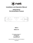
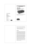
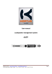
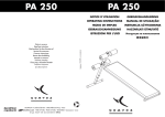
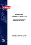
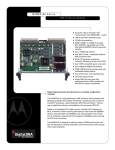
SM70
TS100/TS200 Series
PA Speakers
INSTALLATION AND OPERATION MANUAL
REV 4.00 March 22, 2005
Northern Airborne Technology Ltd.
1925 Kirschner Road
Kelowna, BC, Canada.
V1Y 4N7
Telephone (250) 763-2232
Facsimile (250) 762-3374
Copyright 2005 by Northern Airborne Technology
CONFIDENTIAL AND PROPRIETARY TO NORTHERN AIRBORNE TECHNOLOGY LTD.
SM70 Rev. 4.00
TS100/TS200 Series PA Speakers Manual
IMPORTANT INFORMATION
This manual has been produced to provide information unique to the
TS100/TS200 Series PA Speakers. Some of this information has been
published previously in the SM02 Service manual (AA20/22/23
PA110/220 Series Loudhailer/PA Systems).
The information presented in this manual is for reference purposes
only, and is intended to provide general information that can be used
by the installer/technician to gain a fundamental understanding of the
product. Information for specific units can be requested by contacting
the Product Support Department at NAT Ltd.
Mar 22, 2005
Page ii
ENG-FORM: 820-0110.DOT
CONFIDENTIAL AND PROPRIETARY TO NORTHERN AIRBORNE TECHNOLOGY LTD.
SM70 Rev. 4.00
TS100/TS200 Series PA Speakers Manual
Periodically NAT will release manual amendments. In order to maintain the most
accurate and up to date manual these amendments should be carried out immediately
upon receipt and recorded on the following amendment record.
AMENDMENT RECORD
Amendment Amendment
Number
Date
Section(s)
Changed
Date
Entered
Entered By
Note: Revision 4.00 is the first public release of this document
1
Nov 30/06
2
Performed at factory
Insert any Amendment Instruction sheets after this page.
Mar 22, 2005
Page iii
ENG-FORM: 820-0110.DOT
CONFIDENTIAL AND PROPRIETARY TO NORTHERN AIRBORNE TECHNOLOGY LTD.
INSTALL_OPS
MANUAL AMENDMENT
Manual: SM70 (TS100_TS200)
Document # SM70\Install_Ops\809-0001
Amendment #: 1
Amendment Date: Nov 30, 2006
The purpose of this amendment is to add drawings to the manual.
Amendment Instructions:
Remove Pages
Replace With Pages
2-3 Rev 4.00
2-3 to 2-4 Rev 4.00 Amendment 1
Remove Drawings (Section 2)
Replace or add Drawings (Section 2)
-
TS100WR\403-0 Rev 1.00
TS100WR\405-0 Rev 1.00
TS200WR\403-0 Rev 1.00
TS200WR\403-1 Rev 1.00
TS200WR\405-0 Rev 1.01
TS200WR\403-0 Rev 1.10
TS200WR\403-1 Rev 1.10
TS200WR\405-0 Rev 1.10
1
2
Note: Ensure that all drawings are inserted in the order shown on the latest drawing lists.
3
Update the Amendment Record sheet at the front of the manual.
4
Insert this page into the manual after the Amendment Record sheet (page iii).
Manual Amendment ends after the following amended pages
Amendment # 1
Nov 30, 2006
Page 1
ENG-FORM: 809-0109.DOT
CONFIDENTIAL AND PROPRIETARY TO NORTHERN AIRBORNE TECHNOLOGY LTD.
SM70 Rev. 4.00
TS100/TS200 Series PA Speakers Manual
Table of Contents
Section
Title
1
Description
1.1
1.2
1.3
1.4
1.4.1
1.4.2
1.5
Introduction
Purpose of Equipment
Features
Specifications
Performance Specifications
Physical Specifications
System Configuration
2
Installation
2.1
2.2
2.3
2.3.1
2.3.2
2.3.3
2.3.4
2.3.5
2.4
2.5
2.5.1
Introduction
Unpacking and Inspection
Installation Procedures
Warnings
Cautions
Cabling and Wiring
Mechanical Installation
Post-Installation Checks
Continued Airworthiness
Installation Drawings
Reference Drawings
3
Operation
3.1
3.2
3.3
3.3.1
Introduction
General
Operation Specifics
Cautions
Mar 22, 2005
Page
1-1
1-1
1-1
1-1
1-1
1-1
1-2
2-1
2-1
2-1
2-1
2-1
2-2
2-2
2-2
2-2
2-2
2-3
3-1
3-1
3-1
3-1
Page iv
ENG-FORM: 820-0110.DOT
CONFIDENTIAL AND PROPRIETARY TO NORTHERN AIRBORNE TECHNOLOGY LTD.
SM70 Rev. 4.00
TS100/TS200 Series PA Speakers Manual
Section 1 Description
1.1
Introduction
This manual contains information on the TS100WR and TS200WR PA Speakers. Some
TS100/TS200 Series PA Speakers information will also be provided for reference only.
Information in this section consists of purpose of equipment, features and specifications.
1.2
Purpose of Equipment
The TS100 and TS200 Series PA Speakers are lightweight loudspeakers that can be
used for both internal and external aircraft applications. The TS100WR/TS200WR Series
PA Speakers are used with the PA110, PA220 and PA250 series amplifiers.
1.3
Features
This series of speakers offers full 100- and 200-watt capability, and the driver assembly and
mechanical parts are field replaceable for ease of maintenance.
1.4
Specifications
1.4.1
Performance Specifications
Loudhailer
TS100 (S-100S)
TS100S (S-100R)
TS100R (SD-210R)
TS100A
TS100WR
TS200
TS200WR
Input Power
100 Wrms
100 Wrms
100 Wrms
100 Wrms
100 Wrms
100 Wrms
100 Wrms
Impedance
11 Ohms
11 Ohms
11 Ohms
11 Ohms
11 Ohms
11 Ohms
11 Ohms
Frequency
275 – 8000 Hz
275 – 8000 Hz
275 – 7000 Hz
275 – 7000 Hz
275 – 7000 Hz
275 – 7000 Hz
275 – 7000 Hz
Output Level @ 1m
116 dB (1 W, 1500 Hz signal)
114 dB (1 W, 1200 Hz signal)
110 dB (1 W, 1000 Hz signal)
110 dB (1 W, 1000 Hz signal)
110 dB (1 W, 1000 Hz signal)
110 dB (1 W, 1000 Hz signal)
110 dB (1 W, 1000 Hz signal)
Note: These specifications are given for guidance only. If further information is required,
please contact the Product Support department at NAT.
1.4.2
Physical Specifications
See the appropriate Mechanical Installation drawings (922-0) in Section 2 of this
manual for the PA Speaker physical specifications.
Mar 22, 2005
Page 1-1
ENG-FORM: 800-0106.DOT
CONFIDENTIAL AND PROPRIETARY TO NORTHERN AIRBORNE TECHNOLOGY LTD.
TS100/TS200 Series PA Speakers Manual
1.5
SM70 Rev. 4.00
System Configuration
The TS100/TS200 PA Speaker should be chosen to match the audio output power of
the PA System amplifier. As a general rule, the system should have one speaker driver
(minimum) for each 100 watts of audio power.
Failure to follow this rule can result in the speakers being overdriven, leading to high
levels of distortion and premature failure of the speaker drivers.
End of section 1
Page 1-2
Mar 22, 2005
ENG-FORM: 800-0106.DOT
CONFIDENTIAL AND PROPRIETARY TO NORTHERN AIRBORNE TECHNOLOGY LTD.
SM70 Rev. 4.00
TS100/TS200 Series PA Speakers Manual
Section 2 Installation
2.1
Introduction
Information in this section consists of: unpacking and inspection procedures, installation
procedures, post-installation checks, and installation drawings.
2.2
Unpacking and Inspection
Unpack the equipment carefully and locate the warranty card. Inspect the unit visually
for damage due to shipping and report all such claims immediately to the carrier
involved. Note that each unit should have the following:
- TS100/TS200 Series PA Speaker
- Warranty Card
- Release certification
Verify that all items are present before proceeding and report any shortage immediately
to your supplier.
2.2.1
Warranty
Complete the warranty card information and send it to NAT when the installation is
complete. If you fail to complete the warranty card, the warranty will be activated on
date of shipment from NAT.
Note: An appropriately rated facility, e.g. Certified Aircraft Repair Station, must install
this equipment in accordance with applicable regulations. NAT Ltd’s warranty is
not valid unless the equipment is installed by an authorized NAT Dealer. Failure
to follow any of the installation instructions, or installation by a non-certified
individual or agency will void the warranty, and may result in a non-airworthy
installation.
2.3
Installation Procedures
2.3.1
Warnings
Stand clear, this equipment operates at an intense sound level. Personnel must be kept
away from the direct loudspeaker beam.
2.3.2
Cautions
Do not operate the equipment in a hangar or in confined areas.
Mar 22, 2005
Page 2-1
ENG-FORM: 805-0105.DOT
CONFIDENTIAL AND PROPRIETARY TO NORTHERN AIRBORNE TECHNOLOGY LTD.
TS100/TS200 Series PA Speakers Manual
SM70 Rev. 4.00
Do not operate the equipment with snow, water or other foreign matter in the
loudspeaker horn.
Do not clean the loudspeaker with compressed air.
Be careful only to operate the siren for 3 cycles at a time and trill for a short 2 to 3
second burst. The driver is unable to withstand constant signals – it requires a Duty
cycle (see above) to permit the unit to cool down.
2.3.3
Cabling and Wiring
All unshielded wire shall be selected in accordance with AC43.13-1B Change 1,
Paragraphs 11-76 through 11-78. Wire types should be to MIL-W-22759 as specified in
AC43.13-1B Change 1, Paragraphs 11-85, 11-86, and listed in Table 11-11.
For shielded wire applications, use Tefzel MIL-M-27500 or MIL-M-81044 shielded wire
with solder sleeves (for shield terminations) to make the most compact and easily
terminated interconnect. Follow the wiring diagrams in Section 2.5 as required.
2.3.4
Mechanical Installation
The installing agency is responsible for the design, engineering and installation of the
mounting bracket for the Speaker. Careful consideration should be given to the
operating environment and the mechanical forces acting upon the unit.
When installing the speakers, ensure that there is adequate airflow to cool the
speaker drivers, and that the speaker phasing is correct.
Note: The speakers are designed for intermittent operation only.
CAUTION
Failure to install the TS200WR speakers as shown in the
relevant wiring diagram(s) will result in PERMANENT AND
IRREPARABLE DAMAGE to the speaker drivers.
Both speaker drivers MUST be wired in phase to ensure
proper performance and to prevent damage.
Page 2-2
Mar 22, 2005
ENG-FORM: 805-0105.DOT
CONFIDENTIAL AND PROPRIETARY TO NORTHERN AIRBORNE TECHNOLOGY LTD.
SM70 Rev. 4.00
2.3.5
TS100/TS200 Series PA Speakers Manual
Post-Installation Checks
Ensure all connectors are tight and the mechanical installation is sound.
When the PA system installation is complete, carry out a full performance test to ensure
that all components of the system (including the speaker) are functioning correctly. For
full post-installation check information, refer to Section 2 of SM35, PA110/220 High
Power Audio Amplifiers Service manual.
2.4
Continued Airworthiness
Maintenance of the TS100/TS200 Series speakers is ‘on condition’ only. Periodic
maintenance of this product is not required.
2.5
Installation Drawings
DRAWING
REV.
DESCRIPTION
TYPE
TS100WR\403-0
1.00
Lightweight Speaker
Interconnect
TS100WR\405-0
1.00
Lightweight Speaker
Connector Map
TS100WR\922-0
1.10
Speaker, Lightweight
Mech. Installation
TS200WR\403-0
1.10
Dual Speaker, Lightweight
Interconnect
TS200WR\403-1
1.10
Dual Speaker, Lightweight
Interconnect
TS200WR\405-0
1.10
Dual Speaker, Lightweight
Connector Map
TS200WR\922-0
1.01
Dual Speaker, Lightweight
Mech. Installation
TS100WR
TS200WR
2.5.1
Reference Drawings
The following drawings are included for reference only.
DRAWING
REV.
DESCRIPTION
TYPE
1.00
Speaker, Lightweight
Mounting Diagram
TS100A\920-0
1.00
Speaker, Lightweight
Mounting Diagram
TS100A\922-0
1.10
Speaker, Lightweight
Mech. Installation
1.10
Speaker, Lightweight
Mech. Installation
TS100
TS100\920-0
TS100A
TS100RA
TS100RA\922-0
Mar 22, 2005
ENG-FORM: 805-0105.DOT
Page 2-3
Amendment #1
Nov 30, 2006
CONFIDENTIAL AND PROPRIETARY TO NORTHERN AIRBORNE TECHNOLOGY LTD.
TS100/TS200 Series PA Speakers Manual
DRAWING
SM70 Rev. 4.00
REV.
DESCRIPTION
TYPE
TS200\920-0
1.00
Dual Speaker, Lightweight
Mounting Diagram
TS200\922-0
1.00
Dual Speaker, Lightweight
Mech. Installation
TS200
Section 2 ends after these Drawings
Page 2-4
ENG-FORM: 805-0105.DOT
Mar 22, 2005
Amendment #1
Nov 30, 2006
CONFIDENTIAL AND PROPRIETARY TO NORTHERN AIRBORNE TECHNOLOGY LTD.
Confidential and Proprietary to NAT
Confidential and Proprietary to NAT
SM70 Rev. 4.00
TS100/TS200 Series PA Speakers Manual
Section 3 Operation
3.1
Introduction
Information in this section consists of the functional and operational procedures for the
TS100 and TS200 Series PA Speakers.
3.2
General
The TS100 and TS200 Series PA Speakers are lightweight loudspeakers that can be
used for both internal and external aircraft applications. The TS100WR/TS200WR Series
PA Speakers are used with the PA110, PA220 and PA250 series amplifiers.
3.3
Operation Specifics
The TS100/200 Series Speakers have no normal user operational aspects.
3.3.1
Cautions
Do not operate the equipment in a hangar or in confined areas.
Do not operate the equipment with snow, water or other foreign matter in the
loudspeaker horn.
Do not clean the loudspeaker with compressed air.
Be careful only to operate the siren for 3 cycles at a time and trill for a short 2 to 3
second burst. The driver is unable to withstand constant signals – it requires a Duty
cycle to permit the unit to cool down.
End of section 3
Mar 22, 2005
Page 3-1
ENG-FORM: 806-0105.DOT
CONFIDENTIAL AND PROPRIETARY TO NORTHERN AIRBORNE TECHNOLOGY LTD.