1
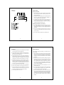
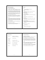
Operating Manual
DXA-5Da
Passive XLR Adapter for DSLR
Camcorders
Address
BeachTek Inc.
1855 Kirschner Rd.
Suite 230
Kelowna, British Columbia
Canada V1Y 4N7
This operating manual explains the function settings and how to
use the adapter to record audio into the camera.
Phone
416-690-9457
Email
[email protected]
Website
www.beachtek.com
©BeachTek Inc. 2010
Thank You for Purchasing a BeachTek Product
• Before using this high quality device, please read this guide
thoroughly to obtain the highest performance.
• Please contact us if you have any problems or questions.
Description
The BeachTek DXA-5Da is a two-channel, transformer balanced
XLR adapter for attaching external microphones and other audio
gear to any DSLR camera that has a built-in mic jack. It can also
be used with any camcorder or other audio recording device that
has a mic jack. The DXA-5Da uses high quality balancing
transformers, which are completely noise free for superb audio.
The DXA-5Da is very easy to set up and use. It allows you to
connect a wide variety of audio devices including professional
microphones, wireless systems and even take a feed from a house
sound system or mixer. The built-in level meters show the input
signal strength at a glance while the trim controls allow you to
adjust the input level for optimum recording. The headphone jack
lets you monitor the audio that is coming out of the adapter.
A unique feature of the DXA-5Da is the ability to control the wild
swings of the Auto Gain Control that plague most cameras. This
dramatically reduces noise during quiet moments of recording.
The adapter mounts to the bottom of the camera and can also
be mounted to any standard tripod.
1
Before You Begin
Quick Setup Guide
These instructions refer to the use of this adapter with DSLR
1)
Mount the DXA-5Da adapter to the camera.
cameras unless otherwise noted.
2)
Connect one of the supplied output cables from the MIC jack
on the adapter to the MIC input on the camera.
1) Since there are no preamplifiers in the passive adapter, it is
3)
Install a fresh alkaline or lithium battery in the adapter.
4)
Set the GROUND switch on bottom of adapter to G1.
DSLR cameras have very noisy preamplifiers so a sensitive
5)
Set the LIN/MIC switch to MIC for microphones or LIN for mixers.
microphone will give you the best signal to noise ratio.
6)
Connect your audio sources to the adapter.
7)
Set the M/S switch to M for mono when using one channel or
important that you use sensitive condenser microphones
to get the best performance out of the DSLR camera. Most
2) Do a few test recordings and check playback on the camera
to S for stereo when using two channels.
to be sure that the audio is captured as expected. Since there
is no output audio jack on most cameras, there is no way to
8)
function, please read the information supplied in this manual
ensure that what you are monitoring is being recorded by the
for a detailed explanation of how this feature works.
camera.
9)
3) The audio that you hear from headphones connected to the
phone jack on the adapter is not exactly the same as the audio
you will hear on play back from the camera.
4) Note that you cannot monitor audio on playback through this
Set the AGC DSBL switch to the left for off. Before using this
Turn the adapter PWR switch on. The LCD screen should
activate.
10) Adjust the level controls for each channel fully clockwise to 10
for no attenuation. Adjust the trim controls only if the input signals
exceed -36 dBu on the level meters.
11) Note that the level meters on the adapter monitor the signal
device.
strength from your sound source. It is normal if you do not see
5) Please read and understand the use of the AGC DSBL feature
before using this function.
the meters move. They will only register when using sensitive
type microphones or when you are attached to a mixer or
wireless microphone.
12) Plug your headphones into the PHONE jack on the adapter and
Supplied Accessories
adjust the VOLUME control to a comfortable level. Be sure that
you hear audio on both channels from the connected devices.
• 3.5 mm to 3.5 mm output cable
• 3.5 mm to 2.5 mm output cable
13) Do a test recording and playback to ensure that the captured
audio is satisfactory. Note that you will not hear audio on playback
through the adapter.
2
Adapter Connectors and Controls
3
G1/G2 Switch
Ground selection switch
PWR Switch
Activates power for the LCD meter, AGC disable feature and
headphone amplifier
LEFT and RIGHT XLR Inputs
Two balanced XLR inputs attach to professional microphones or
other audio gear such as mixers and sound boards
LIN/MIC Switches
Selects microphone or line level input on each channel
LEFT and RIGHT Level Controls
Trim controls to adjust output level on each channel
R AUX Input
Unbalanced input for connecting to a wireless receiver or other
device that has a mini-plug output cable
MIC OUT
Output jack for connection to the camera
M/S Switch
Selects mono or stereo output mode
AGC DSBL Switch
Disables the Auto Gain Control feature in the camera
Volume Control
Adjusts the headphone volume level
LCD Display
Back lit display shows the level meters, battery indicator and
PHONES
Headphone jack to monitor the audio coming out of the adapter
4
position of the various switches on the adapter
5
Setup Guide
Battery Installation
1) The DXA-5Da operates on one 9 volt battery. We recommend
that you use either an alkaline or lithium type battery for the
longest operating time.
2) The adapter only requires battery power for operating the LCD
panel, AGC disable feature and headphone amplifier. No
power is required to pass the audio signal.
3) To install the battery simply open the cover by pushing on the
end of the cover to unclip it. Insert the battery with the "+"
positive terminal lined up with the "+" indicator on the battery
compartment. Replace the battery cover.
Mounting the Adapter on the Camera
1) Line up the mounting bolt on top of the adapter to the tripod
hole on the underside of the camera. Carefully turn the top
mounting knob to the right to screw the adapter squarely into
the camera.
2) Use one of the supplied output cables and connect one end
to the MIC OUT of the adapter and the other end to the MIC
IN on the camera.
3) You can also mount the adapter to any standard tripod.
6
7
Basic Operation
Initial Setup
1) Connect your microphones or other audio gear to the adapter
via the XLR inputs or AUX mini-plug input.
After following the above Initial Setup, you should be ready to
start recording.
2) Set the LIN/MIC switch to either MIC when connecting microphones or most wireless receivers, or to LIN when taking a
line level feed from a mixing board.
1) The level meters on the adapter monitor the signal strength
from your sound source. It is normal if you do not see the
meters move. They will only register when using sensitive type
3) Set the G1/G2 switch to G1. You may have to change this to
the G2 setting if you encounter any ground loop noise when
microphones or when you are attached to a mixer or wireless
microphone.
attached to a mixing board. You will need to do a test recording
and playback to determine the best position for your setup.
2) Keep the trim controls at the maximum setting for unity gain.
Only adjust the trim controls if the input signals exceed -36
4) Set the M/S switch to M for mono when using one microphone. Set the unused channel trim control fully clockwise so
that it does not interfere with the working channel. When using
two microphones, you should normally set the switch to S
for stereo to keep each channel separated.
5) Set the AGC DSBL switch to the left so that it is deactivated.
6) Set the LEFT and RIGHT trim controls fully clockwise to 10.
dBu on the level meters. If you have a mixer or some other
form of amplified signal connected to the adapter, adjust the
trim controls to give you a peak reading of -36 dBu. This is
the "weet spot" for attaining the highest signal to noise ratio
from the camera preamplifiers.
3) Adjust the VOLUME control for the headphones to a comfortable listening level.
7) Plug your headphones into the PHONES jack to monitor the
4) Do a test recording and play back the audio to determine if
audio. Be sure that the VOLUME control is set low to avoid
the captured audio is acceptable. Note you will not be able
excessively loud audio from damaging your hearing.
to monitor the playback audio from the adapter.
8) Turn the adapter PWR switch to ON.
5) The Auto Gain Control (AGC) in the camera will vary the
amount of gain depending upon the input signal level. During
quiet moments, the AGC will increase the gain, which will also
increase the amount of hiss from the camera preamplifiers.
See "Using the AGC DSBL Feature" below to reduce this
problem.
8
9
Advanced Operation
Features
Using the AGC DSBL Feature
Inputs
This switch is a means to disable the wild swings of the Auto Gain
• Two transformer balanced XLR connectors
Control in the camera. It activates an inaudible tone of 20 kHz
• One unbalanced mini-jack
to the left channel (when set to STEREO operation) that prevents
Outputs
the Auto Gain Control from increasing the gain to its maximum
• Unbalanced stereo mini-jack for connection to the camera
level. This reduces the hiss that normally occurs when the camera
is recording audio during quiet moments. The tone is recorded
by the camera but can be easily filtered out if necessary. You can
still use the left channel for recording normal audio at the same
time as the AGC DSBL feature is active.
When this feature is active, you will see 2 or 3 bars indicate on
Headphone Monitor
• Built-in headphone amplifier with volume control
• 3.5 mm phone jack
Auto Gain Control Disable
• Controls wild swings of the AGC in the camera to reduce hiss
the level meter for the left channel (when the M/S switch is set
Level Meters
to S for stereo) which verifies that the tone is being sent to the
• Stereo LCD Meter to show input signal strength
camera.
Trim Controls
You may also want to record audio only on the right channel and
leave the left channel unused for the AGC control signal if this
tone presents a problem down the line. In this case, you should
set the M/S switch to S for stereo to keep the AGC signal separated
• Adjusts signal level on each channel from unity to no output
MIC/LINE Switches
• Allows connections of microphones or mixers for versatility
Balancing Transformers
from the recorded signal.
Again, it is important that you do a test recording and play back
the audio to see if it is acceptable.
The AGC DSBL feature will lower the gain on the camera, which
will require a sensitive microphone for best results.
• Premium wide-bandwidth transformers for superb audio
• Shielded in a custom deep drawn mu-metal cover for very
quiet operation
Power
• Easily replaceable 9 volt battery
• Low battery indicator
Case
• High impact-resistant polycarbonate
10
Specifications
Input Level
11
Warranty Information
MIC setting: -36 dBu ideal
Limited Two Year Warranty
LINE setting: -10 to +4 dBu ideal
This warranty covers any defects or malfunction in your new
BeachTek adapter for two years from date of purchase.
Output Level
Nominal MIC levels
BeachTek will replace or repair any defective or malfunctioning
adapter, within the warranty period, at no charge. The warranty
Frequency
Response
20 Hz to 20 kHz (+/- 3dB)
does not cover damage resulting from accident, alteration, misuse
or abuse. The device must be sent to our service center at your
Level Meter
Calibrated from -54 dBu to -33 dBu
Battery Type
One 9 volt alkaline battery
Dimensions
6" x 3" x 1.7" (L x W x H)
expense.
Should you require service please contact us first before returning
the unit to us. Return instructions can be found on our website
at www.beachtek.com under the Support option.
(152 mm x 75 mm x 43 mm)
Weight
11.3 oz (0.32 kg)
12
Upon receiving the returned adapter it will be inspected and
replaced or repaired if found defective. The unit will be shipped
back to you within five business days at our expense.
13