1
HMI User Manual
UMHMI01G
Rev: May 2014
TABLE OF CONTENTS
1.
GENERAL .............................................................................................. 8
1.1
1.2
1.3
1.4
1.5
1.6
1.7
1.8
2.
INSTRUCTIONS................................................................................................................ 8
STANDARDS, CERTIFICATES AND APPROVALS................................................................ 10
BASE STANDARDS FOR EMC & SAFETY ........................................................................ 10
PROTECTIVE CLASS ...................................................................................................... 10
TRANSPORT & STORAGE CONDITIONS ........................................................................... 11
OPERATING CONDITIONS ............................................................................................... 11
LCD SPECIFICATIONS ................................................................................................... 12
PACKAGE CHECK LIST................................................................................................... 12
PRODUCTS OVERVIEW ..................................................................... 13
2.1.1
2.1.2
2.1.3
3.
Technical Specifications ..................................................................................... 13
Serial drivers (COM1/COM2) .............................................................................. 15
Ethernet drivers (RJ45) ....................................................................................... 16
ORDERING CODE ............................................................................... 18
3.1
HMI ORDERING CODE ................................................................................................... 18
3.2
HMI SPARES PART LIST ................................................................................................ 19
3.2.1
HMI 4.3” .............................................................................................................. 19
3.2.2
HMI 7” (Low cost) ................................................................................................ 19
3.2.3
HMI 7” (High Performance) ................................................................................. 19
3.2.4
HMI 10” ............................................................................................................... 20
3.2.5
HMI 15” ............................................................................................................... 20
3.3
NETWORK OPTION MODULE PART NUMBERS .................................................................. 21
3.4
ACCESSORIES PART NUMBERS ...................................................................................... 21
3.5
PLC CABLES PART NUMBERS ....................................................................................... 21
4.
INSTALLATION .................................................................................... 22
4.1
INSTALLATION .............................................................................................................. 22
4.2
DIMENSIONAL DRAWINGS .............................................................................................. 23
4.2.1
Dimensional drawings of the HMI 4.3” ................................................................ 23
4.2.2
Dimensional drawings of the HMI 7” ................................................................... 24
4.2.3
Dimensional drawings of the HMI 10” ................................................................. 25
4.2.4
Dimensional drawings of the HMI 15” ................................................................. 26
4.3
MOUNTING ................................................................................................................... 26
4.4
POWER SUPPLY ........................................................................................................... 28
4.5
INTERFACES ................................................................................................................. 30
4.5.1
COM1 port, DB9 male (RS232C) ........................................................................ 30
4.5.2
COM2 port, DB25 Female (RS232C/RS422/RS485) ......................................... 31
4.5.3
COM3 (Network option card) .............................................................................. 32
4.5.4
Ethernet............................................................................................................... 33
4.5.5
USB Host ............................................................................................................ 33
4.5.6
SD slot................................................................................................................. 34
4.5.7
Sound input/Output ............................................................................................. 34
4.5.8
Digital input/Digital output.................................................................................... 35
4.6
REAL TIME CLOCK ....................................................................................................... 36
4.7
HMI RESET PROCEDURE .............................................................................................. 37
5.
SOFTWARE ......................................................................................... 41
5.1
PC SOFTWARE ............................................................................................................. 41
5.1.1
Basic software - HMI Editing Software ................................................................ 41
5.1.2
Extensive software - HMI Editing Software Plus ................................................. 41
5.1.3
Historical viewer .................................................................................................. 42
5.1.4
System Requirements ......................................................................................... 42
5.1.5
Software Installation ............................................................................................ 43
2
5.1.6
Accessories ......................................................................................................... 43
5.1.7
Quick start ........................................................................................................... 43
5.2
HMI FIRMWARE ............................................................................................................ 44
5.2.1
HMI startup.......................................................................................................... 44
5.2.2
Run...................................................................................................................... 45
5.2.3
Project ................................................................................................................. 45
5.2.4
Instrument ........................................................................................................... 48
5.2.5
Touch Calibrate ................................................................................................... 52
5.2.6
System Info ......................................................................................................... 53
5.2.6.1
Firmware update procedure......................................................................... 54
6.
HMI EDITING SOFTWARE .................................................................. 55
6.1
PROJECT STATUS ......................................................................................................... 55
6.2
CREATE NEW PROJECT ................................................................................................. 56
6.3
MENU BAR ................................................................................................................... 59
6.3.1
File ...................................................................................................................... 60
6.3.1.1
Environment ................................................................................................. 62
6.3.2
Edit ...................................................................................................................... 65
6.3.3
Format ................................................................................................................. 65
6.3.4
View .................................................................................................................... 68
6.3.5
Objects ................................................................................................................ 70
6.3.6
Project ................................................................................................................. 71
6.4
STANDARD BAR ............................................................................................................ 71
6.5
FORMAT BAR ................................................................................................................ 72
6.6
PROJECT EXPLORER .................................................................................................... 73
6.6.1
Setting ................................................................................................................. 74
6.6.2
Screen ................................................................................................................. 76
6.6.3
Tag ...................................................................................................................... 80
6.6.4
Connection .......................................................................................................... 97
6.6.4.1
OPC server .................................................................................................. 98
6.6.4.2
Other networks (Fieldbus) ......................................................................... 101
6.6.4.3
General ...................................................................................................... 102
6.6.5
Scheduler .......................................................................................................... 103
6.6.6
Recipe ............................................................................................................... 105
6.6.7
Event & Alarm ................................................................................................... 111
6.6.8
Data Logging ..................................................................................................... 114
6.6.9
User Script ........................................................................................................ 116
6.6.10 Security ............................................................................................................. 118
6.6.11 Language .......................................................................................................... 122
6.7
TOOL BOX .................................................................................................................. 126
6.7.1
Basic Objects .................................................................................................... 126
6.7.1.1
Common Properties ................................................................................... 129
6.7.1.2
Line ............................................................................................................ 131
6.7.1.3
Polygon ...................................................................................................... 134
6.7.1.4
Rectangle ................................................................................................... 136
6.7.1.5
Ellipse ........................................................................................................ 138
6.7.1.6
Arc.............................................................................................................. 141
6.7.1.7
Table .......................................................................................................... 142
6.7.1.8
Numeric Up/Down ...................................................................................... 144
6.7.1.9
Digital LED ................................................................................................. 146
6.7.1.10 Digital Box .................................................................................................. 148
6.7.1.11 Text box ..................................................................................................... 150
6.7.1.12 Label .......................................................................................................... 152
6.7.1.13 Date and time Label ................................................................................... 154
6.7.1.14 Real time Alarm Box .................................................................................. 154
6.7.1.15 Historical Alarm Box .................................................................................. 159
6.7.1.16 Alarm Banner ............................................................................................. 160
6.7.1.17 Alarm Blink ................................................................................................. 161
6.7.1.18 Button......................................................................................................... 162
6.7.1.19 Function editor ........................................................................................... 171
6.7.1.20 Bit lamp ...................................................................................................... 193
3
6.7.1.21 Word lamp ................................................................................................. 196
6.7.1.22 Check Box ................................................................................................. 199
6.7.1.23 Combo box ................................................................................................ 202
6.7.1.24 List box....................................................................................................... 204
6.7.1.25 Recipe View ............................................................................................... 205
6.7.1.26 User View................................................................................................... 208
6.7.1.27 Language Selector ..................................................................................... 209
6.7.1.28 XY Chart .................................................................................................... 209
6.7.1.29 Group Panel ............................................................................................... 211
6.7.1.30 Voice Recorder .......................................................................................... 213
6.7.2
Enhanced Objects ............................................................................................. 214
6.7.2.1
Common Properties ................................................................................... 214
6.7.2.2
Level .......................................................................................................... 216
6.7.2.3
Meter .......................................................................................................... 222
6.7.2.4
Slider .......................................................................................................... 227
6.7.2.5
Thermometer ............................................................................................. 232
6.7.2.6
Bar Box ...................................................................................................... 236
6.7.2.7
Scale .......................................................................................................... 238
6.7.2.8
Historical Trend Box .................................................................................. 238
6.7.2.9
Real Time Trend Box ................................................................................. 244
6.7.2.10 Picture box ................................................................................................. 245
6.7.3
Graphics ............................................................................................................ 248
6.7.4
Symbol Factory ................................................................................................. 255
6.7.4.1
How break points work .............................................................................. 263
6.8
PROJECT TOOLS ........................................................................................................ 266
6.8.1
Build .................................................................................................................. 266
6.8.2
Build & Offline Simulation.................................................................................. 267
6.8.3
Build & Online Simulation .................................................................................. 267
6.8.4
Online Simulation .............................................................................................. 267
6.8.5
Stop ................................................................................................................... 268
6.8.6
Build & Download .............................................................................................. 268
6.8.7
Download .......................................................................................................... 268
6.8.8
Project status .................................................................................................... 270
6.8.9
OPC Server tool ................................................................................................ 270
6.8.10 OPC Client tool ................................................................................................. 273
6.9
PROJECT BACKUP ...................................................................................................... 275
6.10
PRINT ..................................................................................................................... 275
6.10.1 USB Printer ....................................................................................................... 275
6.10.2 Network Printer (LPT1) ..................................................................................... 277
6.10.3 Alarms Print....................................................................................................... 280
6.10.3.1 Enable Print Events ................................................................................... 280
6.10.3.2 Real time alarm print.................................................................................. 281
6.10.3.3 Historical Alarm Print ................................................................................. 282
6.10.3.4 Log & Print operator actions ...................................................................... 283
6.10.4 Historical data Print ........................................................................................... 283
6.10.4.1 Enable Print Historical data........................................................................ 283
6.10.4.2 Print Historical data .................................................................................... 284
6.10.5 Print Screen ...................................................................................................... 285
6.11
FDA 21 CFR PART 11 COMPLIANCE ........................................................................ 286
6.11.1.1 Summary ................................................................................................... 286
6.11.1.2 Security ...................................................................................................... 289
6.11.1.3 Procedure to sign digital records ............................................................... 291
6.11.1.4 Procedure to add Remarks on Digital data ................................................ 292
6.11.1.5 Procedure to Log Operator actions in HMI ................................................ 295
6.12
HOW TO SEND PROJECT FILES ................................................................................ 296
7.
SCRIPTS ............................................................................................ 297
7.1
SYSTEM FUNCTIONS ................................................................................................... 305
7.2
MATH FUNCTIONS ....................................................................................................... 306
7.2.1
Abs().................................................................................................................. 306
7.2.2
ACos() ............................................................................................................... 306
4
7.2.3
ASin() ................................................................................................................ 307
7.2.4
Atan() ................................................................................................................ 307
7.2.5
Cos() ................................................................................................................. 308
7.2.6
Exp().................................................................................................................. 308
7.2.7
Log() .................................................................................................................. 309
7.2.8
Log10() .............................................................................................................. 310
7.2.9
Max( ) ................................................................................................................ 310
7.2.10 Min() .................................................................................................................. 311
7.2.11 Pow() ................................................................................................................. 311
7.2.12 Round() ............................................................................................................. 312
7.2.13 Sin() ................................................................................................................... 313
7.2.14 Sqrt() ................................................................................................................. 313
7.2.15 Tan().................................................................................................................. 314
7.3
ARITHMETIC FUNCTIONS ............................................................................................. 315
7.3.1
ADD................................................................................................................... 315
7.3.2
SUB ................................................................................................................... 315
7.3.3
MUL................................................................................................................... 316
7.3.4
DIV .................................................................................................................... 316
7.3.5
Remainder......................................................................................................... 317
7.4
LOGICAL FUNCTIONS .................................................................................................. 317
7.4.1
Bitwise And, & ................................................................................................... 317
7.4.2
Bitwise Or, I ....................................................................................................... 318
7.4.3
Bitwise XOR, ^ .................................................................................................. 319
7.4.4
Logical NOT, ! ................................................................................................... 319
7.4.5
Bitwise NOT, ~ .................................................................................................. 320
7.4.6
Logical AND, && ............................................................................................... 320
7.4.7
Logical OR, || .................................................................................................... 321
7.4.8
True ................................................................................................................... 322
7.4.9
False ................................................................................................................. 322
7.5
SHIFT FUNCTIONS ....................................................................................................... 323
7.5.1
Shift Left, << ...................................................................................................... 323
7.5.2
Shift Right, >> ................................................................................................... 323
7.6
RELATIONAL FUNCTIONS ............................................................................................. 324
7.6.1
Equal To, ==...................................................................................................... 324
7.6.2
Not Equal To, != ................................................................................................ 325
7.6.3
Less than, < ...................................................................................................... 326
7.6.4
Greater than, > .................................................................................................. 326
7.6.5
Less than or equal to, <= .................................................................................. 327
7.6.6
Greater than or equal to, >= .............................................................................. 327
7.7
ASSIGNMENT FUNCTIONS ............................................................................................ 328
7.7.1
Equal to, = ......................................................................................................... 328
7.8
SELECTION FUNCTIONS ............................................................................................... 328
7.9
ITERATION FUNCTIONS ................................................................................................ 329
7.9.1
While ................................................................................................................. 329
7.9.2
For ..................................................................................................................... 329
7.10
JUMP FUNCTIONS.................................................................................................... 330
7.10.1 Break ................................................................................................................. 330
7.10.2 Continue ............................................................................................................ 331
8.
HISTORICAL VIEWER ....................................................................... 332
8.1
HUMAN MACHINE INTERFACE (HMI) ............................................................................. 332
8.1.1
Preparation of historical data storage in HMI .................................................... 332
8.1.2
HMI data archive in PC using storage device (USB stick) ................................ 333
8.1.3
HMI data archive in PC via Ethernet ................................................................. 336
8.2
RESERVED ................................................................................................................. 341
8.3
TOOLS ....................................................................................................................... 341
8.3.1
Tool Bar............................................................................................................. 341
8.3.2
Menu Bar........................................................................................................... 342
8.4
IMPORT ...................................................................................................................... 344
8.5
EXPORT DATA TO EXCEL ............................................................................................. 345
8.6
EXPORT DATA TO DATABASE ....................................................................................... 346
5
8.7
REMARK .................................................................................................................... 347
8.8
VIEW ......................................................................................................................... 349
8.9
DISPLAY .................................................................................................................... 350
8.9.1
Trend view......................................................................................................... 350
8.9.2
Events/Alarm List .............................................................................................. 352
8.9.3
Reserved ........................................................................................................... 352
8.9.4
Value List .......................................................................................................... 352
8.10
PAGE SELECTION ................................................................................................... 353
8.11
SEARCH ................................................................................................................. 354
8.11.1 By Time ............................................................................................................. 355
8.11.2 Period of Time ................................................................................................... 355
8.11.3 By Tag Name .................................................................................................... 356
8.11.4 By Alarm/Event ................................................................................................. 356
8.11.5 By Remark ........................................................................................................ 357
8.12
PRINT ..................................................................................................................... 357
9.
9.1
9.2
9.3
9.4
9.5
9.6
9.7
10.
HMI REMOTE VIEWER ...................................................................... 359
OVERVIEW ................................................................................................................. 359
SYSTEM REQUIREMENTS ............................................................................................ 359
LIMITATIONS............................................................................................................... 359
INSTALLATION ............................................................................................................ 361
HMI REMOTE VIEWER SESSION ................................................................................... 362
VIEW MORE THAN ONE HMI IN ONE SESSION ................................................................ 364
HOW TO DELETE EXISTING HMI PROJECT FROM HMI REMOTE VIEWER ......................... 367
FAQ .................................................................................................... 368
6
GRAPHIC SYMBOLS
INFORMATION, It helps users with more details about the topic and failure
to follow may lead to unpredictable results.
WARNING, Failure to follow may lead to minor injury or damage /
malfunctioning of equipment
DANGER, Failure to follow may lead to injury or fatal accident to operating
personal or damage/malfunctioning of equipment
CAUTION, Failure to follow may lead to malfunctioning of equipment,
damage or repair
Protective Earth
DC Supply
PREFACE
Original equipment manufacturer reserves the right to change information available
in this document without notice. Manufacturer is not liable for any damages
incurred to equipment/personal during installation or use of equipment as
explained in this document. User must acquire sufficient knowledge & skills prior to
use the equipment in the application and follow all the local standards &
regulations to meet safety requirements
WinCE
is registered trade mark of Microsoft Corporation
Symbol Factory
is registered trade mark of Software tool box
7
1. General
1.1 Instructions
Read Installation and Operation manuals carefully before installation, repairs, or
commissioning of the equipment
Follow all local standards/regulations for using electrical power supply, connection to the
equipment, grounding, shielding during installation and commissioning.
Obtain sufficient skills and training before using the equipment.
If any damages are observed in transportation, inform (to) the supplier with supporting
information including product details and photographs.
General Precaution
Use Restriction
These products are not authorized for use in life supporting systems, aircraft
navigation control systems, military systems and any other application where performance
failure could be life threatening or otherwise catastrophic.
Disassembling or Modification
Do not disassemble or modify LCD module. It may damage sensitive parts inside
LCD module and may cause scratches of dust on display. Manufacturer does not warrant
the module if customers disassemble or modify LCD module.
Breakage of LCD display
If LCD display is broken and liquid crystal spills out, do not ingest or inhale liquid
crystal and do not contact liquid crystal with skin.
If liquid crystal comes in contact mouth or eyes, rinse out with water immediately.
If liquid crystal comes in contact with skin or clothes, wash if off immediately with alcohol
and rinse thoroughly with water.
Handle carefully any chips of glass it may cause injury, when glass is broken.
Absolute ratings
8
Do not exceed the absolute maximum rating values such as supply voltage,
environment temperature etc, otherwise LCD module might get damaged.
Please do not leave LCD module in the environment of high humidity and high
temperature for long time.
It is recommended to employ protection circuit for power supply.
Operation
Do not touch, push or rub the LCD display surface with any thing harder than HB
pencil lead.
Use fingerstalls of soft gloves in order to keep clean display quality.
When LCD display surface is dusty, please wipe gently with absorbent cotton or other soft
material.
Wipe off saliva or water drops as soon as possible. If saliva or water drops contact with
polarizer for a long time, they may cause deformation or color fading.
When cleaning the adhesives, please use absorbent cotton wetted with a little petroleum
benzene or other adequate solvent.
Static Electricity
Protection film must remove very slowly from the surface of LCD module to prevent
from electrostatic occurrence. Persons handle the LCD display should be grounded
through adequate methods.
Strong light exposure
The LCD display shall be not exposed to strong light such as direct sunlight. LCD
display characteristics may be changed.
Disposal
When disposing LCD module, obey the local environmental regulations.
9
1.2 Standards, Certificates and Approvals
The table below shows the approvals that may be available.
Description
UL approval
Low Voltage Directive
EMC Directive
Requirements for Emission
Requirements for Interference
Immunity
Tick mark for Australia
FCC
Details
UL 508 and CSA C22.2 No.142
2006/95/EC
2004/108/EC
EN 61000-6-4 :2007
EN 61000-6-2 :2005
AS/NZS CISPR 11:2004
FCC Part 15, Subpart B, Class A
1.3 Base Standards for EMC & Safety
Description
Electrostatic discharge
Radiated radio-frequency
electromagnetic fields
Electrical fast transient/burst
Surge
Conducted disturbances induced
by radio-frequency fields
Power frequency magnetic field
Voltage dips, short interruptions
and voltage variations
Emission from Electromagnetic
fields
Harmonics Current
Voltage Fluctuation and Flicks
Requirements for Safety
Details
IEC 61000-4-2: 2008
IEC 61000-4-3: 2006 + A1:2007 +
A2:2010
IEC 61000-4-4: 2004 + A1: 2010
IEC 61000-4-5: 2005
IEC 61000-4-6: 2008
IEC 61000-4-8: 2009
IEC 61000-4-11: 2004
CISPR 11:2009 + A1:2010 Class A
IEC61000-3-2:2005 + A1:2008 +
A2:2009
IEC61000-3-3:2008
EN61010-1:2001
1.4 Protective class
Description
Standard enclosures
Stainless steel front – Option
Details
IP 65 (Front), IP20 housing and
terminals
IP 66K (Front), IP20 housing and
terminals
10
1.5 Transport & Storage conditions
The following specifications apply
Description
Details
Drop with packing conforming to
IEC 60068-2-31
Drop with out packing
Temperature
Relative Humidity
Altitude
Sinusoidal vibration conforming to
IEC 60068-2-6
10 drops from 60cm on 1 corner,
3 edges, 6 surfaces
Nil
0
0
-20 C to + 60 C
10% to 90%, no condensation
2000 meters maximum
5 to 16.8 Hz: 3.5 mm amplitude
16.8 to 150 Hz: 2g 1oct/min. 40
sweeps
Shock conforming to IEC 60068-2- 3 shocks per direction 11ms 15g
29
Best conditions for storage of LCD display modules
0
0
1. Room ambient temperature 15 to 35 C and 65% RH or less.
2. Do not store in surroundings containing organic solvent or corrosive gas.
3. Store HMI in anti-electrostatic container or bag.
1.6 Operating conditions
Description
Temperature
Relative Humidity
Altitude
Pollution
Sinusoidal vibration conforming to
IEC 60068-2-6
Details
0
0
0 C to + 50 C
10% to 90%, no condensation
2000 meters maximum
Degree 2
10 to 25.7 Hz: 0.75mm amplitude
25.7 to 150Hz: 1g 1oct/min. 10
sweeps
Shock conforming to IEC 60068-2- 3 shocks per direction 11ms 10g
29
In the case of temperatures below 0 OC, the response time of liquid crystal becomes
slower and color of the display will be darker than normal. Do not operate HMI in ambient
O
temperature less than 0 C.
11
1.7 LCD specifications
Description
Touch operations
Details
1,000,000 times using R 0.8
Polyacetal stylus with force 250g
10-55 Hz, Stroke: 1.5mm, 2 hrs.
for each direction of X, Y, Z
100 G, 6 ms, +/- X, +/- Y, +/- Z,
3 times for each direction
0.015G*G/Hz from 5-200 Hz,
-6bB /Octave from 200-500 Hz,
2 hrs for each direction of X, Y, Z
10 drops from 60 cm on 1 corner,
3 edges, 6 surfaces
Vibration test
Shock test
Package vibration test
Package drop test
Typical View Angle
Model
HMI 4.3”
Vertical
(Up/Down)
Horizontal
(Left/Right)
50 / 70
O
O
O
O
70 / 70
HMI 7”
HMI 7” (HIGH
HMI 10”
HMI 15”
(LOW
PERFORMANCE)
COST)
O
O
O
O
O
O
O
O
50 / 70
50 / 70
60 / 70
80 / 80
O
70 / 70
O
O
70 / 70
O
O
75 / 75
O
O
85 / 85
O
1.8 Package check list
Description
HMI device
Power supply Connector
Mounting kit
HMI editing software CD with HMI
user manual soft copy
Details
Other accessories if ordered in separate pack(s)
Along with standard HMI product catalog, please check additional accessories catalog for
more details about specific PLC cables, spare parts etc.
Description
Hardware lock with HMI Editing
Software Plus software
PC to HMI cable
HMI to PLC cable
SD card
Flash memory, USB
Sound Board
Details
Ethernet Cable
12
2. Products Overview
Five HMI models HMI 4.3”, HMI 7” (LOW COST), HMI 7” (HIGH PERFORMANCE), HMI
10” & HMI 15” are available.
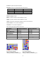
2.1.1 Technical Specifications
Model
Size
Resolution
(W X H in pixels)
Display type
Colors
Touch screen Type
Active display area
(W X H mm)
Display position
MTBF back light at 25 0C
Backlight
Brightness Adjustment
Screen Saver
Language Fonts
HMI 4.3”
HMI 7”
HMI 7” (HIGH
(LOW COST) PERFORMANCE)
4.3"
480 x 272
7"
800 x 480
7"
800 x 480
TFT, Wide
touch Screen
65,536
Resistive
analog
95 X 54
TFT, Wide
touch Screen
65,536
Resistive
analog
152 X 91
TFT, Wide touch
Screen
65,536
Resistive analog
Both horizontal Both horizontal
& vertical
& vertical
152 X 91
Both horizontal &
vertical
30,000 hrs
LED
Yes
Yes
Yes
50,000 hrs
LED
Yes
Yes
Yes
50,000 hrs
LED
Yes
Yes
Yes
Processor, CPU speed
ARM CortexA8, 667Mhz
ARM CortexA8, 667Mhz
ARM Cortex-A8,
1GHz
Flash Memory(ROM)
SDRAM(RAM)
Operating system
Real Time Clock
Buzzer
Sound Output
SD card slot
Communication
ports/Interfaces
RS232C, DB9 Male
RS232C/ RS422/
RS485, DB25 Female
Ethernet 10/100 Mbps,
RJ45
USB Host
128 MB
128 MB
WinCE 6.0
Yes
Yes
N.A
Option
128 MB
128 MB
WinCE 6.0
Yes
Yes
N.A
Option
1
1
HMI 10”
HMI 15”
10"
15"
1024 x 768 1024 x 768
TFT touch
screen
65,536
Resistive
analog
203 X 152
TFT touch
screen
65,536
Resistive
analog
304 X 228
Both
Both
horizontal & horizontal &
vertical
vertical
50,000 hrs 50,000 hrs
LED
CCFL
Yes
Yes
Yes
Yes
Yes
Yes
Main Hardware
128 MB
256 MB
WinCE 6.0
Yes
Yes
Option
Yes
ARM
Cortex-A8,
1GHZ
128 MB
256 MB
WinCE 6.0
Yes
Yes
Option
Yes
ARM
Cortex-A8,
1GHz
128 MB
256 MB
WinCE 6.0
Yes
Yes
Option
Yes
1
1
1
1
1
1
1
1
Option
Option
1
2
2
1
1
1
1
1
13
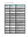
Model
Other networks
(Slave)
PROFIBUS DP,
PROFINET IO
DeviceNet,
EtherNet/IP
CANopen,
EtherCAT
General
specifications
HMI 4.3”
HMI 7”
(LOW
COST)
Option
N.A
Option
Option
Option
Option
N.A
Option
Option
Option
Option
N.A
Option
Option
Option
HMI 7” (HIGH
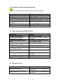
PERFORMANCE) HMI 10”
24 V DC
Rated Voltage
Power supply
24 V DC, 24 V DC, 110/220V
110/220V
AC
AC
11-36V DC 11-36V DC, 11-36V DC, 9090-250V
250V AC
AC
0.91A (DC) 1.09A (DC),
1.18 A(DC),
0.27A (AC)
0.29A(AC)
10 W
12W
13W
Rated Current
Power
Consumption
(with out sound
output)
Power on LED
Yes
N.A
indicator
Outer
140 X 116 X 212 X 156
dimensions
57
X 57
(W X H X D mm)
Mounting depth
51
51
(mm)
123+1 X 99+1 197+1 X
Panel cut (W X
+1
141
H mm)
IP65 front, IP65 front,
IP20 rear
IP20 rear
Protection
Plastic,
Plastic,
Front bezel,
plastic
plastic
housing
Stainless Steel
N.A
N.A
front bezel
(Option)
Panel
Panel
Installation
Mount
Mount
0.5
1.2
Net Weight (Kg)
Yes
212 X 156 X 57
24 V DC,
24 V DC,
110/220V 110/220V
AC
AC
11-36V DC, 11-36V
90-250V AC DC, 90250V AC
1.36A (DC), 2.46A(DC)
0.33A(AC) , 0.6A(AC)
15W
27W
Yes
Yes
325 X 263 X 400 X 310
56
X 56
51
50
50
197+1 X 141+1
310+1 X
+1
248
367+1 X
+1
289
IP65 front, IP20
rear
Aluminum, plastic
Option, IP66K
Panel Mount
1.4
14
HMI 15”
IP65 front, IP65 front,
IP20 rear IP20 rear
Aluminum, Aluminum,
metal
metal
Option,
Option,
IP66K
IP66K
Panel
Mount
3.6
Panel
Mount
5.1
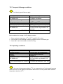
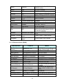
2.1.2 Serial drivers (COM1/COM2)
PLC/Inverter
Manufacturer
Protocol
Allen Bradley
DF1 protocol
Allen Bradley
DH485
Model
SLC 500 series, Micrologix,
CompactLogix, ControlLogix, PLC5
series
SLC 500 series, Micrologix
FC series for Automation
driver/HVAC drive
DVP-ES,DVP-EX,DVP-SS,DVPSA,DVP-SX,DVP-SC,DVP-EH,DVPEH2, DVP-SV,DVP-PM
Danfoss (Inverter) FC protocol
Delta
DVP serial
Fatek
Fatek
FB series
Festo
CI Command
FEC series
Fuji
T-Link protocol
Koyo
Micrex- F series
SPH 200, SPH 300, SPH 300EX,
Micrex Series protocol
SPH 2000
Series Ninety protocol Micro PLC,GE 90-30/ 90-70, Versa
(SNP)
Max
Micro PLC,GE 90-30/ 90-70, Versa
SNP-X protocol
Max
Micro EH, EH, EHV & H series
Hitachi Hi protocol
PLC's
MicroSmart, OpenNet Controller,
Data Link
Micro3
Direct Net
DL05, 06, 105, 205, 305 & 405
Koyo
K Sequence
Keyence
ASCII
Lenze (Inverter)
LECOM
LG
LG Cnet
Matsushita
(Panasonic)
Mewtocol
Fuji
GE Fanuc
GE Fanuc
Hitachi
IDEC IZUMI
Modicon
Messung
Moeller
Mitsubishi
DL05, 06, 105, 205 & 405 series
KV 700, KV1000, KV3000 &
KV5000
8200/9300 Vector, 9300 servo
controller, 9300 Servo PLC, Driver
PLC, 8200 Motec
GM series, MK series-K80S, K120S,
K200S, K300S, K1000S, XGB &
XGK series
FP series-FP0, FP2, FP-X, FPSigma, FP2SH
Modbus ASCII, RTU
Master
Modbus RTU
CanOpen
Melsec
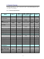
15
Any device
Nextgen 2000, 5000 series
XC100, XC200 series (Via Canopen
option converter)
FX, A, QnA & Q series, FX direct
CPU port
CV, CVMX, CX, CH, CS, CJ,
CQM1H series
CP, CS, CJ series
Omron
HostLink
Omron
Fins
Siemens
PPI
Siemens
MPI
Schneider
Toshiba
UniTeleway
Computer link,T series
S2E/ST2 series
serial
T1-micro series serial T1-Micro
Teco
Modbus
TP03 M/H, 14/20 SR, 26/36 SR
TecoInverter
Modbus
7200 MA, 7300 CV
Vigor
Vigor Serial
Vipa
MPI
Yaskawa
Memobus- MP Serial
M, VB, VH series
100V, 200V, 300V, 300S, 500S (Via
6ES7 972-OCA23-OXAO, RS232
To MPI/DP adopter)
Memocon, MP-900 & MP-2000
series
Toshiba
Yaskawa (Inverter)
Yokogawa
S7-200
S7-300/400 (Via 6ES7 972-OCA23OXAO, RS232 To MPI/DP adopter)
TSX-Micro & TSX series
Memobus-Inverter
serial
Factory Ace FA-M3
serial
F1000, V1000, T1000, A1000
FA-M3 model F3SPX series
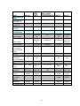
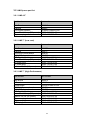
2.1.3 Ethernet drivers (RJ45)
Manufacturer
Allen Bradley
Ethernet
Beckhoff Ethernet
Protocol
Model
Ethernet/IP, CIP
SLC 500, Micrologix, Compact
Logix, Control Logix, PLC5
Beckhoff Ethernet
CX90X0 & CX10X0
Delta Ethernet
Delta Ethernet Protocol
Fatek Ethernet
Fatek Ethernet
DVP-SV series
FB series
Festo-Ethernet
Ethernet CI Command
GE Ethernet
SRTP
Hitachi Ethernet
H series Ethernet
Koyo Ethernet
Direct ECOM
Keyence Ethernet
Keyence Ethernet
LG Ethernet
LG Fast Ethernet
Modicon
Modbus TCP Master
Mitsubishi Ethernet
A, Q, QnA & FX Ethernet
Any device
A, Q, QnA & FX series PLC
Omron Ethernet
FINS UDP
CH, CS & CJ Series
16
FEC series
GE 90-30/ 90-70, Versa Max
EH, EHV and H series PLC
DL05,06, 205, 405
KV 700, KV1000, KV3000 &
KV5000
GM series, MK series 200S,
300S, 1000S, XGB & XGK
series
Siemens S7 Ethernet Siemens TCP/IP
Toshiba Ethernet
Toshiba Ethernet
Vipa
TCP/IP
Yaskawa MP Ethernet Memobus Ethernet
Yokogawa Ethernet
S7-200,300, 400 (Connection
Via CP card at PLC), S7-1200
T series, V series
200V, 300 S, 500 S
MP-900 & MP- 2000 series
Yokogawa FA-M3 Ethernet FA-M3 model F3SPX series
17
3. Ordering Code
3.1 HMI ordering code
HMI 4.3”
HMI 7”
1
0
0
0
0
0
(Low cost)
1
1
HMI 10”
1
1
HMI 15”
1
1
HMI 7”
(High Performance)
Power supply
Enclosure
1: 11 to 36V DC
2: 90 to 250 V AC
0: Standard
1: Stainless Steel
Sound Input, Output,
3 DI, 3DO
0: None
1: Yes
SD card slot
0: None
1: Yes
Ethernet
0: None
1: Yes
Other Networks (All Slaves )
0:
1:
2:
3:
4.
None
Profibus-DP
ProfiNet
DeviceNet
Ethernet/IP
5. CANopen
6: EtherCAT
8. CC-Link
Software
0: None
1: Free basic editing & data acquisition software HMI Editing Software
2: Extensive software HMI Editing Software Plus with Symbol Factory
3. No software, WinCE 6.0 core platform only
4. No software, WinCE 6.0 professional
18
3.2 HMI Spares part list
3.2.1 HMI 4.3”
Part Number
Part number
Main Board
IO Board
LCD Display Module
Power Fuse 4 Amp (DC power)
DC power plug
HMA045
HIO045
321MODU-LM0451-A0
10350-15402-01-00
10343-11027-00-00
3.2.2 HMI 7” (Low cost)
Part Number
Part number
Main Board
IO Board
90-250VAC power board
11-36VDC power board
LCD Display Module
Power Fuse 4 Amp (DC power)
DC power plug
AC power plug
Resistor 2.4/1w (AC power)
HMA073
HIO073
HPM751
HPM752
322MODU-LM0731-A0
10350-15402-01-00
10343-1103A-00-00
10343-1103A-01-00
10301-42409-55-00
3.2.3 HMI 7” (High Performance)
Part Number
Part number
Main Board
IO Board
Sound Board
90-250VAC power board
11-36VDC power board
LCD Display Module
Power Fuse 4 Amp (DC power)
Resistor 2.4/1w (AC power)
DC power plug
AC power plug
DI/DO plug
HMA075
HIO075
323PACK-SB0751-AO
HPM751
HPM752
323MODU-LM0751-A0
10350-15402-01-00
10301-42409-55-00
10343-1103A-00-00
10343-1103A-01-00
10343-1208B-00-00
19
3.2.4 HMI 10”
Part Number
Part number
Main Board
HMA105
Display Board
HDP105
Connection Board
HCB105
Sound Board
90-250VAC power board
11-36VDC power board
LCD Display Module
Power Fuse 4 Amp (DC power)
Resistor 2.4/1w (AC power)
DC power plug
AC power plug
DI/DO plug
324PACK-SB1051-AO
HPM751
HPM752
324MODU-LM1051-A0
10350-15402-01-00
10301-42409-55-00
10343-1103A-00-00
10343-1103A-01-00
10343-1208B-00-00
3.2.5 HMI 15”
Part Number
Part number
Main Board
HMA155
Backlight Board
HBL155
Sound Board
90-250VAC power board
11-36VDC power board
LCD Display Module
Power Fuse 6.3 Amp (AC power)
Resistor 2.4/1w (AC power)
DC power plug
AC power plug
DI/DO plug
325PACK-SB1551-AO
HPM751
HPM754
325MODU-LM1551-A0
10350-15632-01-00
10301-42409-55-00
10343-1103A-00-00
10343-1103A-01-00
10343-1208B-00-00
It is possible to change power supply from AC to DC and vice versa (Except HMI
4.3”) by replacing power supply board, after replacing power board, the label for marking
power input range located on the enclosure has to be changed.
20
3.3 Network option module part numbers
Option card
Part number
Profibus DP
ProfiNet
DeviceNet
Ethernet/IP
CANopen
EtherCat
CC-Link
Hnet-1
Hnet-2
Hnet-3
Hnet-4
Hnet-5
Hnet-6
Hnet-8
Table: Part number for network option modules.
3.4 Accessories part numbers
Part Number
WPG045
WPG073
WPG105
WPG155
HMB045
HMB073
Description
Gasket for HMI 4.3” (For dust and Moisture protection)
Gasket for HMI 7” (LOW COST)/ HMI 7” (HIGH
PERFORMANCE) (For dust and Moisture protection)
Gasket for HMI 10” (For dust and Moisture protection)
Gasket for HMI 15” (For dust and Moisture protection)
HMI Mounting Brackets (Metal Enclosures)
HMI Mounting Brackets (Plastic Enclosures)
3.5 PLC cables part numbers
For PLC to HMI cables and various connectors, please refer additional brochure “HMI
accessories”.
21
4. Installation
4.1 Installation
Guidelines
Stainless steel front HMI has sharp edges and more weight. Enough care should
be taken while inserting HMI into enclosure/panels using proper hand gloves. Improper
handing may cause injury personal during installation of HMI into enclosure/panels.
1. The HMI is intended for indoor use and not in any hazardous area.
2. HMI device should be installed in suitable enclosure/panels/cabinets/housings.
3. Avoid facing of HMI screen directly exposed to sun light.
4. Avoid installation in high vibration area/ moving parts.
5. Avoid installation near to high radiation/noise emitting devices like motors,
transformers, variable frequency drives, inverters, UPS, cellular towers etc.
6. Avoid installation in areas where there is the presence of vapors, gases, oils,
lubricants, chemicals etc.
7. Install HMI at suitable height and location which is easy accessible to operators.
8. When HMI is installed inside main panel, make sure that proper vents are available for
the main panel, ambient temperature inside the panel is not exceeded beyond HMI
specifications, operator is alerted incase of exceeding temperature limits.
9. When HMI is installed on panel front door, check depth of the HMI and make sure that
there is enough clearance available inside the panel after closing the main panel door.
10. A sufficient panel gage should be used in the main panel to firmly install HMI. Take
care when using stainless steel fronts as weight is heavy compared with alloy or
plastic fronts. Use rubber gaskets properly to achieve degree of Ingress Protection.
11. Use panel cut out as specified and firmly attach all mounting clips.
12. Maintain proper clearances around the HMI panel approx: 50 mm on all directions to
make sure that it is easy to remove HMI for maintenance purpose and temperature
dissipates by natural air cooling method.
13. Use proper line protections in power supply line via fuses, circuit breakers etc.
14. Connect earth properly to the HMI enclosures/panels/cabinets/housings.
15. Use proper cables, connect to ground properly before connecting power supply to HMI
16. Thoroughly check voltage levels accepted by HMI, measure voltage levels with a
multimeter before connecting them with HMI.
22
17. While using HMI with stainless steel front for wash down applications, make sure that
panels/enclosures/cabinets/housings are perfectly closed to avoid water entry inside
panels causing damages to the equipment and injury to operating personal.
18. Improper installation voids warranty.
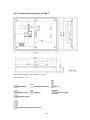
4.2 Dimensional drawings
4.2.1 Dimensional drawings of the HMI 4.3”
Note: All dimensions are in mm. Tolerance +/- 1 mm.
Panel cutout: 123
+1
X 99
+1
DB9, Male
DB25, Female
LAN, Ethernet (RJ45)
Network option
USB port
Power supply
23
SD slot
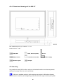
4.2.2 Dimensional drawings of the HMI 7”
Note: All dimensions are in mm. Tolerance +/- 1 mm
Panel cutout: 197
+1
X 141
+1
DB9, Male
LAN, Ethernet (RJ45)
DB25, Female
USB port
SD slot
Power supply
Network option
Terminals for DI/DO (future use)
24
4.2.3 Dimensional drawings of the HMI 10”
Note: All dimensions are in mm. Tolerance +/- 1 mm
Panel cutout: 310
+1
X 248
DB9, Male
DB25, Female
+1
LAN1, Ethernet (RJ45)
Network option
LAN2, Ethernet (RJ45)
25
Power supply
SD slot
USB port
4.2.4 Dimensional drawings of the HMI 15”
Note: All dimensions are in mm. Tolerance +/- 1 mm
Panel cutout: 367
+1
X 289
+1
DB9, Male
LAN1, Ethernet (RJ45)
DB25, Female
LAN2, Ethernet (RJ45)
Network option
USB port
SD slot
Power supply
4.3 Mounting
It is possible to insert HMI in either vertical or horizontal direction in enclosures/ panels/
cabinets/ housings. Panel cut out is as follows.
If HMI to be installed vertically, while creating new project in HMI editor software,
select resolution carefully at the beginning and then select the angle correctly during HMI
26
start up at the panel. Please refer section “Instrument” at “HMI startup” about how to
select angle for vertical installation.
Horizontal Installation
Model
Width (mm)
Height (mm)
Depth (mm)
HMI 4.3” HMI 7”
(Low Cost)
+1
+1
123
197
+1
+1
99
141
51
51
HMI 7” (High
Performance)
+1
197
+1
141
51
HMI 10”
+1
310
+1
248
50
HMI 15”
+1
367
+1
289
50
Vertical Installation
Model
HMI
4.3”
Height (mm)
Width (mm)
Depth (mm)
99
+1
123
51
+1
HMI 7”
(LOW
COST)
+1
141
+1
197
51
HMI 7” (HIGH
HMI 10”
PERFORMANCE)
+1
141
+1
197
51
HMI 4.3”
: 4 nos. mounting clips
HMI 7” (LOW COST)/HMI 7” (HIGH PERFORMANCE)
HMI 10”
: 10 nos. Mounting clips
HMI 15”
: 12 nos. Mounting clips
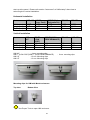
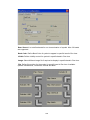
Mounting clips for HMI with Metal enclosures
Top view
Bottom View
Use Proper Tools to open HMI enclosure.
27
+1
248
+1
310
50
HMI 15”
+1
289
+1
367
50
: 6 nos. mounting clips
Mounting clips for HMI with Plastic enclosures
Top view
Bottom View
Tighten all mounting clips otherwise it may effect the touch panel operation and
ingress protection will be compromised.
The torque used for 4 sides of the housing should be balanced and not more than
1N-m (8.9Lb-in or 10.2 KgF-cm) to eliminate the LCD panel from bending.
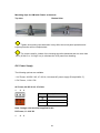
4.4 Power Supply
The following options are available.
1. AC Power, 90-250 V AC, 47~63 Hz, Universal AC power supply (Except HMI 4.3”)
2. DC Power, 11-36 V DC
AC Power, 90-250 V AC, 47~63Hz
1
2
3
Pin
Description
1
2
Earth
Neutral
3
Line
Note: Orange color terminal supplied for AC
DC Power, 11-36 V DC
1
2
3
28
Pin
Description
1
2
Earth
DC-
3
DC+
Note: Green color terminal supplied for DC
DC Power, 11-36 V DC (For HMI 4.3” only)
1
2
Pin
Description
1
2
DC +
DC -
Different power boards are available for above options and they will be fitted into HMI as
per ordering code.
The protective earth terminal should be connected first before any other
connection is made.
Do not open HMI enclosure in potentially explosive environments. If any service is
required, switch off the power supply and bring HMI to environment which is clean. Use
proper tools to open HMI enclosure. Repairs/servicing should be done by personal
qualified, trained, experienced and authorized to perform these kind of tasks. Dangerous
high voltages may be present in parts of PCB and improper servicing may cause shock
and fatal injury to personal involved in job.
All local electrical regulations should be strictly followed while connecting power
supply to HMI. Use proper rated cables, earth, grounding, shielding from reliable sources,
line protections in power supply circuit via fuses etc, to avoid shock, injury/death to
operating personal.
It is advised to use uninterrupted regulated power supply with adequate protections
and filters in power supply line to be used with HMI.
The plug-in terminal block for connecting the power supply is supplied along with
HMI and is designed for cables with a maximum cross-section of 1.5 mm2.
29
4.5 Interfaces
Tighten all the screws after inserting connector at COM1/COM2, otherwise,
communication failure with connected PLC/Inverter devices may occur because of loose
connections.
Refer OPC server manual for connection diagram between HMI and various PLC’s.
Every PLC may have different connector types, different pins are used for RS232C.
Improper cable/connections may damage either HMI or connected PLC.
Do not attempt to connect two different PLC’s manufacturers at a time on
COM1/COM2 port unless they support the same protocol like Modbus RTU.
COM ports are used for connecting with various PLC’s. It is not used for
downloading application or firmware from PC to HMI.
4.5.1 COM1 port, DB9 male (RS232C)
Fig: DB9 male
Pin
number
1
2
3
4
5
6
7
8
9
Signal
Signal Name
DCD
RD
TD
DTR
SG
DSR
RTS
CTS
RI
Data carrier detect
Receive data
Transmit data
Data terminal ready
Signal Ground
Data set ready
Request to send
Clear to send
Ring Indicator
Signal
Direction
Output
Input
Output
Output
Input
Output
Input
Input
Commentary note:
Please refer OPC Server user manuals for wiring connection between HMI and PLC
30
4.5.2 COM2 port, DB25 Female (RS232C/RS422/RS485)
Fig: DB25 female
Pin
number
Signal
Signal Name
Signal
Direction
Type
1
2
3
4
FG
TD
RD
RTS
Output
Input
Output
RS232C
RS232C
RS232C
5
6
7
8
CTS
DSR
SG
DCD
Input
Input
Output
RS232C
RS232C
5V-/RS232C
RS232C
9
10
11
12
13
14
TXDA
TXDB
RTSA
Output
Output
Output
RS422/RS485
RS422/RS485
RS422
15
RTSB
Output
RS422
16
17
18
19
20
CTSA
CTSB
DTR
Input
Input
Output
RS422
RS422
RS232C
21
5V+
Output
-
22
23
24
25
RI
RXDA
RXDB
Frame Ground
Transmit data
Receive data
Request to
send
Clear to send
Data set ready
Signal Ground
Data carrier
detect
Transmit data
Transmit data
Request to
send
Request to
send
Clear to send
Clear to send
Data terminal
ready
5 V Power
supply +
Ring Indicator
Receive data
Receive data
Input
Input
Input
RS232C
RS422
RS422
Commentary note:
Please refer OPC Server user manuals for wiring connection between HMI and PLC
31
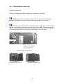
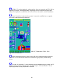
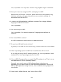
4.5.3 COM3 (Network option card)
Supported Networks:
Profibus, ProfiNet, DeviceNet, Ethernet/IP, CANopen , EtherCat
HMI will act as a slave with network option. PLC or external device should be
configured as master to communicate with HMI acting as slave in the network.
The above options are available for all HMI except low cost HMI 7” (LOW COST). At
any time, it is possible to insert only one of above module in HMI. It needs to open HMI
enclosure to change module from one type to another. Please insert the module properly
in the connector and make sure direction is proper and it is inserted firmly.
Fig: Main board, PCB inside HMI
Fig: Option card Top view
Fig: Option card Rear view
32
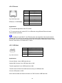
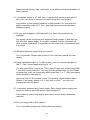
4.5.4 Ethernet
Fig: RJ45 connector
Ethernet, 10/100 Mbps
Pin
Description
1
2
Transmit (TX+)
Transmit (TX -)
3
Receive (RX+)
4
No connection
5
No connection
6
Receive (RX-)
7
8
No connection
No connection
Applications
a) To download application from PC to HMI.
b) To communicate with various PLC’s via Ethernet using different Ethernet based
communication protocols.
For HMI 10” and HMI 15”, two Ethernet ports are supported. One may be used to
connect with PLC devices for process control and data logging applications and another
port may be used for commercial applications like connection to local area network (LAN),
internet, Web server, IP Camera etc. in future.
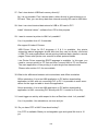
4.5.5 USB Host
Fig: USB connector
Pin
Description
1
2
+ 5V DC (max 500 mA)
USB-DN
3
USB-DP
4
GND
Applications
Connect Mouse, Insert USB flash disk etc.
Update HMI firmware from USB flash disk to HMI.
Transfer application from USB flash disk to HMI.
Transfer historical data from HMI internal memory to USB flash disk.
Connect USB printer to HMI
Save Historical data and Historical Alarms in CSV format to USB flash disk
33
Use only USB flash disk recommended by manufacturer. Make sure that no virus
is present in USB flash disk.
4.5.6 SD slot
Applications
It is used to store large volumes of historical data. All the data stored in SD card will be in
proprietary format for data security reasons. It requires historical viewer software to import
data from SD card and then archive historical data in PC. For compatibility reasons, we
advice to use SANDISK make SD card tested till 32 GB.
Use only SD card recommended by manufacturer.
4.5.7 Sound input/Output
Sound Input: It is to connect Microphone. (Reserved to use in future)
Sound Output: It is to play audio files on trigger of Event/Alarm
Sound input/output connector: Use 3.5mm diameter with 14mm length stereo phone plug.
34
HMI may be used to alert operators for process alarm conditions. These alarms
are intended for indication and taking preventive action only and they should be not used
as main source to safeguard operating personal and equipment. Do not use HMI for
emergency applications.
Note: Sound input, Output, 3 DI and 3 DO are available in same card
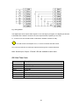
4.5.8 Digital input/Digital output
Digital Input: 3 nos. Digital inputs are available on board in sound input/output option card.
System tags available for digital inputs namely SystemD1_1, SystemDI_2 & SystemDI_3
Digital Output: 3 nos. digital outputs are available on board in sound input/output option
card. System tags available for digital outputs namely SystemDO_1, SystemDO_2 &
SystemDO_3
Pin
Description
Details
System tag
1
2
24V +
EIN1
Power supply + 24V DC
Digital input 1
N.A
SystemDI_1
3
EIN2
Digital input 2
SystemDI_2
4
EIN3
Digital input 3
SystemDI_3
5
ALM1
Digital Output 1
SystemDO_1
6
ALM2
Digital Output 2
SystemDO_2
7
8
ALM3
GND
Digital Output 3
Power supply + 0 V DC
SystemDO_3
N.A
Table: Pin connection details
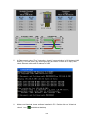
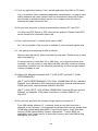
35
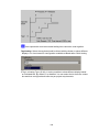
Fig: Wiring details
The digital input can accept a switch signal or a 24 volts logic input signal. The digital input function
is activated as the switch is closed or the event input terminal is pulled up to 24 volts.
L1, L2 and L3 can be a resistive load or inductance load like a buzzer or relay.
The total current consumption for L1, L2 and L3 must be less than 10mA.
VO1, VO2 and VO3 are 24 volts logic outputs for driving PLC or external devices.
Note: Sound input, Output, 3 DI and 3 DO are available in same card
4.6 Real Time Clock
Item
Description
Make
Model
Rating
Typical life time
Buffer period
Type
Accuracy
Seiko Instruments
MS621-FL11E
3V/4 mAH
10 yrs
6 months
Rechargeable
Maximum +/- 2 sec/day
36
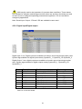
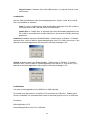
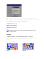
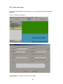
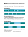
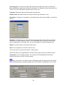
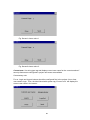
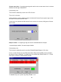
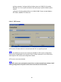
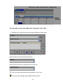
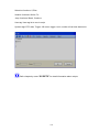
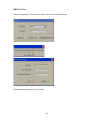
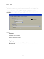
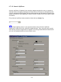
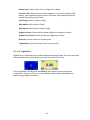
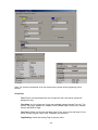
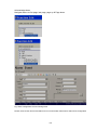
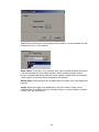
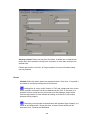
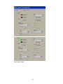
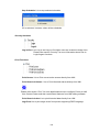
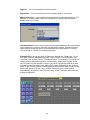
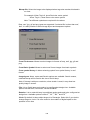
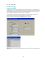
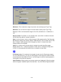
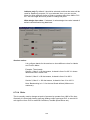
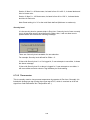
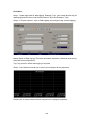
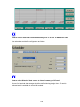
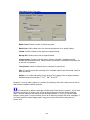
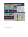
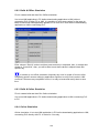
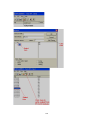
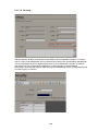
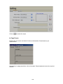
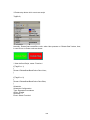
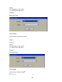
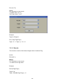
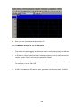
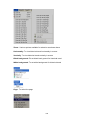
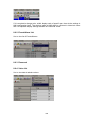
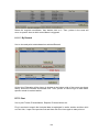
4.7 HMI Reset Procedure
For All models:
Formatting from HMI
Short Pin 2 & 3 in Com2
Power ON the HMI
HMI Screen will be shows like below
37
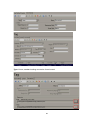
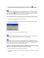
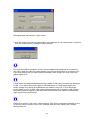
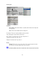
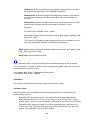
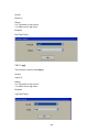
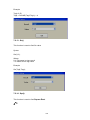
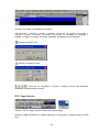
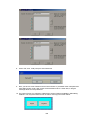
Formatting is to format the project and data in the HMI
Press the format button to Format
After Formatting, it is needed to calibrate the touch screen
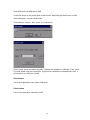
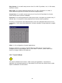
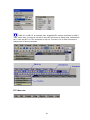
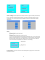
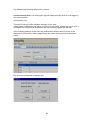
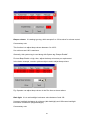
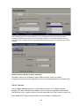
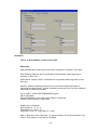
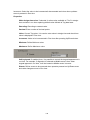
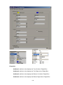
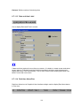
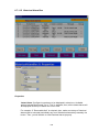
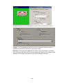
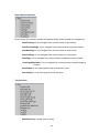
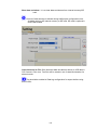
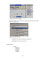
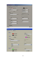
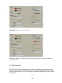
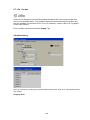
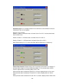
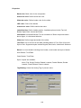
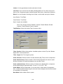
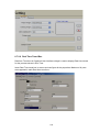
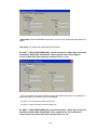
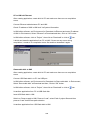
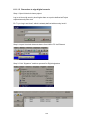
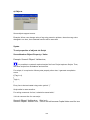
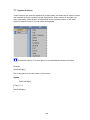
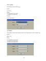
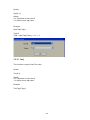
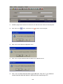
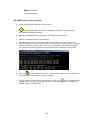
Upgrading the firmware
By using SD Card
Short pin 2 & 3 in Com2
Insert SD Card with the firmware. The SD Card must be formatted to FAT32
Power On HMI
The Screen will Appear like below
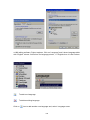
38
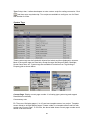
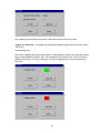
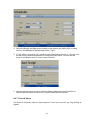
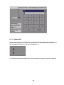
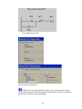
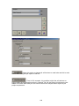
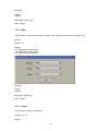
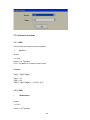
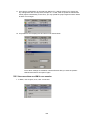
Press Upgrade Button for 3 Seconds
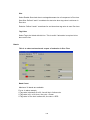
The upgrade Process Starts
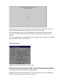
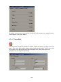
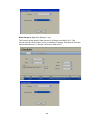
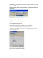
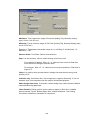
After Completing the Upgrade The screen will appear like below
Then it is needed to calibrate the touch screens
39
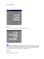
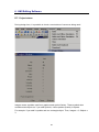
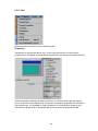
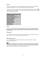
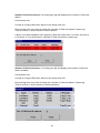
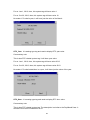
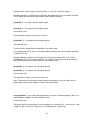
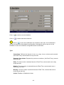
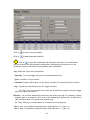
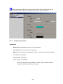
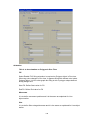
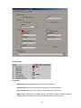
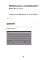
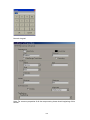
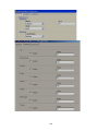
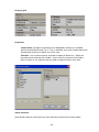
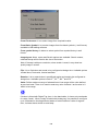
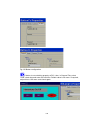
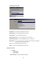
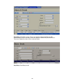
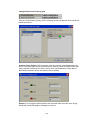
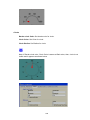
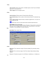
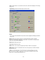
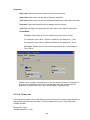
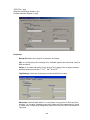
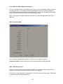
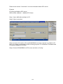
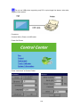
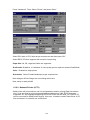
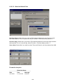
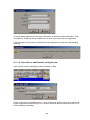
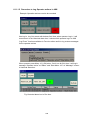
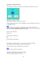
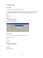
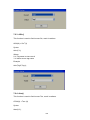
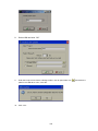
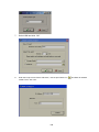
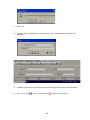
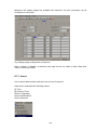
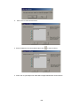
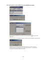
By Using USB:
Insert USB with Updated Firmware in the USB Port of HMI
Go to Control Center
Select System Information
Select Update Button to Update. This will update the firmware in HMI.
40
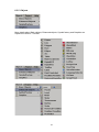
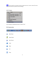
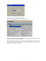
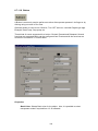
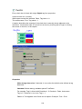
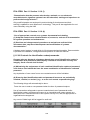
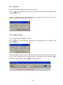
5. Software
5.1 PC Software
HMI Editing Software is Basic HMI Editing software
HMI Editing Software Plus is Extensive HMI editing Software with Symbol Factory
Historical Viewer software is to view historical data via PC
5.1.1 Basic software - HMI Editing Software
It is HMI editing software to develop applications in HMI. It is mainly used for application
development useful for operator interface in industrial applications. Using HMI, operators
will be able to communicate with PLC’s, Inverters etc. using OPC server via COM port and
Ethernet port on different kind of protocols. Using HMI editor software, it is possible to
develop operator interface applications like the following.
Sending start/stop command from HMI to PLC to start motors, pumps etc.
Display running stats of motors, pumps etc.
Display Real time value of process parameters like temperature, flow, pressure etc
Visualize process data in meaningful way as bar graphs, real time trends, historical trends,
dial, meter, level, digital LED etc.
Real time alarms, historical alarms, alarm management.
Recipe management, scripts programming
Animation like visibility control, blinking, horizontal movement, vertical movement etc
Scheduler with timers, counters, totalizers etc
Data logging, different log methods, security, multi language etc
HMI Editing Software contains basic symbols in various categories. Please refer
section by name “Graphics” for more details about basic symbols.
5.1.2 Extensive software - HMI Editing Software Plus
HMI Editing Software Plus is Extensive Software with Symbol Factory
control. It is
an option.
It contains all the features of HMI Editing Software + Symbol factory.
Symbol factory contains thousands of symbols for many industrial applications. All the
symbols are objects, allowing changing colors in run time based on tag value occupy less
memory and do not loose quality of symbol on enlargement.
Please refer section “Symbol Factory” for more information about this topic.
41
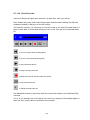
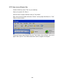
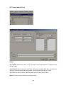
5.1.3 Historical viewer
Historical viewer is a data acquisition software tool to view historical data via PC. It is
supplied free along with both HMI Editing Software and HMI Editing Software Plus.
If Data logging is configured, then it stores historical data first in HMI internal memory or
optional SD card (In selective HMI models) in proprietary format for data security reasons.
This data can be dumped into USB flash, imported to PC via historical viewer and then
archive historical data in user friendly formats.
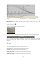
Historical viewer in DAQ has following features.
Historical trend
Historical Alarms/Events
Display Historical values in tabular column.
Search data by Time, Timer Period, Event/Alarm, tag wise and Remark
View trends both horizontally and vertically
Zoom out & Zoom In
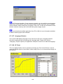
Display view options available at 1 sec/dot, 2 sec/dot, 5 sec/dot, 10 sec/dot, 20
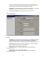
sec/dot, 30 sec/dot, 1 min/dot, 2 min/dot, 5 min/dot, 10 min/dot, 30 min/dot, 10
min/page, 30 min/page, 1 hr/page, 2 hr/page, 4 hr/page, 8 hrs/page, day/page,
week/page and month/page.
Display white back ground/black background.
Export data and alarms/events to CSV files. (Specify time or time period or all).
Print trend view, Event/Alarm list & Tag Values.
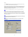
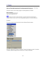
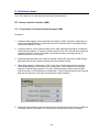
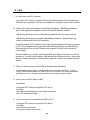
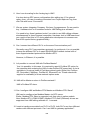
5.1.4 System Requirements
PC with Minimum 1GHz processor, 1GB RAM (Minimum), 2 GB preferred
500 MB free space in the hard disk
Minimum 20% free space in hard disk, Less than 10% space generates error message
Ethernet Network adopter RJ 45 female
RS 232 serial port, RS485/RS232 converter to check online simulation if required
USB host to insert USB flash disk
Screen resolution better than 1024 X 768 (For HMI 10” and 1550 projects)
Display font size (control panel->personal->display->font size) is to be default size.
42
Operating system: Windows XP, Windows Vista, Windows 7, Windows 2000 & Windows
2003 Server
5.1.5 Software Installation
Install Microsoft installer V3.1
Install Microsoft.Net frame work V3.5 SP1
Install HMI Editing Software
Install OPC server
Install Demo projects
Install Historical viewer
Install Remote viewer
5.1.6 Accessories
AC/DC power supply, preferably un-interrupted power supply (UPS)
PC to HMI programming cable (Ethernet)
USB stick
Pen for easy touch operations
Power supply connectors
5.1.7 Quick start
Install Microsoft.net, HMI Editing Software & OPC server software in PC.
Open HMI Editing Software in PC
Create a new project and develop a sample application.
Build project. If any errors, correct them
Save project
Check project in offline simulation
If PLC is being used for testing, then
43
Make sure that appropriate program is available at PLC
Check OPC server manual for specific PLC driver and prepare correct cable
Configure OPC server properly in HMI Editing Software and create PLC data base
Connect PLC to HMI cable, make sure correct COM port is connected as per configuration
Power on PLC, connect power supply to HMI and power on HMI
Connect Ethernet cable between PC and HMI and download project from PC to HMI.
Check section 6.8.7 for more detailed information how to download project
Run the application in HMI
5.2 HMI firmware
HMI firmware installed in HMI
HMI will be loaded with firmware at factory, then, on power on, HMI will display start up
screen. It is possible for users to update firmware later via USB flash disk. You can find
firmware version information in HMI itself. Hold touch area in HMI, power on, then on start
up, press on “System information” to display firmware version number. Please contact the
manufacturer/distributor/supplier for latest firmware updates.
Refer section “HMI Startup” for more details about HMI firmware. It is mainly used for
operation and maintenance purpose including loading application, running application,
calibration of touch screen, Setting clock, Setting IP address, adjusting beeper volume,
back light, screen saver time, setting angle of orientation as per mounting etc..
5.2.1 HMI startup
WinCE 6.0 operating system is preinstalled in all HMI devices.
After power on, initial HMI screen is as follows
44
5.2.2 Run
It is to run application in HMI device. After receiving application from PC via Ethernet or
USB stick, press on “RUN” soft button to run application in HMI
5.2.3 Project
It is to configure how to execute application
Power On execution
Available options are Run project and Control center
Project: If selected, then, after HMI power on it directly runs project automatically.
45
Control Center: If selected, then, after HMI powers on, it stays at Control center,
initial screen.
Load action
Set how HMI should behave after downloading application. Option “Load” and “Load &
Run” are available for selection.
Load: If “Load” is selected, then after downloading application from PC to HMI or
removable disk to HMI, HMI will remain at initial screen.
Load & Run: If “Load & Run” is selected, then after downloading application from
PC to HMI or removable disk to HMI, HMI will run and execute recently download
application.
Download: Available options are Enable/Disable. Default action is “Enable”. If “Disable”
selected, then, it will not allow to download application from PC to HMI. At this time, if any
attempt to download application, will prompt the following message in PC
Upload: Available options are Enable/Disable. Default action is “Enable”. If “Disable”
selected, then, it will not allow to upload application from HMI to PC. At this time, if any
attempt to download application, will prompt the following message in PC
Load button
It is used to load application from USB stick to HMI manually.
First make sure that project is compiled in PC and stored on USB stick. Please check
section “Download” for information about how to download project from PC to USB stick.
Procedure:
Build application in PC
Download application from PC to USB stick
46
Insert USB stick into USB port in HMI
Touch with finger on any active area in HMI screen, hold the finger and Power on HMI.
After loading bar, it shows initial screen
Then press on “Project”, then, press on “Load button”
Press “Down” arrow and select the path, if folders are available in USB stick. Then, press
on “Load” button near the combo box. If project file is available in selected path, then, it
will transfer from USB stick to HMI.
Save button
It is to save application from HMI to USB stick
Clear button
It is to clear application manually in HMI
47
5.2.4 Instrument
Clock:
It is to set Date Format, Date, Time Format and Time in HMI
If earlier loaded application using data logging, then, before setting clock, it requires
to transfer historical data and alarms from internal memory/SD card to safe place say USB
stick or transfer to PC via Ethernet. Other wise, you may loose historical data and alarms
in internal memory/SD card permanently after changing the clock
Ethernet:
It is to define IP address to HMI
48
Type: Available options are static and dynamic. If dynamic is selected, then, address,
mask and gateway are disabled and they will be assigned by DHCP server automatically.
If it is static, then, user can set IP address for HMI manually
Address: IP address of HMI
Mask: Subnet mask address
Gateway: Gateway address
If HMI is connected with LAN, contact system administrator to allot unique IP
address for HMI in network
Orientation:
O
O
By default, it is Angle: 0 , other available options are 90 , 180
O
& 270
O
Angle 0 O and 180 O are for horizontal installation, Angle 90 O and 270 O for vertical
installation.
Horizontal Installation
Angle 0
O
Angle 180
49
O
Vertical Installation
Angle 90 O
Angle 270 O
The given examples are for illustration only. In practice, if you create a project with
horizontal installation and then select Angle 90 O, then, you may not be able to see full
screen properly in HMI. For vertical installation, it requires first to select the resolution
properly while creating a new project in HMI editor software and then select the same at
HMI startup.
HMI 7” (HIGH PERFORMANCE) project
Project creation: Horizontal resolution
O
Orientation: Angle 0
50
HMI 7” (HIGH PERFORMANCE) project
Project creation: Horizontal resolution
Orientation: Angle 90 O
Language: It is to select language for the Control center. By default, it is English.
Possible language options include Simplified Chinese, Traditional Chinese, Japanese,
French, German, Italian, Polish, Spanish, Portuguese, Russian, Thai, Czech, Danish,
Dutch, Korean, Swedish and Turkish
Advanced setting:
51
Beep Volume: It is to define beep volume from 5 to 100%. By default, it is 10. 100 means,
maximum volume
Back Light: It is to define backlight setting from 5 to 100%. By default, it is 100%. 5
means less back light and you cannot see screen images properly.
Screen Saver: It is to define screen saver in min. from 0 to 60. By default it is 0 which
means screen saver function is disabled.
Password: It is to define password for HMI control center. It accepts only numeric entry. If
defined, then, it is required to enter password for all control center operations.
First time, it is required to enter password twice, first one is password and next one is for
confirmation. If user enter wrong password, it shows message “Wrong password, try again
please”.
Other: It is for configuration of special applications.
Example: TwinCAT, to configure TwinCAT Ethernet OPC server, it need to setup
configuration at Control center as well. For this, select “TwinCAT”, press “Other” soft
button to configure AMS net ID details etc.
5.2.5 Touch Calibrate
It is used to calibrate touch screen. While running the application, if soft button in
application is not sensed properly or if boundaries of soft button are shifted, then it might
require recalibration of touch screen.
52
Initially target will be at center. Carefully press and briefly hold stylus on the center of the
target. Repeat this procedure as target moves around all the 4 corners.
After completing above step, it prompts message “New calibration settings have been
measured”. Press the enter key (touch with finger any screen area) to accept the new
settings.
Avoid operating with hard or sharp material such as ball point pen or pencil, use polyacetal
pen (stylus tip 0.8 mm or less) if possible.
5.2.6 System Info
Version: Shows current firmware version of HMI
Flash: It shows internal memory status in MB. First one indicates free memory available
for use and second one represents total memory capacity. 32 MB reserved for system. So,
remaining can be used for application and data logging.
SD card: It shows SD card memory status. First one indicates free memory available for
use and second one represents total memory capacity.
53
USB disk: It shows USB stick memory status. First one indicates free memory available
for use and second one represents total memory capacity.
IP/MAC: Display IP address and MAC address of HMI
Update: soft button used to update firmware in HMI.
5.2.6.1 Firmware update procedure
1.
Please check current firmware version in your HMI. Power on HMI. At control
center, touch soft button “System information” and note down current firmware
version
2.
Obtain latest firmware files from factory. There are different firmware files for
different HMI models and please use correct file to update firmware in your HMI.
Model
Firmware
version
0.99B1/0.99B2
to V1.0
0.99B3 or later
to 1.27
1.30 to Latest
Version
HMI 4.3”/
HMI 7”
(LOW COST)
Img.bin(6410)
folder- unzip to get
IMG.BIN file
HMI 7” (HIGH
PERFORMANCE)
/ HMI 10” / HMI
15”
Img.bin(PC100)
folder-Unzip to get
IMG.BIN file
HMI 7” (HIGH
PERFORMANCE)
/ HMI 10” / HMI
15” (1Ghz CPU)
Not applicable
HMI_6410.BIN
HMI_PC100.BIN
HMI_PV210.BIN
HMI_PC100.BIN
HMI_PV210.BIN
HMI_PV210.BIN
3.
Make sure USB stick is empty
4.
Copy firmware update file to USB stick directly to root path (do not keep
firmware file in any folder)
5.
Insert USB stick into HMI
6.
Power on HMI
7.
In Control center, Press “System information”.
Note: In case if HMI is not going to Control center screen at power on
because of control center settings, hold finger on any touch area and then
power on HMI. Then, HMI will go to control center screen at Power on.
8.
Press “Update”
Then, follow on screen instructions.
Restart the HMI after firmware update procedure and perform Touch screen
calibration once.
Note: Do not power off HMI during firmware update process. Failure to do so
may corrupt files, needs to send HMI back to factory to restore
Note: After firmware update, it needs to download application again
54
6. HMI Editing Software
6.1 Project status
During design time, it is possible to check current status of resources being used
Images means symbols used from graphics and symbol factory. These symbols also
considered as objects so, if you add symbols, it also updates quantity in objects.
For example: If you add 2 symbols and one rectangle object. Then, Images = 2, Objects =
3
55
6.2 Create new project
Open HMI Editing Software from desktop icon or from Start-Programs-HMI Editing
Software
Click on “Create a new project”
Project Name: It is Name of Project. For ex: Boiler
56
Location: It is path for project file storage.
Resolution: Select the required HMI model and resolution
HMI size
Horizontal installation
Vertical Installation
4.3”
480 X 272
272 x 480
7” Low cost
800 x 480
480 x 800
7” High end
800 x 480
480 x 800
10”
1024 x 768
768 x 1024
15”
1024 x 768
768 x 1024
Note: HMI resolution should be selected properly when new project is created.
Default Language: English
Width: It is pixels, resolution in dots available on X-axis
Height: It is pixels, resolution in dots available on Y-axis
Author: Write author name/system integrator name for future reference
Version number: It is for version management
Comments: It is for project management
After entering all the above details, click at “OK”
Description
Horizontal Installation
Vertical Installation
HMI 4.3”
480 X 270
270 X 480
HMI 7” (LOW COST)
800 X 480
480 X 800
HMI 7” (HIGH
PERFORMANCE)
800 X 480
480 X 800
HMI 10”
1024 X 768
768 X 1024
HMI 15”
1024 X 768
768 X 1024
Orientation
O
0 or 180
Fig: Horizontal Installation
HMI 4.3”, Resolution: 480 X 270,
O
Orientation Selection at HMI start up 0
O
O
90 or 270
O
Fig: Vertical Installation
HMI 4.3”, Resolution: 480 X 270,
O
Orientation Selection at HMI start up 90
57
If HMI 4.3” is to be installed in vertical position, then, set resolution as 270 X 480 at
beginning of project, develop application accordingly and set orientation angle at HMI
startup. Once project is created with 480 X 270, it cannot be used for vertical installation.
Once, Resolution is selected for a project, it cannot be modified later or upgrade
this project to another project model/size.
HMI 10”, Resolution: 768 X 1024,
Fig: Vertical installation,
While creating new project, select correct HMI size, resolution properly based on
Horizontal or Vertical resolution and select orientation angle properly at HMI startup
screen.
For HMI 10” and HMI 15”, before creating vertical installation project, please set PC
monitor settings properly and make sure that page height = 1024 and Width = 768 are
displaying properly in page properties for screen1.
58
If HMI 10” or HMI 15” is selected, then, suggested PC monitor resolution is 1280 X
1024, other wise, you may be not able to see view full screen in design time. Alternatively,
set % view say 50 % or 75% as shown or click on “Full view” icon to view full screen in
design time for preview purpose.
6.3 Menu bar
59
6.3.1 File
New: To create a new project
Open Project: To open existing project
Close Project: To close present project
Save Project: To save Project in default path
Save Project As: To save project in selected path other than default path specified while
creating a new project settings.
Upload: To upload project from HMI back to PC
Recently: It is to open recently opened projects
Exit: To exit from current project
HMI Update: To update HMI firmware directly from PC via Ethernet.
Note: The best way is to update firmware via USB disk
60
Control Center: To update control center firmware. You need to get latest
firmware files from factory and save them in PC say Desktop.
First enter IP address of HMI at Environment settings in HMI editing software as
shown above, then, try to update firmware from PC to HMI via Ethernet
Click “HMI Update/Control Center
Press “Yes”
61
If you see “Download” message for long time, then, there might be problems to
clear project. In this case, restart HMI, press “Project” at Control Center. Then,
clear the project manually. Then, try to download firmware again
Language: To update language files in HMI. This is required only if new language
required at Control Center. Contact factory for further information
Clock Synchronization: To Synchronize HMI clock with PC Clock
6.3.1.1 Environment
General:
Language: Select Language for project environment. 18 languages are supported
from HMI editing software V1.1 onwards including English, Simplified Chinese,
Traditional Chinese, Japanese, French, German, Italian, Polish, Spanish,
Portuguese, Russian, Thai, Czech, Danish, Dutch, Korean, Swedish and Turkish
Environment font: Select font required for design time environment. Example:
Menu, Tool Box, Project explorer, function editor etc.
Project Path: Location to storage of project files
Default project path: C:\Program Files\HMI Editing Software\HMI Editing
Software\PanelProject
Graphic Path: Location of default basic Symbols
Default graphic path: C:\Program Files\HMI Editing Software\HMI Editing
Software\Basic Symbols
62
Security: This is to protect opening HMI editing software in specific Personal
computer (Not for project). Once password is entered, it is required to enter
password correctly to open HMI editing software for the current session. This is
useful in factory environment to prevent un- authorized users to open HMI editing
software.
Note: If you need password for specific project, then, click at “Settings” in project
explorer, select “General” tab and then enter the Password
Fig: Password for specific project
In general, it is preferred to take back up of project files regularly in other standard
storage media like CD, DVD etc. It is recommended to store project files in separate
folders at D: drive instead of C: drive. Developer may plan hard disk partition and save all
project files in drive other than location of operating system such that even if there are
problems with Operating system, still it is possible to retrieve project files.
Download and Upload: Please refer section “Project tools” for more detailed information
Snap and Grid: It is to define grid behavior in design time environment.
63
Grid: Select this option and select “Show grid” if grids are to be appeared in screen at
design time.
Snap lines: Select this option if grids are not required to appear in screen at design time.
Snap: Select this option if component coordinates should with in grids all the time.
Object: Define default font size, Fill color, Back color and Fore color for the properties of
most of the objects like label, Check box, Rectangle, Ellipse, Pie, Table, Dial, Level, Meter,
Slider, Thermometer etc.
64
6.3.2 Edit
6.3.3 Format
Align: It is to align selected components, objects etc. for adjusting their position precisely
in screen layout. Available options for selection are Center, Right, Left, Tops, middle &
Bottom.
Ex: Align two Labels to the left in HMI screen.
Assume both labels are created in Screen1. Select both the labels first using mouse,
alternatively, select first label by left click at mouse, then press “Ctrl” in keyboard and then
select second label by left click at mouse. Now, in Menu, click at “Format”, then select
“Align”, then select “Left”.
Before Align adjustment
After Left Align adjustment
65
Make Same Size: It is to adjust different objects to the same Width, Height, Both width
and height, Size to grid etc.
Ex: Adjust five buttons to same size i.e., height and width.
Create five buttons first say in Template. Then, select all these buttons via Mouse and
then click at “Format”, then select “Make same size”, then select “Both”
Before size adjustment
After Same Size adjustment
Horizontal spacing: It allows adjustment of horizontal spacing between any objects to
make Equal/Increase/Decrease/Remove.
For ex: There are 3 buttons located at bottom area of a page. Spaces between these
buttons are not equal and screen is not looking well. Now, select all the 3 buttons via
Mouse or using “Ctrl” in keyboard along with mouse and then in Menu bar, click at
“Format”, then select “Horizontal spacing”, then select “Make equal”. Now, it adjusts space
between all these buttons with equal distance.
Before Spacing adjustment
After Horizontal spacing adjustment
Vertical spacing: It allows adjustment of vertical spacing between any objects to make
Equal/Increase/Decrease/Remove
Before Spacing adjustment
After vertical spacing adjustment
66
Center in Page: It allows adjustment of objects center in page horizontally and vertically.
For ex: There are 3 buttons located at screen. You wish to locate them center in page
horizontally. Then, select these buttons and apply this feature to adjust buttons as per
requirement.
Order:
Bring to back: It take object back
Bring to Front: It take object to the front side
For ex: There is Rectangle box and a label with different colors. If you wish to keep
label text on Rectangle, then, for the Rectangle, choose the option, “Bring to Back”
and for the label, choose the option “Bring to Front” such that both are visible at
same time allowing overlapping of two objects for clear display.
Lock Controls: It is to lock control for further development. Apply this for a second time
to unlock the control.
67
6.3.4 View
Select the required items to view in window layout.
Properties
If properties is checked as above, then, in the right side bottom of screen layout,
properties box will appear showing all the properties for the component/object selected.
In above example, rectangle is drawn and once it is selected, then right side bottom
corner, it shows all the properties for this specific rectangle if properties are checked in
view at Menu bar. It is possible to modify properties of rectangle from property grid.
Alternatively, double click on Rectangle and enter the same at Graphical wizard.
68
Output
If output is selected in the view, this window appears just below the screen working area.
This window will display any errors that appear during compilation of project.
In Menu, click at “Tools” and then “Build” or alternatively, in standard bar, click at icon
to prepare build for the application. Then, project will compile and it shows summary in the
output window as shown below.
Zoom
It is to Zoom current screen to various % and it is useful during screen editing particularly
if screen size of PC screen is less. If 200% is used and if PC screen size is small, then
horizontal and vertical slider will appear automatically in screen to navigate to other areas
of screen easily.
Full screen
It is to display full screen and after selection, screen layout will be as shown below. To go
back, in menu, click at “View” and then “Full screen” again
Reset window layout
It is to display default screen layout showing screen working area, tool box, project
explorer, output window etc.
Ex: If user deselects project explorer at View, then it will not show Project explorer
at right side of the window layout. In this case, user may select Project explorer again at
View, alternatively, in Menu, click at “View” and then “Reset Window Layout”, then it will
reset all the view selections and show default window layout.
69
6.3.5 Objects
More details about Basic objects, Enhanced objects, Symbol factory and Graphics are
explained in section “Tool Box”
70
If you would like to increase font size in Menu bar, then, in menu, click at File, then
click at “Environment” and then set font settings.
6.3.6 Project
Above details are explained at section “Project Tools”
6.4 Standard bar
New Project
Open Project
Save Project
Undo
Redo
Cut
Copy
71
Paste
Delete
Search
Show Grid
Align to Grid
Build
Offline Simulator
Online Simulator
Stop simulation
Download
Full screen
6.5 Format bar
Bring to Front
Bring to Back
Lock the control
Group
Ungroup
Align left
72
Align center
Align right
Align Top
Align bottom
Align middle
Make same width
Make same height
Make same size
Size to grid
Make horizontal spacing equal
Increase horizontal spacing
Decrease horizontal spacing
Remove horizontal spacing
Make vertical spacing equal
Increase vertical spacing
Decrease vertical spacing
Remove vertical spacing
Center vertically
Center Horizontally
6.6 Project Explorer
73
6.6.1 Setting
Project Settings
General
While creating a new project, it requires user to enter Project Name, storage location,
selection of HMI model with resolution (Horizontal/vertical installation) etc. Some setting
like Project Name, storage location, resolution with width & height,Language cannot be
modified after creating project, others can be modified later.
Password: It is password for specific project. If defined, then, it is required to remember
carefully and it is prompted to enter password when specific project is opened in any PC.
74
Run Time
It is to select Data, Alarm log path, start up and shutdown expressions
Data log storage: Define data log storage path. Available options include internal
memory and optional SD card
Internal storage: Define internal storage path for Historical data and historical Alarms.
Available options include internal memory and optional SD card. SD card option is
available in selected HMI models. In case large internal memory is required, it need to
select SD card and in this case historical data and alarms are stored in SD card instead of
internal memory. How ever, retrieval of historical data and alarms from SD card may be
little bit slower compared with retrieval from internal memory.
Alarm sampling rate: Define sampling rate for alarms. Default sampling rate is 1000
msec. Range of sampling rate is from 100 msec. to 10,000 msec.
Start up Event: Define events to be executed during HMI power on.
For ex: User can write a script to be executed at HMI power on and these scripts can be
selected at start up expression. This feature is useful to initiate some values at register etc.
Ex: Tag1=10;
Shutdown Event: Define events to be executed before shutdown of HMI.
Project Start Image: Select the image to be displayed at HMI Power ON. Supported
formats include bmp, jpeg & Png. This image will be displayed in HMI after running the
application but before showing Screen1
Resource
This is to add list of audio files (.wav format) to play for selection later from Alarms/Events.
There are several audio files available in your PC at path C:\WINDOWS\Media
75
Please refer audio files functions in section “Function editor” for more information about
the functions available to use for audio features. Audio functions include “Play sound”
once/Loop and “Stop sound”.
This is to add Text fonts for the project.These fonts can be used in the texts on the Objects.
6.6.2 Screen
This is to add new screen to the project.
It is possible to set screen into following types
1. Page
2. Template
3. Popup
When new project is created, screen1 (Page type) is created by default. It is not possible
to change screen1 to either template or popup. Screen1 (start page) should be “Page”
type only.
How to add a new page
In Project explorer, select “Screen1”, then right click Mouse, then, it shows the screen
below. Click at “Add”, Screen2 will be created and appears as shown below.
76
Now, Select Screen1, and then check its properties. For ex: It is possible to change
background color of screen from the page properties
Right click mouse keeping pointer on any page, then, you can edit screen properties via
wizard.
77
It is possible either to open, delete or rename screen. Select screen, then “Right click” at
mouse to appear above dialog.
Note: These screen display names are same as available at project explorer. These
are different from title bar (Text) defined for screen
Properties:
Back Color: Define background color of component.
Events:
Activated: Define tasks to be executed before opening Screen.
78
Deactivated: Define tasks to be executed before closing Screen.
Screen Style
Page No: Display current page number.
Screen Height: Define/Display current screen height.
Screen Width: Define/Display current screen width.
Template: Select Template page for this screen.
Title bar: Control visibility of Title bar and select it in design time.
If Title bar = True selected in Page properties, then, number of grids
vertically in screen multiplied by grid size will not match with screen height as Title
bar occupies some space.
Type: Define type of screen. Available options include Template, Page and Popup.
Template
If some common labels/buttons are required in all the HMI screens, you may
customize template any time and these changes will be updated in all the screens
available in project dynamically. It is preferred to create a template at the beginning before
creating new pages such that you will know clearly about their location while designing
new pages. For one project, it is possible to have more than one template and then select
them in other pages.
It is to avoid duplication of work and save time.
If any page is created as template (except screen1), it is possible to link it with another
normal page.
Ex: Create Screen2 as template, then, insert common objects in screen2 like date, time,
page navigation buttons etc…Now in all other screens, select Template = Screen2 such
that all objects in screen 2 will appear in other screens. In this case, there is no need to
create date/time in every screen, just created once in screen2 and it is linked in other
screens.
Note: Screen1 should be Page type only. If you need Template or Popup, create a new
screen and then select the type accordingly.
79
Pop up
It is to pop up small screen with out closing current active screen.
Application: Operator may wish to monitor a bar graph of process value in small screen
when he press a button near process value.
Screen2 is defined as popup.
Screen height= 240, Screen width = 400
Now, it is possible to open screen2 from button.
6.6.3 Tag
Mainly there are two types of tags.
User defined Tags (PLC tags, networking tags and internal memory)
System Tags (Available by default)
User define Tags
It is a tag data base, containing internal memory, PLC tags & network tags (With network
option).
Click at
to add new internal memory tag.
80
Click at
to delete existing internal memory tag.
Note: To remove Tag created at OPC server, user is required to go to Connection, open
OPC server and delete the tag.
Click at
to save changes related to Internal memory tags.
If new tag is added to data base or modifications are done for any existing internal
memory tag, click on
to save the changes, other wise, click at any other Row in
available Tag list such that changes will be saved to data base automatically other wise,
changes will be lost.
It is to Copy and paste tags. Works fine with internal memory tags
It is to move up/down of tags. Works fine with internal memory tags
Name: It is Tag Name
Connection: HMI Internal memory or OPC server tags or devices connected externally
via network option.
Connections refers to Protocol selection for specific PLC that is to be connected at Serial
port or Ethernet port.
Type: Tag data type, available options for internal memory type tags are Digital, Analog
and String.
Scan mode: Automatic, Always, Active on page, None options are available for selection.
Automatic: By default, Tag is selected as Automatic scan mode from V1.20
Onwards
If the scan mode of the Tag selects the [automatic] mode, then, if you use the
functions [data log, Alarm , Script, scheduler, RealtimeTrendBox, startup event,
shutdown event ], then, [automatic] mode will change to the [always] mode
automatically in the background of the program during compilation. If Tag is not
used in any of above functions, then, its mode will get [OnActivePage] mode
automatically.
Always: Tag will be scanned all the time.
Active on Page: If tag is present on specific page say 1, then when Screen1 is
opened in run time, specific tag will be scanned as per set scan rate.
For a specific tag, if used in alarm or data logging or scripts etc. then, tag
scan mode should be “Automatic or Always”. If tags are defined as active page,
then, it will improve performance of HMI.
81
Scan rate (ms): It is the rate at which tag is scanned by HMI from device connected at
serial port/Ethernet port as per setting at connection. It is possible to select scan rate from
100 ms. till 10 sec. By default, tag scan rate is 100 m sec.
Comment: Description about the tag cab be entered here.
Default value: Set default value for internal memory tag. By default, it is 0.
Simulation: If enabled, it is possible to simulate this tag value from the HMI. It is useful for
testing.
Retentive: If enabled, then, it can retain the value after power recycle. This is useful for
set point etc. to retain operator entries. This is applicable only for internal memory tags
and not applicable for PLC tags. Also, this is not available for internal string type tag
Offset: It is offset value to correct the sensor error.
Gain: It is a multiplier to correct the sensor error.
The correct value = (the process value + offset) x gain.
Offset and Gain are not applicable for internal memory tags, hence not visible for them.
Conversion: It is for scaling purpose. You can have some predefined conversions
formula’s and then use them on various tags.
Note: At this time, it is mainly used for Networking tags and General drivers. Similar
kind of scaling provision already available with in OPC Server configuration for PLC tags.
82
Type: Linear, standard scaling conversion formula used
83
Type: Script, then, it allows developers to enter custom script for scaling conversion. Click
and then enter required script. Two scripts are available to configure, one for Read
and another for Write
System Tags
These system tags can be linked with objects like Labels and then displayed in screens.
Most of the system tags are Read only except few tags like Beeper Enable, Backlight,
Screen Saver time etc.. System tags are available for selection from Tag binding in
Property grid as shown below.
Current Page: Display current page number. It is Analog type system tag and support
Read/Write functionality
Commentary note
Ex: There are 10 display pages (1 to 10) and one template screen in a project. Template
screen linked to all other display pages. Create a label in a template screen and link with
system tag “Current Page”. In run time, the above label shows current page number and it
shows in all the screens
84
Fig: Screen1 shows value 1
Fig: Screen2 shows value 2
Current user: It is string type tag and display current user name for the current session if
security features are configured in project and users are available.
Commentary note
For ex: Login and Logout buttons should be configured first in the project. At run time,
user need to login. Then, the label linked with system tag “Current user” will display the
current user name in the screen
85
Fig: Display page showing Admin user in screen
Current security level: It is analog type tag and display security level for user logged in
the current session.
Commentary note
There are 9 security levels available to assign for the user.
If label object is attached to the above “Current Security Level” system tag, in run time, it
will display the security level assigned to the user currently logged into the HMI
In the following example, three users are created with different security levels in the
design time. In Run time, display page shows user name and security level as shown
below
Fig: Security configuration in design time
86
Fig: Display page showing current user name and security level in Run time
Trigger per 100 msec.: It is digital type tag and generates trigger pulse for once in every
100 m sec.
Commentary note
Since this is digital type tag, bit lamp object is used instead of label to link with this system
tag for demonstration purpose. Also, color assigned to show green for 1 and 0 for red to
display in Run time. For every 100 msec, a pulse is triggered and it can be observed in
Run time.
87
Trigger per 1 sec.: It is digital type tag and generates trigger pulse once in every sec.
Commentary note
The description is similar to the system tag “Trigger per 100 msec.”
In this case, a pulse is triggered once in a second and it can be clearly observed in Run
time.
Memory full: It is digital type tag and displays current status of internal memory. Value 0
indicates memory is not full and value 1 indicates internal memory is full.
Commentary note
Bit lamp is linked with “Memory full” system tag in design time
Fig: Bit lamp shows memory is not full in Run time
Memory available present: It is analog type tag and displays current status of internal
memory/SD card available in %.
Commentary note
Label is linked with “Memory available present” system tag in design time. If data log
configured in HMI, then, it shows value decreasing with time as memory is filled up
88
Number of Real time alarms: It is analog type tag and display active number of Real time
alarms.
Commentary note
It needs to configure Real time alarms in the design time first.
During design time, say Label is linked with “Number of Real time alarms” system tag
Then in run time, it shows number of active alarms.
If alarm is not acknowledged, still it appears in Real time alarm box in run time, but since it
is not active, it is not accounted in “Number of Real time alarms” system tag
Number of Historical alarms: It is analog type tag and display total number of historical
alarms available.
Commentary note
It needs to configure Real time alarms in the design time first.
During design time, say Label is linked with “Number of Historical alarms” system tag
Then in run time, it shows number of Historical alarms.
89
Screen saver time: It is analog type tag and used to enter screen saver time in minutes.
Attribute for this tag is Read/Write.
Commentary note
This function is basically to save the LCD’s life time
The unit is in minutes
In this example, numeric up/down object is linked with Screen Saver system tag to enter
the value in minutes at the Run time
If user does not operate the HMI screen for the set time in minutes, HMI goes to Screen
saver mode.
Beeper enable: It is digital type tag and used to enable/disable the beeper.
1 means beeper enable, 0 means beeper disable.
Commentary note
This function is basically used to set either Enable/Disable Beeper in Run time
For ex: In case if there is a new Real time alarm, Beep sound audible to the operators .
By default, beep is disabled. To enable beep, set system tag “Beep Enable” to 1. Check
box object is useful to enable/disable beeper
To disable beep, set system tag “Beep Enable” to 0.
90
Beeper volume: It is analog type tag, which accepts 0 to 100 as value for volume control
Commentary note
This function is to adjust beep volume between 0 to 100%
0 is minimum and 100 is maximum
Generally, this system tag is used along with System tag “Beeper Enable”.
First set Beep Enable = high, then, adjust the beep volume as per requirement
In the below example, numeric up/down object used to adjust beep volume
Fig: Operator can adjust beep volume in the Run time as shown above
Back light: It is to set backlight luminance value between 0 and 100.
0 means, backlight luminance is minimum (dark backlight) and 100 means backlight
luminance is maximum (Bright backlight).
Commentary note
91
This function is basically to save the LCD’s life time
Fig: Operator can adjust Backlight set point in the Run time as shown above
RTC_Day: It is analog type tag and used to display RTC day value.
Commentary note
This is also RTC related system tag .It will have day value between 1 and 31
For ex: Jan 1, 2013, then, this system tag will have value 1
For ex: Oct 26, 2013, then, this system tag will have value 26
No matter if if’s what’s month, it will have just the value of the day
All the system tags related to RTC are Read/Write type. It means, if you wish to change
date/time etc.. in run time, you can use Numeric Up/Down object or similar and then set
the HMI clock
RTC_Month: It is analog type tag and used to display RTC month value.
Commentary note
This is also RTC related system tag . It will have Month value between 1 and 12
92
For ex: Jan 1, 2013, then, this system tag will have value 1
For ex: Oct 26, 2013, then, this system tag will have value 10
No matter if if’s what’s year, it will have just the value of the Month
RTC_Year: It is analog type tag and used to display RTC year value.
Commentary note
This is also RTC related system tag .It will have year value
For ex: Jan 1, 2012, then, this system tag will have value 2012
For ex: Oct 26, 2013, then, this system tag will have value 2013
No matter if if’s what’s date/time in a year, it will have just the value of the year
RTC_Hour: It is analog type tag and used to display RTC hour value.
Commentary note
This is also RTC related system tag. The description is similar to the Day/Month/Year. It
will have Hour value in between 0 to 24
93
Sample applications
1. Set clock in Run time via numeric up/down object
2. Use system tag “RTC_Hour” in a script function to Switch on Water pump every
day 8.00 hrs and then switch off water pump every day at 10.00 hrs
RTC_Min: It is analog type tag and used to display RTC minute value.
Commentary note
This is also RTC related system tag. The description is similar to the other RTC system
tags
RTC_Sec: It is analog type tag and used to display RTC second value.
Commentary note
This is also RTC related system tag. The description is similar to the other RTC system
tags
RTC_day of week: It is analog type tag and used to display RTC day of week value like
Monday = 1, Tuesday = 2 and so on.
Commentary note
This is also RTC related system tag. The description is similar to the other RTC system
tags and the rest is self explanatory
Is data logging: It is digital type tag indicates On/OFF status of data logging.
1 means data logging is running and 0 means data logging stopped
Commentary note
During application development, it is possible to give flexibility to the operator to control
data logging in run time. By using this system tag, it is possible to let user understand the
current status of data logging In Run time
SystemDI_1: It is system tag for Digital input1
Commentary note
There are total 3 digital inputs available in the option card
This is applicable only in case if your HMI hardware support the option module and fitted
in HMI prior to use
94
If Digital input1 value is high, it will have value 1, if it’s low, it will have value 0
Sample application: Pressure high at Pipeline. No additional PLC or IO module required.
The IO signal can be directly connected to HMI (Optional module).
SystemDI_2: It is system tag for Digital input2
SystemDI_3: It is system tag for Digital input3
Commentary note
The description is same as above for other DI
SystemDO_1: It is system tag for Digital output1
Commentary note
There are total 3 digital Outputs available in the option card
This is applicable only in case if your HMI hardware support the option module and fitted
in HMI prior to use
Sample application: Switch on the heater at 20:00 hrs and switch OFF at 06: 00 hrs.
No additional PLC or IO module required. The IO signal can be directly connected from
HMI (Optional module) to external relay for the heater control
SystemDO_2: It is system tag for Digital output2
SystemDO_3: It is system tag for Digital output3
Commentary note
The description is same as above for other DO
Note: The above IO card related system tags are available for use only when Sound
Input/Output option card installed in HMI on selected models
LanguageIndex: It is to select language index in run time. Default language, index =0. If
new language is added, its index number will be 1
Commentary note
This tag is useful to select HMI run time language from external PLC. Use function, Copy
“TagB to TagA” to copy PLC tag value to “LanguageIndex” system tag.
95
Input Tag: It is used for custom keyboard application. Please refer function
“EditSystemTag” at section 6.7.1.19 for more details
CurrentRecipeName : Write Current Recipe Name into system tag after pressing icon
“Write to PLC” at Recipe object in Run time
Commentary note
96
This tag is useful to select the current Recipe in run time and transfer this information to
external connected devices.
This system tag is useful only if more than one Recipe configured in HMI
Please refer section “Recipe” for more details about functions available for handling
Recipes
CurrentRecipeDataRecord : Write Current Recipe data record name into system tag
after pressing icon
“Write to PLC” at Recipe object in Run time
Commentary note
This tag is useful to select the current Recipe data record in run time and transfer this
information to external connected devices.
This system tag is useful only if more than one Recipe Records are available
Please refer section “Recipe” for more details about functions available for handling
Recipes
SamplingOverloaded: It is read only tag
Commentary note
This tag provided for diagnostic purpose only. It provide basic clues in advance about
potential issues between HMI and connected devices
Overloading system tag value under 1,000, communication and performance is safe on
specific screen
If overloading system tag value is increasing and not reducing, there is potentially
problem in specific screen
If overloading system tag value over 4,000, Communication and Performance will be
affected seriously
Log Out Time: It is to write the Log out time for Security Level.
It is used to Logout the User automatically after the Set time.
6.6.4 Connection
It’s to configure connection. Possible options include OPC server, other networks and
General.
a) OPC server: Configure HMI as OPC server for COM1, COM2 and Ethernet
port(s)
97
b) Other networks: Configure HMI as fieldbus slave on COM3 Ex: DeviceNet,
EtherCAT etc. It’s an option and works only after plug in specific fieldbus option
module
c) General: Configure HMI as Slave for COM1/COM2. Drivers include Modbus
RTU Slave, Modbus TCP Slave etc.
6.6.4.1 OPC server
OPC server is Protocol driver to communicate with PLC on specific protocol.
One additional common user manual is available for OPC server configuration.
Every driver has dedicated user manuals. Refer to these manuals for more information
about specific OPC server and configuration details.
OPC server user manual details
OPC server user manuals for each driver can be accessed from software itself
during configuration of specific driver from menu bar as shown below
98
OPC server is to configure specific protocol at COM1/COM2 port and Ethernet Port. One
connection means, one unique OPC server used. If you would like to connect same PLC
(same protocol) on both COM ports, then, it needs only one unique OPC server for
specific protocol. No need to define two connections, one connection is enough. With a
single connection, it is possible to define COM1 and COM2 ports. You just need to define
what COM ports you need in specific connection itself.
Case1 (Correct)
Connection 1 = OPC Server1, Ex: ABDF1, serial (COM1 port)
Connection 2 = OPC Server2, Ex: Siemens, Serial –MPI protocol (COM2 port)
Connection 3 = Ethernet port, Protocol1
Connection 4 = Ethernet port, Protocol 2
Case2 (Correct)
Connection 1 = OPC Server1, Ex: ABDF1, serial (COM1 port)
Ex: ABDF1, serial (COM2 port)
Connection 3 = Ethernet port, Protocol1
Connection 4 = Ethernet port, Protocol 2
In this case, one connection is enough and OPC configuration will be as shown
attached
99
Case3 (Not correct)
Connection 1 = OPC Server1, Ex: ABDF1, serial (COM1 port)
(SLC 5/03 or ML1000 etc...)
Connection 2 = OPC Server1, Ex: ABDF1, serial (COM2 port)
(SLC 5/03 or ML1000 etc...)
Connection 3 = Ethernet port, Protocol1
Connection 4 = Ethernet port, Protocol 2
There is no need to configure ABDF1 at Connection1 and Connection2. It is not efficient.
Just use one connection and define both COM ports as shown in case 2.
Case4 (Not correct)
Connection 1 = OPC Server1, Ex: ABDF1, serial (COM1 port).
Connection 2 = OPC Server2, Siemens, Serial –MPI protocol (COM1 port).
Connection 3 = Ethernet port, Protocol1.
Connection 4 = Ethernet port, Protocol 2.
It is invalid to configure different kind of protocols for same COM1 port.
100
One OPC server (Only one PLC vendor) is supported at each serial port at any
given time.
For ex: If protocol, Allen Bradley DF1 is configured at COM1 port, then, it is not valid to
create any other protocol like Siemens PPI for COM1 port again. It has to be entered
(taken care) manually when creating connections and OPC server configuration.
Do not attempt to connect PLC’s from different vendors at same serial ports unless
both of them support same kind of protocols like Modbus. Make sure correct
communication cable is being used between PLC and HMI to avoid communication
problems.
On Ethernet protocol, it will support more than one protocol. For example: You can create
number of connections each connection with specific Ethernet based protocols. Example:
Connection 3 for Modbus TCP, Connection 4 for Siemens Ethernet etc.
Name: It is connection name.
Namel: Select protocol from the list of protocols.
OPC Server: Select OPC server.
Comment: for later reference.
How to add/delete connections
Click on
to add one more connection.
Click on
to delete connection.
Click on
to save the modifications at connections other wise, the modifications
may be not saved for the connection configuration. Alternatively click at any row in the
connection to save the connection configurations after modification.
6.6.4.2 Other networks (Fieldbus)
It is to configure HMI as Fieldbus slave. Supported fieldbus includes Profibus DPV1,
CANopen, DeviceNet, EtherCAT, Ethernet/IP, ProfiNetIO etc..
Please note that, it need plug in module to get this connectivity and it is an option. It is
possible to order HMI first and then add required network option plug in module as per
customer requirements later. Location of this plug in module is designated with COM3 in
HMI.
101
Note: Select Modbus from “Other networks” only for old projects using plug in Network option
module for Modbus RTU Slave function. HMI editing software V1.10 onwards, Modbus RTU and
TCP slave drivers added onboard using standard Serial & Ethernet ports, no special plug in module
required
How to access help file for other networks.
Separate help files are available for each fieldbus network. Open the fieldbus
configuration and then access help file from menu as shown attached from software itself
6.6.4.3 General
It is to support additional protocols. In HMI editing software, V1.1, Modbus Slave &
Modbus TCP slave onboard drivers added. They can work from standard COM1/COM2
and Ethernet ports. In earlier versions, they are supported from Plug in option module only.
Note: Modbus RTU Slave can be used at only one of COM1 or COM2 ports
102
How to access help file for other networks.
Separate help files are available for each network. Open the configuration and then
access help file from menu as shown attached from software itself
6.6.5 Scheduler
It is for scheduling jobs with respect to time period and real time clock.
Example: Every day morning 8.00 hrs, write a value to a tag.
Once in 30 sec, do some task say write a value to a tag or move to next page etc.
103
Click on
to add one more schedules.
Click on
to delete selected schedules.
Click on
to save the modifications at scheduler other wise, the modifications
may be not saved for the scheduler configuration. Alternatively click at any row in the
scheduler to save the scheduler configurations after modification.
Type:
Countdown: Defines the interval of time, e.g. days, hours, minutes and seconds.
(Not Real Time), execute task for only one time.
Repeated Countdown: Repeats the previous countdown. (Not Real Time), execute
task cyclically.
Daily: The timer works in selected interval of Real Time, execute task once a day
as per set time.
Weekly: The timer works in selected interval of Real Time, execute task once a
week as per set time.
Monthly: The timer works in selected interval of Real Time, execute task once a
month as per set time.
Action: Enables or Disables the timer.
104
Event: Configure the event.
Ex1: once in 30 sec, if Tag20 == 1, move current display page in HMI to next active page
in run time.
Type: Repeated Countdown, Action=Enable, Second = 30,
Function1
if(Tag20 == 1)
{
ActivateNextPage();
}
Ex2: Every day at 8.00 hrs, write a value 1 to tag T11.
Type: Daily, Action=Enable, Hour=8,
Function2
Tag11=1;
6.6.6 Recipe
This is normally used to create a set of directions with a list of ingredients for making or
preparing something, especially common in the food industry.
Examples: Preparation of Coffee
Recipe Name: Coffee
Recipe Elements: Milk, Sugar, Water
Recipe name and Recipe Elements should be created in Design time. Data Records
can be added, deleted, modified and saved in either Design time or Run time.
Application
Create Recipe table in design time with various Recipe elements like Milk, Sugar and
Water and then create Recipe data records (Set points). In Run time, these set points will
be transferred from HMI to PLC by operator manually via Recipe Viewer or alternatively
via Scheduler by using special function “WriteRecipetoTagByNumber”.
Procedure to create Recipes
Design Time
1. Create Tags by name Milk, Sugar and Water first in PLC with different address and
then create these tags in OPC server.
105
2. In Project explorer, Select Recipe, Right click on Mouse and then click at “ADD”
3. It adds new Recipe into the list. Select the Recip1 and then Right click on mouse, Click
at Rename and enter Recipe Name like Coffee, Tea etc.
4. Now double click on Recipe “Coffee” and then add Recipe Elements (ingredients) by
selecting tags created earlier (Milk, Sugar and Water). Then, enter data records
(Proportion or set point of various ingredients) for various batches as shown below.
106
Transfer data records from HMI to PLC manually in Run Time
1. In Design time, Insert Recipe view from Basic Objects in HMI screen.
Select Recipe from the following Combo box
Select Data Record from the Data Record Combo box
This is to create new data Record by operator in Run Time.
This is to Save manually entered data Record in HMI.
107
This is to delete data Record from HMI.
This is to send selected Data Record from HMI to PLC.
This is to Receive Data Record from PLC to HMI and Update to current selected
Data Record.
This is to navigate from bottom to top of data Records after selecting Data Record
from Combo box
This is to navigate from Top to Bottom of data Records after selecting Data Record
from Combo box.
This is to enter value to Data record manually.
2. In Run time, select the Recipe and Data Record and send data record from HMI to
PLC if required by pressing
button.
How to add new data Record manually by operator in Run Time via Recipe Viewer
1. Press at
button.
2. Enter name for the new Data Record and press “OK”
3. Select Data4 from Data Record in Recipe Viewer.
108
4. Use Up and Down arrows and navigate to Recipe element like Sugar and then press
to enter data
109
5. Similarly enter data for other Recipe elements and then press on
Save button
other wise, these new added data records are only valid for the current session.
Data Records added are valid for current session only in PC. If Online/Offline
simulation is run again, design time data records will only appear. How ever, in HMI, if
operator presses on
“Save” button, the data records will be stored in Recipe data
base permanently and can retain after power supply recycle.
How to Delete data Record manually by operator in Run Time via Recipe Viewer
1. Select Recipe and Data Record in Recipe Viewer.
2. Click on delete
button and following dialog will be prompted asking the data
should record to be deleted.
3. Click on “Yes” if you would like to delete data record.
Data Records will be deleted only from current session in PC. If Online/Offline
simulation is run again, design time data records will appear again.
In HMI, it works in two ways. If you delete data records, it will delete only from
current session. If you want to delete them permanently from Recipe data base in HMI,
press “Save” button. Other wise, when you switch off the power to HMI and switch On
power again, design time data records will appear again.
Application: Transfer 10 data records from HMI to PLC automatically in Run
Time once in 10 minutes after operator press start button
1. Create internal memory tag say Tag1 with Int16 type.
2. Increase value of Tag1 by 1 once in 10 minutes using function “Add value to Tag” in
Scheduler.
110
3. Select the Recipe and Data record number to be written from HMI to PLC by using
function “WriteRecipetoTagByNumber(Cofee, Tag1)”
4. If Tag1 value is more than 10, it needs to reset Data Record pointer to 1 and you can
do this writing conditional statement in scripts as shown below. You can call this
function in scheduler itself, Function name: Reset1[ ] .
5. Use two buttons in any screen to control scheduler start/stop to begin transfer of
Recipe data Records from HMI to PLC as per predefined set intervals.
6.6.7 Event & Alarm
The Event is frequently used for Alarm purpose. Event can be set for any Tag (Analog or
Digital).
111
Click on
to add one more schedule.
Click on
to delete selected schedule.
Click on
to save the modifications at Scheduler other wise, the modifications
may be not saved for the Scheduler configuration. Alternatively click at any row in the
Scheduler to save the Scheduler configurations after modification.
Tag: Select the Tag to set Events/Alarm.
Set point: To set up trigger set point for actuating selected Job
Type: Constant or Tag or bitwise.
Constant: Fixed set point value, ex: 80, Select Constant for Type and enter 80 at Value.
Tag: Tag can be selected as source for Trigger set point.
Ex: Tag1. Tag1 may contain some value say 80 which the operator can enter trigger
set point for Alarm in run time.
Bit wise: it is to define alarm/event bit wise for the Analog type tag. For example: If alarm
program logic is developed in PLC, then, send Analog type tag from PLC to HMI and in
HMI, configure alarms for specific bits in Analog tag.
Ex: Tag1, INt32 type, contains status of 32 alarms in one Analog tag.
If Bit0 is Low, it is possible to generate alarm, Select Bit wise = 0, Type = Lo
If Bit0 is High, it is possible to generate alarm, Select Bit wise = 1, Type = Hi
112
Similarly, it is possible to generate alarms for any bits 0 to 31 for analog tag.
Type: There are various types of H, L, HH, LL, dev+, dev-,Error or disable to be selected
for job or
Alarm purpose
H: High limit. When the process is over high limit, the alarm or job is actuated.
Ex: High set point = 80. When process value is more than 80, it triggers alarm.
L: Low limit. Any the process is lower than low limit, the alarm or job is actuated.
Ex: Low set point = 20. When process value is less than 20, it triggers alarm.
HH: High high limit, to set up another limit higher than high limit for double warning.
Ex: High high set point = 90. When process value is more than 90, it triggers alarm.
LL: Low low limit, to set up another limit lower than low limit for double warning.
Ex: Low low set point = 10. When process value is less than 10, it triggers alarm.
Dev+: Trigger event on positive deviation of process value. The job or alarm is
actuated when process value is deviated by greater than (set point) earlier process
value.
For ex: Set point, Type: Constant, Value: 10
At 10.00.01, Tag1=40
At 10.00.02, Tag1 = 51
Then, job or alarm is activated.
Dev-: Trigger event on negative deviation of process value .The job or alarm is
actuated when process value is deviated by less than (set point) earlier process
value.
For ex: Set point, Type: Constant, Value: 10
At 10.00.01, Tag1=40
At 10.00.02, Tag1 = 29
Then, job or alarm is activated.
Disable: Select if Event/Alarm is not required for the tag at this time.
Log: It is to define type of Log required when an event occurs. Various options are
available as follows.
None: Do nothing
Log Alarm (Auto ack.): Record alarms and acknowledge automatically.
113
Log Alarm: Record alarms. It requires acknowledgement.
Log Event: Record events, events do not require acknowledgement.
Print: It Enable this if you wish to print Real time alarms from HMI using network serial
printer
Group: It is to group alarms for acknowledgement, dump, clear and navigation in Alarm
box in Run time. 0 to 9 groups can be selected for any Alarm/Event.
For example: There are 100 tags. Tag1 to Tag50 belongs to section 1 of process plant.
Tag 51 to Tag100 belongs to section 2 of process plant. Now, it is possible to
acknowledge alarms for section 1 and section 2 of process plant separately via different
soft keys.
Decimal: Select between 0 to 5
Hysteresis: To avoid alarm been activated too often, it can be set for no reaction.
Hysteresis value can be defined for the event trigger set point.
Message: Message to appear in Alarm box in Run time on triggering of specific
Alarm/event.
6.6.8 Data Logging
It is to configure data logging of tags to archive them later via Historical trend box object in
Run time. All data stored in HMI internal memory/SD card can be dumped to USB flash
disk and then use “Historical viewer” software to archive data in PC. It is also possible to
transfer historical data from HMI to PC via Ethernet
114
Name: Data log name.
Tag: Select the Tag to configure data logging.
Action: Enable or disable above tag for data logging.
Type: By Timer.
By Timer:: As per Log Method and Log Speed
Method: This is method of logging measured data. Choose the Log method of
Instant, Average, Minimum or Maximum data.
Instant: logging in the last measured data at the sampling interval.
Average: logging in averaged measured data at the sampling interval.
Minimum: logging in minimum measured data at the sampling interval.
Maximum: logging in maximum measured data at the sampling interval.
Log Speed: It is the data logging speed of measured data. Choose one of the following
100 msec., 1 sec, 2 sec, 5 sec, 10 sec, 20 sec, 30 sec, 1 min, 5 min and 10 min
Export: Enable this if you wish to export historical data to CSV files into USB disk and
print historical data from Printer
115
6.6.9 User Script
It is possible to write scripts using C language and run them in HMI.
Click on
to add one more user script.
Click on
to delete selected user script.
Click on
to save content written in script or alternatively click on any other row then, it
saves recently opened script content automatically.
If content in script is saved, then, it appears in expression box and also at the row.
There are many kinds of functions available as follows.
System functions: Predefined system functions like start scheduler, Stop scheduler etc.
Refer section “Function editor” for more detailed information about system functions.
Math functions: Trignometric, Log, Exp, Round, Power etc.
Arithmatic functions: Addition, Subtraction, Multiply, Division, Remainder
Logical functions: And, Or, True, False, Not etc.
Shift functions: left, Right
Relational functions: "=, !=, >, <, <=, >="
Assignment functions: "=”
116
Selection functions: If, Else
Iteration functions: While, For
Jump functions: Break, Continue
User tag: User tag list to use in script
System tags: RTC data, Trigger 100 msec, trigger 1 sec, number of real time alarms etc.
Refer chapter by name “SCRIPTS” for detail information about scripts.
117
6.6.10 Security
Click on
to add one more user.
Click on
to delete selected user.
Click on
to save the modifications at users other wise, the modifications may
be not saved for the user configuration. Alternatively click at any row in the users to save
the user configurations after modification.
User ID: Name of User
Password:Password for the user to access
Security Level: 0 to 9 levels supported
9 is highest authority
1 is lowest authority
Application
If page navigation button has authorize level 5, then level 5 to 9 are authorized to operate
these buttons, where as level 1 to 4 are not authorized to operate these buttons. If level 1
to 4 attempts to use buttons set for higher level, then, the following error message will be
prompted.
118
In case if it is required to modify authorization level for the user or modify
authorization level for component to be used Example: Button, then, it can be done in two
ways.
a) If user view is being used in HMI screen, then log in with higher authority than
user level and change authority in Run time.
b) In design time, modify the application and download application again to HMI.
Security control button (Log in and Log out) are normally kept at Page 1 during design
time and they will be prompted in HMI at Run time.
Design time
In Design time, place two buttons and set Function Login and Logout.
Then, for page navigation buttons in Template or other screens, set authorization level in
design time properly.
119
HMI Run Time
When user attempts to Log in at first time in run time, proceed as follows
Enter password and press at “OK” button.
120
Enter password and press at “Login” button.
If user with lower level than set authorization level attempts to use components in real time,
then, the following error message will be prompted.
During Online/Offline simulation, if new users are added and passwords are created for
any users, these are valid for current session only and this information is not saved in PC.
If you build project and run Online/Offline simulation, then, design time user names will
appear again in PC.
If user names are added and passwords are created in HMI, this information will be saved
in HMI. If you switch Off power supply to HMI and switch on Power supply again, the
earlier entered user names and passwords are retained. How ever, if user downloads
project again from PC to HMI, user names and passwords will be erased in HMI. Design
time user names will appear in HMI and users should create user name and passwords
again as per their requirements.
Please refer section “User view” in basic objects. User view is component available to use
for security control directly in Run time. Example: Add new user, delete user, change
security level etc.
121
Security-Run time
Logout time: Define time in minutes for Log out. In case if there is inactivity, current user
will be log out after this time
Password validity: Define the number of days for password validity. After this time, user
needs to enter password again
Historical : Define the security level to use at Historical viewer.
For example: If level 5 is selected here in design time, then, if you wish to archive/create
project using historical data in PC using Historical viewer software, user must log in at
security level equal to or greater than 5 in Historical viewer software
6.6.11 Language
It is to select different language for the end user.
For example: End user is in Russia and application engineer wishes to display Russian
fonts in HMI screens.
Procedure:
First setup the PC for the required language text entry. In case of Windows XP OS, open
control panel, click on Regional options, Click on Regional and Language options and
select Languages and click on “Details”. Click on “Add”, select required language and then
follow on screen instructions to add Russian language as shown below.
122
In HMI editing software, Project explorer, Click on “Language” and it show Language table
with “English” column. At this time for language pointer, 1 = English since it is first column.
To add new Language.
To delete existing language.
Click on
icon to add another new language and, select Language name.
123
Now, another column “Russian” will be created.
At this time, for language pointer, 0= English, 1=Russian .
Now, in PC, select Russian from language bar available at bottom area of screen (Task
bar) to key in “Russian” text from keyboard
Now, in language table, double click on empty rows under “Russian” column and enter
“Russian” text equivalent to “English” texts. After completing “Russian” text entry, select
“English” from language bar at Task bar.
124
In Screen1, insert “Language Selector” and combo box will appear as shown.
It shows list of languages configured for display of end user. Generally language selector
if used in project is placed in screen1 for convenience to end user/operators. All the
languages entered from project explorer will be displayed here.
125
Run time behavior
6.7 Tool box
These can be accessed from menu bar also from objects.
6.7.1 Basic Objects
It is to draw simple shapes in the screen, data entry, data display, alarms view etc.
126
There are three ways to insert above objects into screen.
i)
ii)
iii)
Drag and drop.
Select the object say line first and then use mouse to draw a line in screen.
Select the object say line, then double click (mouse left click) quickly by keeping
pointer on selected line. Then, line will appear in screen. For example, select line
and Double click it 3 times by keep mouse pointer on line, you can see 3 lines
appeared in screen.
After inserting object to screen, it is possible to edit properties either by Graphical User
Interface (GUI) dialog or editing properties directly in property grid.
How to edit via GUI dialog
Insert any object in screen. Select the object, right click the mouse and then select
properties.
Or
Insert any object in screen. Double click on Object and then GUI dialog will open
automatically.
127
How to edit via Property grid
By default, property grid will appear at Right-Bottom area of screen editor. If not available,
in Menu, click on “View” and then click at “Reset Window Layout”, then, property grid will
appear at bottom right side of the screen editor just below the Project Explorer.
Property grid
128
Before placing any objects in screens, check section File- Environment and set
default font size, fill color, fore color and back color for the objects as shown.
6.7.1.1 Common Properties
Appearance
Back Color: Set background color of the component.
Fore Color: Set Fore color of the component.
Bevel: It is to set border including inner border, outer border and style of border.
Inner Border: True/False
Outer Border: True/False
Style: 9 styles are available
None, Flat, Single, Double, Raised, Lowered, Double Raised, Double
Lowered, Frame Raised, Frame Lowered
129
Behavior
Visible: True/False, determine whether component/control is visible or hidden
Enable: This is for event control. If linked with Digital tag, if tag value =1 in run
time, then, events configured for the object will be executed. If tag value = 0, then,
events will be not executed
Data
Tag Binding: Select the Tag of process value
Write design time value: If selected, it writes value available at “Text” in design
time and also in run time replacing default value defined at Tag data base.
Design
Name: It is name of the component.
Security level: Define security level for the component.
Locked: True/False: It is to Move or Resize the component.
Layout
Dock: Defines which borders of the control are bound to the container.
Location: The coordinates of the upper-left corner of the component relative to
upper-left corner of the container. Set X and Y position in screen in pixels.
Size: Size of the component in pixel. Set height and width of component in pixels.
Pointer: It is to deselect the tool selection.
130
6.7.1.2 Line
Line: It is an object used to draw line and do animation in Run time linking with Tag.
User can edit properties via GUI dialog or property grid as per convenience. After
drag/drop of object to screen, double click on object to open GUI dialog or select the
object and directly enter properties via property grid available at bottom right corner of
screen editor.
General
Appearance
Line Width: Define Line width
Direction: Horizontal or Vertical
Tag Binding
Select Tag to be linked with this line. This is useful if animation is required to be
done on the line.
131
Animation
This is to do animation on line in Run Time
Movement
Select Enable Move check box if movement animation is required in Run time.
Start Position: Define X and Y coordinate for start position when tag value is
minimum in Run Time.
End Position: Define X and Y coordinate for end position when tag value is max.
Run time.
Where X position indicates movement from Left side to Right side which is
Horizontal movement and Y position indicates movement from Top side to Bottom
side which is Vertical movement.
For ex: HMI 7” (HIGH PERFORMANCE) project,
800 X 480 pixels,
Normal installation, Horizontal (Left to Right) = 800 pixels,
Vertical (Top to Bottom) = 480 pixels
Enable move: Selected
Start position X = 0, Y = 0
End position X = 800, Y = 0
Tag Value, From = 0, Tag Value To = 100
Now, in Run time, when Tag value = 0, then line will be at Top left and when Tag
value = 100, position of line will be Top Right
132
Size
Select Enable Size check box to enlarge/decrease size of component in Run time.
Start Size: Define X and Y coordinate for start size when tag value is minimum in
Run time.
End size: Define X and Y coordinate for end size when tag value is max. Run time.
Tag Value
Select Tag to be linked with this line. This is useful if animation is required to be
done on the line.
Bands
This is to select various bands as pert of animation in Run Time
Band Count
Maximum 32 bands are available.
For ex: In above sample,
If Tag value is between 0 to 20, line will be in Yellow color
If Tag value is 21 to 80, then, line color = Green
If Tag value in Run time is above 80, line color = RED
133
6.7.1.3 Polygon
Polygon: It is to draw a polygon. After finishing drawing, double click using mouse (left)
to complete the Polygon. It is also possible to link polygon to a tag and define user
friendly animation to appear in Run time.
134
Animation
This is to do animation on Polygon in Run Time
Fill
Select Enable Fill if filling animation is required on Polygon object in Run time.
When tag value changes in Run time, it appears filling with defined color inside
Polygon object. It is like a bar graph but filling is with in polygon shape defined
during design time.
Start Fill: Define Start value for Fill
End Fill: Define End value for Fill
Movement
It is to define movement position and it is the same as explained for Line
object.earlier.
Size
It is to define Size enlarge/decrease and it is the same as explained for Line object
earlier.
135
Tag Value
Select Tag to be linked with Polygon object. This is useful if animation is required
to be done on the Polygon.
Band editor: Maximum 32 bands are available.
For example: In above sample,
If Tag value is between 0 to 20, Polygon fill color = Yellow
If Tag value is 21 to 80, then, Polygon fill color = Green
If Tag value in Run time is above 80, Polygon fill color = RED
If required, it is also possible to configure blink property and set blink color in any
band.
6.7.1.4 Rectangle
Rectangle: It is to draw a Rectangle and do animation in Run time linking with Tag.
136
Animation Supported: Fill, Movement and Size
The above features are same as explained for Line and Polygon objects
137
Band editor: Maximum 32 bands are available.
For ex: In above sample,
If Tag value is between 0 to 20, Rectangle fill color = Yellow
If Tag value is 21 to 80, then, Rectangle fill color = Green
If Tag value in Run time is above 80, Rectangle fill color = RED
If required, it is also possible to configure blink property and set blink color in any
band.
6.7.1.5 Ellipse
Ellipse: It is to draw Ellipse or a circle and do animation in Run time linking with a Tag.
138
Animation Supported: Fill, Movement and Size
The above features are the same as explained for Line and Polygon objects.
139
Band editor: Maximum 32 bands are available.
For example: In above sample,
If Tag value is between 0 to 20, Ellipse fill color = Yellow
If Tag value is 21 to 80, then, Ellipse fill color = Green
If Tag value in Run time is above 80, Ellipse fill color = RED
If required, it is also possible to configure blink property and set blink color in any
band,
140
6.7.1.6 Arc
Arc: It is to draw Arc and do animation in Run time linking with Tag.
Start Angle: Define start angle, Sweep angle: Define end angle
Supported Animation: Movement and Size
141
Band editor: Maximum 32 bands are available. Band editor for Arc is the same as
explained for “Line” object earlier.
6.7.1.7 Table
It is to draw a table in design time by specifying number of rows & columns. All
rows/columns will have the equal width and height. It is possible to place labels on rows
(Linked with Tags) for displaying process values to appear like a tabular column. User can
edit properties via GUI dialog or Property grid as per convenience. After drag/drop of the
object to screen, double click on object to open GUI dialog.
While working with Table, in page properties, select Snap to Grid = False such that it
is easy to place labels/ Textbox in required position easily.
Drag/Drop Table from Basic objects to screen and double click on Table. Following screen
will open.
142
Note: Deselect “Same Width” to adjust column width in the Table
Note: Deselect “Same Height” to adjust Row height in the Table
Property grid
Properties
Back Color: It is back color for the table
Fore Color: It is color for the lines in table
Line Width: It is the width of lines
Columns: It is to define number of columns in table
Rows: It is to define number of rows in table
Name: It is the unique name for the table in specific page
Locked: It is to determine if table is locked for further moving and resize in design
time and you can set this in property grid.
143
6.7.1.8 Numeric Up/Down
Numeric Up/Down is Graphical User Interface widgets that allow the user to increase or
decrease value of a tag by pressing Up or Down arrows in Run time or alternatively enter
numeric value directly via keypad. User can edit properties via GUI dialog or Property grid
as per convenience. After drag/drop of object to screen, double click on the object to open
GUI dialog.
Every Numeric Up/Down button should be linked with an Analog Tag.
Except Up/Down arrow, if user presses another area of Numeric Up/Down
component in HMI at Run time, Numeric keypad will open. Then, user can enter numeric
value directly. Numeric Keypad will not appear in PC during Online/Offline simulation and
you can use keyboard directly to enter numeric value.
144
Increment: Select the value to be incremented/ decremented each time when up/down
arrow is pressed in Run time.
Properties
Write design time value: If selected, it writes value available at “Text” in design
time and also in run time replacing default value defined at Tag data base.
Rounding: Rounding to nearest value
Decimal: Enter number of decimal points
Value: Current Tag value. It is used to enter value in design time and check how
value is displayed in Run time.
Increment: Value to be incremented in Run time after pressing Up/Down button.
Minimum: Define Minimum value
Maximum: Define Maximum value
Soft keyboard: If enabled, then, it is possible to control the keypad appearance in
run time. For example, if alignment is selected as Middle center, then, when
keypad appears in run time, it will be located to Middle center in screen
Events: Define events to be executed when operator pressed on Up/Down arrow
and value changes occurs in Run time.
145
6.7.1.9 Digital LED
It is to view process value in Digital format. Generally it is linked with Analog type tag
(Analog input type tag at PLC, which is received as 4-20 mA signals from field transmitters
like Temperature, Pressure, Flow, Level, Position etc...)
For common properties like Back Color, Bevel, please refer section “Common Properties
146
Property grid
Properties
Back Color: Define background color for the component
Inner border: Select if inner border is required for the component
Outer border: Select if outer border is required for the component
Style: Define border style. Available options are Single, Double, Raised, Lowered,
Double Raised, Double Lowered, Frame Raised and Frame Lowered
147
Active Color: Define Active Color of Segment for Digits
Inactive Color: Define color of inactive segment. In the seven-segment LED
display, some segments might be active and some other segments might be
inactive depending numeric value.
Digit Height: Define Height of Digits
Digit Width: Define width of Digits
Digit Space: Define Space between digits
Segment Space: Define space between segment to segment for digits
Segment Thickness: Define thickness of segments for digits
Decimals: Define number of decimal points
Tag Binding: Select the Analog Tag of process value
6.7.1.10 Digital Box
Digital Box is a Graphical User Interface widget that displays Digital Tag value along with
four predefined labels as attributes for the process value in Run time.
Every Digital Box normally used with Analog Tag to display process values like
Temperature, Pressure, Flow etc., It also allows 4 different labels as attributes for
displaying tag related information.
148
Properties
Attribute1: attribute to be displayed at Top left side of Digital Box
Attribute2: attribute to be displayed at Top Right side of Digital Box
Attribute3: attribute to be displayed at Bottom Left side of Digital Box
Attribute4: attribute to be displayed at Bottom Right side of Digital Box
149
Attribute font: Define font for attribute, select type of windows font, size of font
and style of font which includes Regular, Bold, Italic, Underline, and Strike out.
Back color: Define back ground color
Fore Color: Define fore color for the font
Decimal: Define number of decimal places for the value to be displayed
Value font: It is to adjust size of display process value font, select type of font, size
of font and style of font including Regular, Bold, Italic, Underline and Strike out.
6.7.1.11 Text box
It is to Read/Write, Alpha numeric text in Run time. It can be linked with any type of tag.
If object is linked with String type tag, then, Alpha numeric keypad opens in Run time if
users touch on object. If object is linked with Analog or Digital tag, then, numeric keypad
opens in Run time if user attempts to touch on object. If Digital tag is used, then, make
sure decimals are set to 0.
Alpha numeric keypad
150
Numeric keypad
Note: For common properties of all the components, please check beginning of this
section.
151
Write design time value: If selected, it writes value available at “Text” in design
time and also in run time replacing default value defined at Tag data base.
Soft keyboard: If enabled, then, it is possible to control the keypad appearance in
run time. For example, if alignment is selected as Middle center, then, when
keypad appears in run time, it will be located to Middle center in screen
6.7.1.12 Label
Label is to write a simple text for user information in the screen to improve clarity for the
operator. Example: Tag name, Pump number display etc. It is also used to display
process value (read only) to operators by linking with Tag.
152
Note: For common properties of all the components, please check beginning of this
section.
Properties
Text: Define text associated with this component and it should be entered at
design time only.
Text Align: It is for Alignment of text and available options include Top Left, Top
Center, Top Right, Middle Left, Middle Center, Middle Right, Bottom Left, Bottom
Center and Bottom Right
Text Font: Define font for text including type of font, size of font and style of font.
Styles include Regular, Bold, Italic, Underline and Strikeout.
Tag Binding: Select the Analog Tag of process value
153
Decimal: Define number of decimal points
6.7.1.13 Date and time Label
It is to display Date and Time in screen.
If date and time required in more than one screen, it is better to create screen and select
screen type as “Template” and then link this template to all other required screens to
display Date and Time automatically. This is more efficient than keeping Date and Time
label in more than one screen.
6.7.1.14 Real time Alarm Box
Real time Alarm box is Graphical User Interface widget used to display Real time alarms
in Run time.
154
155
Property grid
Properties
Latest Alarm: Configure how alarms to be displayed in alarm box. Available
options include Bottom and Top. If “Top” is selected, then, all the latest alarms will
be displayed at the top of alarm box in Run time.
Columns: It is to select columns required to display in Alarm box. Select the
required column and then Set Visible = true if column is required. Set Visible =
false if column is not required. Also set width of specific column from here.
Alarm functions
Insert button and link events with any of the following functions via function editor.
156
Acknowledge alarm
Navigate alarms to first page, last page, page up & Page down
Fig: Alarm configuration screen in design time
Please check section Events and Alarms for more information about Alarm and Events configuration
157
Fig: Real time alarm box in run time
On the Event / Alarm List, two different colors indicate the status of the alarm.
Red - Presently in alarm status
Green – The cause of alarm status was temporary, and has now returned to normal.
A temporary alarm (in green status), once it is acknowledged, then disappears from Real
time alarm box.
Active Time is the time that alarm status becomes active.
Acked: Shows status of user acknowledgement. It shows “Y” after user acknowledged
and does not show any thing if user does not acknowledge.
Type: Shows Alarm type
Name: Shows tag name
Value: Shows process value at the time of trigger
Message: Shows message defined for the alarm during configuration
Group: Shows group for the tag if defined during alarm configuration
Firstly alarm status is cleared and becomes normal, and secondly the user has
acknowledged it. If any alarm occurs, if Alarm blink object used in screen, then the red
buzzer icon starts to flash. After the cause of alarm is no longer met and the alarm is
acknowledged, then the red buzzer icon disappears.
158
6.7.1.15 Historical Alarm Box
Properties
Latest Alarm: Configure how alarms to be displayed in alarm box. Available
options include Bottom and Top. If “Top” is selected, then, all the latest alarms will
be displayed at the top of alarm box in Run time.
For example: If “Removable disk” is selected, then, make sure dump of historical
alarms task is executed periodically say from Scheduler alternatively manually via
button. Then, you will be able to view historical alarms properly.
159
Columns: It is used to select columns required to display in Alarm box. Select the
required column and then Set Visible = true if column is required. Set Visible =
false if column is not required. Also set width of specific column from here.
Column properties are same as defined at Real time alarm box
Alarm functions
Insert button and link events with any of the following functions via function editor.
Acknowledge alarm
Dump alarm
Clear alarm
Navigate alarms to first page, last page, page up & page down
6.7.1.16 Alarm Banner
It is to display Real time alarm in Run time in a single line. Ideally it is placed in Top of HMI
screen in a template and link this template with other screens such that operator will be
alerted with any new Real time alarm.
160
By default, all the columns are selected. If check box is de selected, then, specific column
will not appear in the Alarm banner
6.7.1.17 Alarm Blink
It is ready made component available for Alarms. If Real time alarms are equal to or more
than 1, then, alarm blink symbol appears with animation automatically. If there are no real
time alarms and all active alarms are acknowledged, then, alarm blink symbol will
disappear from the screen automatically.
161
6.7.1.18 Button
A Button is commonly used to perform an action after operator presses it via finger or by
clicking using a mouse in Run time.
Generally button is used to turn ON a bit, Turn OFF a bit etc. used with Digital type tags.
Example: Start Pump, Stop pump etc.
Three kinds of events supported for a button. Clicked, Pressed and Released. Several
functions are supported which can be configured from Events and all the functions are
covered in next section “Function editor”.
Properties
Back Color: Selects Back color for the object. Also, it is possible to select
transparent mode if required from V1.20 onwards
162
Text: Define required text to be displayed on the object. It is also possible to enter
multiline text from V1.20 onwards
Show select: True/False. If it is selected, then, when operator presses this button,
it will show dotted line just inside the button. When operator presses another
button, it automatically shows selected “show” status to latest button and deselect
“select” status for previous button pressed by the operator.
Border Style: Define border style. Available options include none, fixed single and
fixed 3D
Image: Select the Image to be displayed on top of the object. Image can be
selected either from Basic symbols or Symbol factory or custom image in formats
of bmp, wmf, jpg, gif and png
163
Text font: Define the font including name of font, size of font and style of font
Timing: This is an advanced feature and used to make sure operator action is
properly received by PLC when PLC scan time is large.
Hold time: This is generally applicable for “Click” event. This keep on executing
action defined at Clicked event for the time defined at hold time. We suggest using
holding time of button more than PLC scan time. Example: 300 msec.
164
Example:
Push button Function
Example: Operator presses button for only 200 msec. When operator clicks
button, Tag1 = 1 and when operator releases button, Tag1 = 0, holding
time = 1000 msec.
Since holding time is set for clicked action, released action, “TurnBitOff” will
be executed only after completing 1000 msec but not immediately after
operator releases the button. In this case, if PLC scan time is 800 msec,
and still operator click action will be detected properly because operator
command will be available for 1000 msec.
Auto Repeat & Interval time: This is generally applicable for “Pressed” event. It is
to repeat the action defined at “Pressed” event as per set interval time.
Example: When operator keeps pressing button, set point should be incremented
by 1 for every 1 sec and Tag1 is Integer type.
165
Auto repeat with time interval and holding time cannot be used together.
Tag binding: Select the tag that should be linked with the button to show different
display in run time based on configuration available at Band editor. Both Analog
If Tag1 is Analog Type (32 bit), it is also possible to show different display based
on individual bits. By default, it is disabled. You can select the bit from the combo
box and then configure band editor as per project requirements.
166
Bands: Define bands for the button.
Back color: Define back color for the selected band
Fore color: Define fore color to appear for selected band in run time
Text: Define the text to be displayed for selected band in run time
Visible: Control the visibility
Blink: Select if blink is required when tag value reaches selected band in run time.
If yes is selected, then, it allows to enter blink color as well.
Bitmap file: Select the image to be displayed on button when tag value reaches
this band in run time.
For example: When Tag1=0, show Red color motor symbol on button.
When Tag1=1, show Green color motor symbol on button.
Note: Two different symbols are required for the above
Bmp, wmf, jpg, gif and png types are supported. If selected file is other than wmf,
then, it is also possible to select Image layout and transparent options.
167
From File browser: It is to select image from required location
From Basic Symbol: It is to select images from free basic symbols (*.wmf format)
available in HMI editing software.
From symbol factory: It allows to select symbol from symbol factory in wmf
format
Image layout: None, center and Stretch options are available. Stretch means,
selected bitmap will be fixed to the size of the button.
Note: If bitmap is with poor resolution, when stretch is used, it may show low
quality image in screen.
Flip: It is to flip button and needs to be configured at design time. Available options
include None, Horizontal, Vertical and Both.
Rotation: It is to rotate button in predefined angles and need to be configured at
design time. Available options include 0 O, 90 O, 180 O and 270 O
Value: Define maximum range of selected band. Low range will be value defined
at previous band. There is no need to enter any value for band 1 as its value is 0
which is low range.
If button is linked with Digital Tag, then, in the band editor, it shows only two bands
for value 0 and 1. When, button is linked with Analog tag, it is possible to configure
up to 32 bands for showing different states of button based on value of tag and
then, it shows status similar to word lamp.
168
Security control: Define security level for button. It allows user to operate the
button only when operator security level is equal to or more than security level
defined here.
Please refer section “Security” at Project explorer for more information about
security features.
Events
Clicked: Define the action when user presses button in Run time. If required, it
is possible to configure holding time for this action.
Holding time is a very useful function. If PLC has a large scan time, some
times, operator click action will be not detected by the PLC. In this case, it is
possible to have a hold time for click event such that operator action will be
continuously present for time defined at holding, such that PLC will receive
operator action properly.
Practically once operator touches button and releases finger instantly, it is
called as a Clicked action. During this time, a total of three actions will be
executed. Click, Pressed and Released
169
Case-1
Holding time = 0
In above example, Tag1 value becomes 3
Case-2
Holding time = 5000 m sec
In above example, if scan time for Tag1 is 1000 m sec, then, Tag1 value becomes
approximately 8.
When, button is clicked, Clicked and Pressed event action occurs and Tag1 value
becomes2. Since holding time is 5 sec, for next 5 seconds, Tag1 value is
incremented by 1 for each 1 sec, so, it Tag1 value becomes 7. When button is
released, Tag1 value incremented by 1 again, so it becomes 8.
The above example is for illustration only to understand about events for button
object.
Pressed: Define the action when user continuously presses on button. If required,
it is possible to configure Auto repeat and interval time for this action.
Practically once operator touch button, clicked event will be executed first and
when operator keep pressing button continuously, then, pressed action will keep
on being executed. When operator releases the finger on button, released action
will be executed.
Auto repeat: On, Time interval=1000 m sec. In this case, Tag1 value first
increment by 1, then, keep on incrementing by 1 once in 1000 m sec. as long as
operator presses the button and increment by 1 when operator releases the button.
Released: Define the action when user release press on button
170
Switch Function
In this case, it requires using two buttons. One button to turn ON Tag and
another button to turn OFF Tag
When operator clicks Button1, Tag1 = 1. Now, Tag1 = 1 even after
operator releases button and it continues to maintain earlier state. When
operator clicks Button2, Tag1 = 0
6.7.1.19 Function editor
This is very useful to select different functions to execute based on operator action
or scheduler etc. in Run time and this provides an easy way for application
developer to use a ready made macro instead of writing scripts. Insert Button in
any HMI screen and configure events. The following functions are supported.
171
Page Control functions
Every screen has a screen number and pointer will be screen number for navigation in.
GotoFirstPage: It is to navigate from current screen to first screen
GotoPreviousPage: It is to navigate from current screen to previous screen
GotoNextPage: It is to navigate from current screen to next screen
GotoLastPage: It is to navigate from current screen to Last screen
GotoPage: It is to navigate from current screen to specific screen by name
GotoPageByNumber: It is to navigate from current screen to specific page by
number
GotoPopUp: It is to open specific pop up screen by name
ClosePopUp: It is to close pop up screen by name
Tag functions
SetValuetoTag: It writes value to a tag
172
Example: Set 90 to TagA when operator presses on a button in run time
AddValuetoTag: It is add value to Tag
SubtractValuefromTag: It is to subtract value from Tag
CopyTagBtoTagA: It is to copy TagB value to TagA
AddTagBtoTagA: It is to add TagB to TagA and store result in TagA
SubtractTagBfromTagA It is to subtract TagB from TagA and store result in
TagA
SwapTagAforTagB It is to swap TagB and TagA
CopyStringTagBtoTagA It is to copy string type TagB to TagA
SetStringtoTag: It is to write string to String type Tag
CopyBlockfrom TagBtoTagA: It is to copy block of tags from TagB to Tag1
173
For example: Copy 4 contineous tags from Tag5 to target location starting from
Tag1. Now, Tag5 is copied to Tag1, Tag6 is copies to Tag2 and so
on.
Note: Maximum block size is limited to 80 tags
EditValuetoTag: It is to edit tag value in run time from keypad. For example, if
this function is called from button click event, then, keypad will open in run time
and user can enter set point
TurnBitOn: It is to turn on bit.
If momentary Turn on is required, then in “Click” action, select Turn On, then, in
“Released” action, select “Turn OFF”
TurnBitOFF: It is to turn off bit
Togglebit: It is to toggle the bit
174
Fig: Ladder logic in PLC
Fig: On button configuration
If button is not switching properly at PLC, then, in General Tab, select
“Hold” check box and enter the hold time. Default value is 50 msec. If required,
adjust this to 100 msec. and check again.
175
Fig: Off Button configuration
If button is not switching properly at PLC, then, in General Tab, select
“Hold” check box and enter the hold time. Default value is 50 msec. If required,
adjust this to 100 msec. and check again.
176
Fig: Bit lamp status
177
Alarm & Data log functions
Acknowledge alarm: It is to acknowledge alarms
Log Event It is to log event (Historical only)
Start Data logging: It is to start data logging
Stop Data logging It is to stop data logging
Dump data: It is to dump historical data from internal memory/SD card to USB
memory disk.
Clear data: It is to clear historical data from internal memory/SD card
Dump alarm: It is to dump historical alarms from internal memory/SD card to
USB memory disk.
Clear alarm: It is to clear historical alarm from internal memory/SD card.
Dump alarm and data It is to dump data and alarms from internal memory/ SD
card to USB stick.
178
Clear data and alarm: It is to clear data and alarms from internal memory/SD
card.
Source of data storage is defined during HMI project configuration time.
Available options are internal memory or SD card. SD card is optional in
some HMI models.
Save Historical to File: Save historical data and alarms directly to USB disk in
CSV format in Run time. Two files will be created, one for data and another for
alarms/events
Tag should be enabled in Data log configuration for export before using
this function
179
Function:
Previous hours: Design time configuration. Select number of days at period and
specify required time interval
Previous days: Design time configuration. Select number of days at period and
specify required time interval
User select: Run time selection by user.
180
Periods: Number of days or hours
Interval: Available options: 100 msec, 1 sec, 2 sec, 5 sec, 10 sec, 20 sec, 30
sec, 1 min, 5 min and 10 min. First configure data log settings. Then use this
function
File name format for data log file : 122111011058_DataLog
Month-Day-Year-Hr-Min-Sec
File name format for event file: 122811110551_Event
Month-Day-Year-Hr-Min-Sec
Each time function is executed, file generated and save to USB disk in above
format. If you don’t have USB disk fitted at HMI, when you try to execute this
function, it will show message “Can not find external storage” in HMI itself
Recipe functions
Read Recipe from Tag: Read Recipe from Tag
This function is to read Data from PLC and store as Data Record in HMI and this
function can be used in Button event or scheduler
Write Recipe to Tag by number: Write Recipe to Tag by number
This function is to Write Data Record from HMI to PLC with pointer directed to
data record number. Please check section “Recipe” at ‘Project explorer” for
sample application how to transfer 10 data records in sequence via scheduler in
Run time automatically. It is possible to select Tag for data record such that if tag
value changes in Run time, then corresponding data record will be transferred
from HMI to PLC.
181
Write Recipe to Tag: Write Recipe to Tag
This function writes specific Data Record of a Recipe from HMI to PLC. This
function can be used in Button event or scheduler. Example: Everyday at 10:00 hrs,
transfer Data Record 1 in Recipe Coffee from HMI to PLC.
182
Set Recipe View function
New Record: It is to add a new Record in Run time
Delete Record: It is to delete a Record in Run time
Save Recipe: It is to save Recipe in Run time
Write Recipe to PLC: It is to write Recipe to PLC in Run time
Read Recipe from PLC: It is to read Recipe from PLC in Run time
Edit Element: It is to edit element value at Recipe table in Run time. First select
the element and then edit the value
Up: It is to move UP data record in Run Time
Down: It is to move Down data record in Run time
Scheduler functions
Start Scheduler: It is to start selected scheduler
183
Stop Scheduler It is to stop selected scheduler
If 0 is selected, it means, select all the schedules
Security functions
Log in/Out: It is to log in and Log out if multiple users are created in design time.
Please refer section “Security” for more information about how to
Login/Logout functions.
Print Functions
Print Screen: It is to Print current active screen directly from HMI
Print Historical Alarms:: It is to Print Historical alarms directly from HMI
Please refer section “Print” for more details about how to configure Printer in HMI
from Control Center and then use different features from HMI editing software
Print Historical data It is to print historical data directly from HMI
Log Event It is to print single event from printer supporting ESCP language
184
Note: By default “Print”= Disable
Select “Print=Enable” in case if line print is required from ESCP printer (Not USB
based PCL, page printer)
Mode: Set define/ User input
Set define: Define Name and Message in design time
User input: Enter user input at Run time
Audio functions
185
Play sound: It is to play audio file from external speaker. It supports .wav format
files.
Options: Define the options how play the audio file. Available options include one
time and loop.
Stop sound It is to stop all the audio files.
Example
If Tag1> 10, play Audio file1 once
If Tag>20, play audio file2 in a loop
When operator press “Stop sound” button, then, stop the sound
First, you may search different audio files available in your PC.
In HMI editing software, in Project explorer, click on “Setting” and then add the
required .wav audio files.
Then, in Events, configure them as shown
186
Start Beep: Start Beep sound. This is very small sound generated from HMI
internal beeper which is already linked with operator actions like press Button etc.
This can be added for alarm event as shown below
Stop Beep: Stop Beep sound
187
Others
ChangeLanguage: It is to change language for the end user.
Ex: Change language by a click event from a button
Shutdown It is to shutdown HMI
Save Screen to File: It is to save HMI screen in JPEG format to USB disk
Set System date and time: It is to set HMI date and time in HMI at run time. It is
also possible to set date and time in HMI on Power on from start up screen.
Object
Real time trend control functions
Function name: Set Real Time Trend Box
Clear: It is to clear the data in run time
Historical trend control functions
Function name: Set Historical Trend Box
188
Zoom in/out/All: It is zoom functions
First page It is to move historical trend to first page
Previous page It is to move historical trend to previous page
Next page It is to move historical trend to next page
Last page It is to move historical trend to last page
Step forward It is to move a step forward.
Step backward It is to move a step backward
Set Zoom Rate: It is to select zoom rate in run time. It is possible to select one
of the below options 100 msec/dot, 1 sec/dot, 5 sec/dot, 10 sec/dot, 20 sec/dot,
30 sec/dot, 1 min/dot, 5 min/dot, 10 min/dot, 10 min/page, 30 min/page, 1
hr/page, 2 hr/page, 4 hr/page, 8 hr/page & 1 day/page
Search by Time It is to search data with respect to time in run time
189
Real time alarm functions
First page It is to move pointer to first page of alarms.
Last page It is to move pointer to last page of alarms.
Page Up: It is to move pointer to previous alarm.
Page Down: It is to move pointer from one alarm down to next alarm.
Historical alarm functions
First page It is to move pointer to first page of alarms.
Last page It is to move pointer to last page of alarms.
190
Page Up: It is to move pointer to previous alarm.
Page Down: It is to move pointer from one alarm down to next alarm.
Update Historical: It is to refresh historical alarms in Historical alarm box. For
Example: You may create a task from Scheduler to refresh historical alarms
display once in 5 minutes.
GotoNextControl: It is to move control to next object based on tab index setting.
Some objects like Text box, Numeric Up and Down support Tab index function
where priority sequence can be configured and move accordingly in run time.
This is similar to Tab key in computer keyboard
EditInputTag: It is edit tag value in Data entry objects like Textbox etc.. in run
time from a custom designed keyboard. This is closely used with system tag
“InputTag” and system function “GotoNextControl”. For example, it is possible to
design custom designed keypad for numeric entry, display this keypad all the
time in screen for the operator. Assume, you have 5 text boxes and all of them
are used to send Set points from HMI to PLC. Now, EditInputTag will act like a
buffer to get numeric values from Keypad and then transfer them to specific text
boxes after pressing “Enter” key in custom keyboard, then control pointer
automatically navigated to next Set point entry as per Tab index value defined
during configuration
191
Fig: Label 21 is linked with system tag ‘InputTag”, it’s buffer for keypad entries
192
For example, in this application, if cursor is first located at Textbox1 in run time,
then, if operator enter value 123 from keypad and press “Enter” softkey, the
value available at InputTag buffer will be moved to Textbox1 and then cursor will
move to next Textbox as per Tab index value
6.7.1.20 Bit lamp
It is used to show Digital input status for operator. It is linked with either Digital input type
tag or Analog input type tag. By using band editor, it is possible to display different
foreground color, different background color, different text, different symbols, different
Blink color, and control visibility when Tag value is 0 or 1.
When Bit lamp is linked with Digital type Tag, it has only two bands, by default, Band1
value is 0 and Band 2 value is 1.
For example: If Tag1 = 0, show Red color back ground with Orchid color blink. If Tag9=1,
show green color back ground.
GUI Wizard
193
194
Bitmap file: Select the image to be displayed when tag value reaches this band in
run time.
For example: When Tag1=0, show Red color motor symbol
When Tag1=1, show Green color motor symbol
Note: Two different symbols are required for the above
Bmp, wmf, jpg, gif and png types are supported. If selected file is other than wmf,
then, it is also possible to select Image layout and transparent options.
From File browser: Allows to select images in formats of bmp, wmf, jpg, gif and
png
From Basic Symbol: Allows to select wmf format images from basic symbols
From symbol factory: It allows selecting symbol from symbol factory in wmf
format
Image layout: None, center and Stretch options are available. Stretch means,
selected bitmap will be fixed to the size of the bit lamp
Note: If bitmap is with poor resolution, when stretch is used, it may show low
quality image in screen.
Flip: It is to flip bit lamp and needs to be configured at design time. Available
options include None, Horizontal, Vertical and Both.
Rotation: It is to rotate bit lamp in predefined angles and need to be configured at
design time. Available options include 0 O, 90 O, 180 O and 270 O
Circle: By default, bit lamp object shape is in Rectangle. Select this if you wish to
change shape to circle. It is more useful to show status of digital inputs for the
operator in Run time
195
How to show status of individual bit in Analog type tag
Some times, you will get 16 bit/32 bit tag from PLC with different diagnostic information
and you would like to show 16 bit/32 bit lamps in HMI screen.
When Bit lamp is linked with Analog tag example: Int16/Int32, then also it has two bands,
by default, Band1 value is 0 and Band 2 value is 1. In this case, using each bit lamp, it is
possible to show status of each individual bit status with in 32 bits as per configuration
available at band editor.
In above fig, Tag2 is analog type (4 byte), so, TagBitNo combo box will appear for
selection of required bit with in 32 bits (0 to 31).
If Tag2 is Digital type tag, then, TagBitNo. Combo box is not visible.
6.7.1.21 Word lamp
It is similar to Bit lamp but linked with Analog type tag only. It can have many bands. By
using band editor, it is possible to display different foreground color, different background
color, different text, different symbols, different Blink color, and control visibility when Tag
value change values in Run Time.
For example: Tank Level indicator
When Tag1 value is
0 to 10, Text = Low Low Level, Color = Yellow Blinking
11 to 20, Text = Low Level, Color = Yellow Background
21 to 80, Text = Normal, Color = Green back ground
81 to 90, Text = High level, Color = Red back ground
91 to 100, Text = High High Level, Color = Red blinking
Create 5 bands as shown
GUI Wizard/Dialog
196
Band1 range = 0 to value defined at band2-1.
i.e., 0 to 10
197
Band2 range: Band 2 value to Band3 value-1
i.e., 11 to 20
Band3 range: Band 3 value to Band4 value-1
i.e., 21 to 80
198
Band4 range: Band 4 value to Band5 value-1
i.e., 81 to 90
Band5 range: More than or equal to value defined at band 5 (In this case number of bands=5)
i.e., greater than 91
6.7.1.22 Check Box
Check box (or tick box) is a graphical user interface widget that permits user to make
multiple selections from a number of options in run time. Generally it is linked with Digital
type tag Flag/Bit memory in PLC for using them in ladder programming to receive action
from operator.
199
Every check box is linked with single Digital tag from properties.
In above white box, normally,
White space means Not selected, False, Tag Value = 0
Tick mark means, True, Tag value = 1
A caption describing the meaning of the check box is normally shown adjacent to the
check box. Inverting the state of a check box is done by touching with a finger or clicking
the mouse on the box, or the caption.
Properties
Write design time value: If selected, it over writes the default value defined at tag
data base.
Checked: Default setting, available options True/False
For example: Tag1 is linked with Checkbox 1. If Checked = False, that means
Tag1=0, if Checked = true, then Tag1 = 1.
Text: It is Text appears near Check box as caption. Example: Text = P101
200
Events
Changed: Define action using function editor. When operator presses on check
box in Run time, the actions defined here will be executed.
Example: There are three pumps by name P101, P102 and P103 and operator may wish
to select pump P101 for start up. Then, use check box, write a meaningful caption via
property “TEXT” to appear at right side of check box, and link each of above check box
with appropriate Tags say P101, P102 and P103.
Then, when P101 is selected by operator in run time, P101 Tag value will become 1.
If checked = false is selected in design time, then, normally, Tag value = 0. If operator
presses on check box in Run time, then symbol appears and Tag value becomes 1.
If checked = True is selected in design time, then, normally, Tag value = 1 and it appears
in Run time. If operator presses on check box in design time, then symbol disappears
and Tag value becomes 0.
If you are unable to select the required selection using check box in Run time,
please perform touch screen calibration once.
If Check box is linked with Analog type Tag, then, it is possible to select
individual bit.
201
6.7.1.23 Combo box
A combo box is a commonly-used graphical user interface widget. It is a combination of a
drop-down list or list box and a single-line textbox, allowing the user to choose from the list
of existing options in Run time. Generally it is linked with Analog tag. Based on selection,
value of tag will be changed and it can be used in Logic at PLC.
It saves space in HMI screen by allowing operator to select the option only when it is
required by touching at the down arrow at right side of Combo box.
Every Combo box is linked with single Analog tag from properties.
Note: Do not keep any empty space between different text entries, other wise, unpredictable results
may appear
202
Property grid
Properties
Button Width: Define width of Button. It modifies width of down arrow at right side
of combo button.
Items: Define all the available options in design time.
For example: There are 7 options available to select a process.
Tag1, Analog type of Tag is linked to Combo box1
Now, If Option A is selected, then in Run time, Tag1 value = 0
If Option B is selected, then Tag1 value = 1
…..
…..
If Option G is selected, then Tag1 value = 6
Events
Changed: Define action using function editor. When operator presses on combo
box in Run time, the actions defined here will be executed.
To increase up/down arrow size on combo box, then, increase size of text font.
203
6.7.1.24 List box
A list box is a Graphical User Interface widget that allows the user to select single item
from a list of available items. The available options are entered during Design time and
they are available for selection at Run Time. On selection, it writes value to a Tag based
on the order number.
Every List Box should be linked with Analog Tag.
GUI Wizard/dialog
Note: Do not keep any empty space between different text entries, other wise, unpredictable results
may appear
Property Grid
204
Properties
Scroll Bar Width: Define width of scroll bar appears on Right side of List box.
Items: Define all the available options in design time.
For example: There are 6 options available to select a process.
Tag1, Analog type of Tag is linked to List box1
Now, If Select A is selected, then Tag1 value = 0
If Select B is selected, then Tag1 value = 1
…..
…..
If Option G is selected, then Tag1 value = 5
Events
Changed: Define action using function editor. When operator presses on list box
item in Run time, the actions defined here will be executed.
6.7.1.25 Recipe View
Please refer section Recipe (Project explorer) for detailed information about Recipe View.
Recipe viewer is used in Run time to select Recipe, Data Record and transfer Data
Record from HMI to PLC manually. It is also used to add new data records, save new data
records, delete data records and modify data records in Run time.
205
Select this option to change all soft buttons to small size and this is most
useful while using Recipe object in HMI 4.3”
From V1.20 onwards, it is possible to hide the soft buttons on
Recipe object by selecting this option in General Tab. All the Recipe functions are now
added in function editor and you can execute them from simple button object as per
project requirement.
206
By default, it is not selected, so, it will show all the buttons. If this is selected, Recipe
object will look as shown below (With out any Recipe function buttons)
Select this option if you wish to select another Recipe in Run time.
207
6.7.1.26 User View
Please also refer section Security (Project explorer) for detailed information about security
features.
In design time, it is possible to enter user name with security level. In design time, it
requires operator to use two buttons in first screen and link them with functions “Login”
and “Logout”. Then, in Run time, during first time Login, you can enter password.
Password change feature is available in “Login” Dialog.
User view component is used to add new users in Run time with security level 9. It also
allows changing security level for other users and deleting existing users. User view
shows list of all the users with security level information.
It is to add new user by user with security level 9.
It is to delete existing user by user with security level 9.
It is to navigate from Button to Top in user list by user with security level 9.
It is to navigate from Top to Bottom in user list by user with security level 9.
It is to edit user name and security level by user with security level 9.
208
In PC during simulation, if new users are created, it is only valid for current session.
If you close current session and run simulation again, design time users only will appear.
Users created in earlier session will not appear. How ever, in HMI, this information will be
saved in retentive memory and it will retain after power supply recycle.
If you download modified application from PC to HMI, all user information available
in HMI for earlier project will be deleted.
6.7.1.27 Language Selector
It is to select HMI display language for the end user in Run time. Language selector
should be configured and used along with Language table. Please refer section
“Language” (Project explorer) for application example to know how to add new language.
6.7.1.28 XY Chart
This is to display Profile view for operator monitoring say Time Vs Set Points. It can be
used with Recipe object to enter data in either design time or run time and then display for
the operator
209
In run time, select Recipe and data record and then press icon
Recipe view object to refresh Profile view with latest data
210
for first time in
Fig: Recipe configuration
Fig: Time and Set point entry in Recipe table in design time
Above example reflects Ramp/dwell time arrangement. Observe T1, T2, T3, T4 and T4
values closely, they are Ramp and Dwell timings, SPx are Set points
6.7.1.29 Group Panel
It is used to group objects in a screen.
Procedure
Click on “Group Panel” at Basic Objects
On Screen, just draw a rectangle with mouse over the objects for which group function is required. It
will show as follows
211
Now, double click on Group Panel object
Select “Group Controls” check box and click “OK”
Now, you will be able to move group panel to another location or rescale it to fit to another screen
size etc..
Group Controls: Select Check box to apply group function. De select the check box for
ungroup
212
6.7.1.30 Voice Recorder
It allows to Record and play back maximum 10 audio files, each up to 60 sec.
Note: Please make sure Audio Input/Output option selected while ordering the HMI and
hardware installed in HMI prior to use this function
The audio file number (1 to 10) shown at Top Left corner on the Voice Recorder Object. If
there is audio data, it will be filled with green color on the Time bar for the selected audio
file
To move to earlier audio file (Navigation)
To move to next audio file (Navigation)
To play selected audio file
To Stop Recording audio file
To Start Recording at selected audio file number
To play all the audio files
To delete selected audio file
Use Navigation buttons to select the audio file number first and then use Start/Stop/Play
functions
For ex: If you already have some data on file1 and if you attempt to Record data again on
same file, then, earlier data is overwritten with new data.
213
6.7.2 Enhanced Objects
Fine components are available for User interface and display. The components include
Dial, Digital LED, Level, Meter, Slider, Switch, Thermometer and Toggle.
6.7.2.1 Common Properties
Appearance
Back Color: Set background color of the component.
Bevel: It is to set border including inner border, outer border and style of border.
Inner Border: True/False
Outer Border: True/False
Style: 9 styles are available
None, Flat, Single, Double, Raised, Lowered, Double Raised, Double
lowered, Frame Raised, Frame Lowered.
Behavior
Visible: True/False, Determine whether control is visible or hidden.
Enable: This is for event control. If linked with Digital tag, if tag value =1 in run
time, then, events configured for the object will be executed. If tag value = 0, then,
events will be not executed
Data
Tag Binding: Select the Analog Tag of process value
Write design time value: If selected, then, value entered here in design time will
be replaced by default value defined at tag data base.
Design
Name: Label1, It is name of the component. Every Component will have a
UNIQUE number in a page. If more than one Label is available in the same page,
number will be incremented automatically. If required, user can also change name
of this component if required.
Component “Name” property is very useful and it can be used in scripts also.
Example: Task: Change Label1 back color to blue in Run time when Tag1 is equal
to 1.
214
if(Tag1 == 1)
{
Screen1.Label1.BackColor=Color.Blue;
}
Screen1: It is location of Label1
Label1: Object name
BackColor: Property of Label related to back ground color
Color.Blue: Target Color
If above script is executed in scheduler once in a sec, then when Tag1 == 1, then,
back color for Label1 will be changed to Blue color in Run time.
Properties are case sensitive.
BackColor : OK
Backcolor : Not OK
Security Level: Define security level for the component to be used by the operator.
If operator security level is less than security level defined for component, it will not
allow operator to operate the component.
Locked: True/False: It is to Move or Resize the component.
Layout
Dock: Defines which borders of the control are bound to the container.
Location: The coordinates of the upper-left corner of the component relative to
upper-left corner of the container. Set X and Y position in screen in pixels.
Size: Size of the component in pixel. Set height and width of component in pixels.
Position: It is define position of Label, Value etc, for some components. Available
options include None, Top Left, Bottom Right, Both and Internal.
Position naming convention for components
For example: Level component, Label Position = Bottom Right
If Orientation is Vertical, then, Label will be displayed at Right side to component.
If Orientation is Horizontal, then, Label will be displayed at Bottom side to
component.
215
6.7.2.2 Level
It is normally used to display process parameter value in several steps. Generally it is
linked with Analog type tag (Analog input type tag at PLC, which is received as 4-20 mA
signal from field transmitters like Ear level transmitters (sound detectors in ball mills etc).
216
Properties
Back Color: Define background color for the component.
Labels Position: Define labels position. Available options are Top Left, Bottom
Right and Both. Naming convention depends on orientation. If orientation = Vertical,
then, if “Top left” is selected, label position will be shown on “Left” side. If
orientation = Horizontal, then if “Top Left” is selected, label position will be shown
on “Top” side of component.
Orientation: Vertical/Horizontal. Select direction.
Text Font: It is to set font for the label including Name of Font, Size of font and
Style of font. Supported styles include Regular, Bold, Italic, Underline & Strikeout.
Bevel: Define inner border and outer border for the component. Please refer
common properties at beginning of this section for more details.
Decimals: Define number of decimals to be displayed for value to be displayed
along with level component in run time.
Tag Binding: Select the Analog Tag of process value.
217
Ticks:
Ticks Position: Define Ticks Position. Available options include Top Left, Bottom
Right, Both and None.
Ticks length: Define length of Ticks in pixels.
Scale:
Scale divisions: Define number of Big Ticks in Level graph.
Scale Sub Divisions: Define number of ticks between two big ticks.
Scale Label Divisions: Define number of Labels to be displayed. Example: If
Scale label division = 5, Scale = 0-100, then, it display labels as 0, 20, 40, 60, 80 &
100.
Scale Width: Define Scale width. If ticks are selected to display on both directions,
then, this define width between two scales on both sides.
Bar
Bar Width: Define width of Bar graph.
Divisions: Define number of divisions (Like bricks) to appear in Bar graph.
Space: Define Space between divisions (bricks) in pixels.
218
Maximum: This is maximum range of process value (Analog input Type Tag)
Minimum: This is minimum range of Process Value (Analog input Type Tag)
Example: If Ear Level transmitter range is 0 to 100, set Minimum = 0, Maximum =
100.
Reverse Scale: True/False. If it is selected, then, zero will be on bottom side and
100 will be at top side for vertical orientation.
Step: It is the minimum value to reflect change in Bar graph position. Bar Step and
Bar divisions settings are closely related. If Bar divisions = 50 for scale value 0-100,
then, if Step=2, when process value changes by value 2, it shows level value
change clearly in level graph.
Value: It is used to enter process value in design time and check Bar graph
display status in PC. It requires operator to enter value in multiples of step value
or else, it is automatically corrected close to multiples of step value.
Is Indicator only: If it is selected, level graph is used only for Read only purpose.
If it is not selected, then, you can use level graph for write purpose similar to Slider
to send set point from HMI to PLC etc. Just use finger to touch at various places in
Level graph to set the level required.
Value Position: Define position of process value to be displayed in Run time along
with Level graph. Available options include None, Top Left, Bottom Right and Both.
219
Sections colors: It is configure bands for the sections to show different colors for
Labels and Ticks in Level graph.
Example: Three bands
Section 1, Max % = 60 that means, its band is from 0 to 60 % it shows labels and
ticks in black color.
Section 2, Max % = 80 that means, its band is from 61 to 80 %.
Section 3, Max % = 100 that means, its band is from 81 to 100 %.
Note: Band setting is in % for the total Scale defined (Minimum to maximum).
Active Color Section: Define Active color for process value band. For example: If
process value range is 0-100, set different bands in % for process value, define
colors to appear with in level Bar graph in Run Time.
When process value is between 0 and 50 % of scale, display bricks in Lime color.
When process value is between 51 and 80 % of scale, display bricks in Yellow
color
When process value is between 81 and 100 % of scale, display bricks in Red color.
220
Configuration from Property grid
Click at “ColorSection[ ] Array, then it following screen will appear, then set all the
bands and colors.
Inactive Color Section: Define Inactive color for process value bands same as
above. Generally light colors are selected for Inactive colors and Dark colors with
more contrast is selected for Active colors, then users/operators will be able to
differentiate between active and inactive colors clearly.
Events: It is to trigger functions/jobs to be executed when process value of tag
linked with Level bar graph is changed in run time.
221
6.7.2.3 Meter
Meter is component generally used to display process value like pressure, Temperature,
Flow etc. Generally it is linked with Analog type tag (Analog input type tag at PLC, which
is received as 4-20 mA signal from field transmitters like Temperature, pressure etc...)
Properties
Back color: It is to set back ground color for the Meter.
Pointer Color: It is to set Pointer Color.
Bevel: It is to set border including inner border, outer border and style of border.
Inner Border: True/False
Outer Border: True/False
222
Style: 9 styles are available
None, Flat, Single, Double, Raised, Lowered, Double Raised, Double
lowered, Frame Raised, Frame Lowered.
Text Font: It is to set font for the label including Name of Font, Size of font and
Style of font. Supported styles include Regular, Bold, Italic, Underline & Strikeout.
Tag Binding: Select the Analog Tag of process value.
Labels:
LabelsCount: Number of labels to be displayed around the Meter.
Example: Pressure transmitter range 0-100 bar
Label count: 10, then, around, Meter, you will see labels marked with 10, 20, 30,
40, 50, 60, 70, 80, 90 and 100.
LabelsRadius: It is to set radius of Labels to be displayed around the Meter.
LabelsVisible: True/Flase, it is to set visibility for the labels.
223
Pointer
External Pointer Radius: It is to set external pointer Radius, define end position.
Internal pointer Radius: It is to set Internal Pointer Radius, defines start position.
Pointer Size: It is to set Pointer Size in pixels.
Pointer Type: It is set Pointer type. Available types include Triangle, Circle and
Line.
Ticks
Ticks Count: Set number of ticks between labels.
Ticks Length: Set Tick length in pixels.
Ticks Radius: Set Tick Radius
Ticks subdivision counts: Set Tick sub division counts
Ticks Visible: True/False, Set Ticks visibility
Center
Width: Adjust width of meter with in boundaries.
Height: Adjust height of meter with in boundaries. This is useful when semi meter
is required and need to adjust meter to the center as shown.
224
Circles
Border circle Color: Set border color for circle.
Circle Color: Set Color for circle.
Circle Radius: Set Radius for circle.
Note: If Border circle color, Circle Color is same as Back color, then, circle is not
visible and it appears as shown below.
225
Angles & Scale
Maximum: This is maximum range of Process Value (Analog input Type Tag).
Minimum: This is minimum range of Process Value (Analog input Type Tag).
Example: If pressure transmitter range is 0 to 100 bar, set Minimum = 0, Maximum
= 100.
Start Angle: It is start angle for the Range low (Analog input)
End Angle: It is end angle for the Range high (Analog input)
Reverse Scale: It is to set scale direction in Meter
False: Anti Clock wise
True: Clock wise
Fig: Standard Reference angle
Reverse Scale = True
0
O
For example: If you want 0 (Left) to 180 (Right) Meter for Process value range 0-100,
set the following.
Start Angle: 0 O, End Angle: 180 O and Reverse Scale = True.
Behavior
Step: It is the minimum value to reflect change of pointer position in Meter.
For example: By default, Step = 0, i.e., pointer moves its position in Meter
in Real time even with minor change in process value.
For example: Step = 5, i.e., pointer moves its position in Meter in Real time
in steps of 5.
Value: It is used to enter process value in design time and check pointer
position in PC.
226
Indicator only: By default, it should be selected such that the meter will be
used for Read only purpose. If it is not selected, then, you can use the
Meter for Write purpose similar to Slider to send set point from HMI to PLC
etc. Just use finger and move pointer to change set point.
Write design time value: If selected, it writes design time value instead of
default value defined at tag data base.
Sections colors:
It is configure bands for the sections to show different colors for Labels
and Ticks in Meter.
Example: Three bands
Section 1, Max % = 60 that means, its band is from 0 to 60 % it shows
labels and ticks in black color.
Section 2, Max % = 80 that means, its band is from 61 to 80 %.
Section 3, Max % = 100 that means, its band is from 81 to 100 %.
Note: Band setting is in % for the total Scale defined (Minimum to
maximum).
6.7.2.4 Slider
This is normally used to change set point of process by operator from HMI in Run time.
Generally it is linked with Analog type tag (Analog output type tag at PLC, to send 4-20
mA signal out from PLC for external Controllers, Variable speed drives etc).
227
In above fig, Scale divisions = 10 (Big ticks).
Scale sub divisions = 5 (Small ticks between big ticks).
Scale Label divisions = 10 (0, 10, 20 till 100).
228
Properties
Back color: Back color for the component.
Active bar color: Define active bar color.
Slider bar color: Define border color for the slider.
LED color: Color of the handle
Inactive bar color: Define inactive bar color.
LabelsPosition: Define Labels position. Available options include Top Left,
Bottom Right, Both, Internal and None.
Orientation: Horizontal/Vertical. This is orientation of Slider component and in
above figure, it is Horizontal direction.
Slide size: Define height and width of the slider.
Text Font: It is to set font for the label including Name of Font, Size of font and
Style of font. Supported styles include Regular, Bold, Italic, Underline & Strikeout.
Bevel: It is to set border including inner border, outer border and style of border.
Inner Border: True/False
Outer Border: True/False
Style: 9 styles are available
None, Flat, Single, Double, Raised, Lowered, Double Raised, Double
lowered, Frame Raised, Frame Lowered.
Tag Binding: Select the Analog Tag of process value.
229
Ticks:
Ticks Position: Define ticks position. Available options include Top Left, Bottom
Right, Both, Internal and None.
Ticks Length: Set Tick length in pixels
Scale:
Scale divisions: Define number of Scale divisions (Big ticks).
Scale Sub Divisions: Define number of Sub divisions (Small Ticks between big
ticks).
Scale Label Divisions: Define number of Labels to appear like 0, 10, 20 etc. till
100 for scale 0 to 100.
Define same value for both Scale divisions and Scale label divisions.
Scale Width: Define Scale width.
Note: This is only width for Scale divisions. Example: If ticks position is selected on
both sides, then it is gap between two scale ticks (Top and Bottom in Horizontal
orientation or Left and Right in vertical orientation).
Bar:
Bar Width: Define width of Bar.
Scale:
Maximum: This is maximum range of Set point (Analog Tag, Normally Analog
Output).
Minimum: This is minimum range of Set Point (Analog Tag, Normally Analog
Output).
Example: If Controller set point is 0 to 100 Deg.C, set Minimum = 0, Maximum =
100.
230
Reverse Scale: If Selected, Scale labels will be displayed in Reverse.
Behavior:
Step: It is the minimum value to reflect change of the slider position.
For example: By default, Step = 0, i.e., Slider moves its position in Real
time even with minor change in process value.
For example: Step = 5, i.e., Slider moves its position in Real time in steps
of 5.
Value: It is used to enter process value in design time and check the Slider
position in PC.
Indicator only:
If Indicator only is selected, slider is used for Read only. Operator will be not able
to move slider in Run time.
If Indicator only is not selected, the slider is used for Read/Write. Operator will be
able to move slider in Run time for example: change set point for variable speed
drive.
Value Position: Define position for the value to appear in Run time. Available
options include Top left, Bottom Right, Both, Internal and None.
Sections colors: It is configure bands for the sections to show different colors for
Labels and Ticks in Slider.
Example: Three bands
Section 1, Max % = 60 that means, its band is from 0 to 60 % it shows labels and
ticks in black color.
231
Section 2, Max % = 80 that means, its band is from 61 to 80 %, it shows labels and
ticks in brown color.
Section 3, Max % = 100 that means, its band is from 81 to 100 %, it shows labels
and ticks in Red color.
Note: Band setting is in % for the total Scale defined (Minimum to maximum).
Security level:
It is the security level to operate slider in Run time. If security level of user currently
Log in is less than security level defined for Slider, then, it will not allow user to
operate Slider and it alerts the following message.
There are 9 security levels available for user selection.
For example: Security level defined for Slider = 3.
If User with Security level 1 or 2 is logged in, if user attempts to use slider, it shows
the above message.
If User with Security level 3 or above is logged in, if user attempts to use slider, it
will move slider and write value to Tag linked as per Scale setting.
6.7.2.5 Thermometer
This is normally used to view process temperature by operator in Run time. Generally it is
linked with Analog type tag (Analog input type tag at PLC, which is received as 4-20 mA
signal from field transmitters like Temperature etc...)
232
Properties
Back Color: Define back color for the component.
Liquid color: Shows temperature level (mercury) in Thermometer.
Tank Color: Define background color of thermometer without mercury.
LabelsPosition: Define Labels position. Available options include Top Left,
Bottom Right, Both, Internal and None. The naming convention is based on
selected orientation of component.
Orientation: Horizontal/Vertical. This is orientation of component and in above
figure, it is Horizontal direction.
233
Indent: It is the gap between border and start of scale.
Text Font: It is to set font for the label including Name of Font, Size of font and
Style of font. Supported styles include Regular, Bold, Italic, Underline & Strikeout.
Bevel: It is to set border including inner border, outer border and style of border.
Inner Border: True/False
Outer Border: True/False
Style: 9 styles are available
None, Flat, Single, Double, Raised, Lowered, Double Raised, Double
lowered, Frame Raised, Frame Lowered.
Tag Binding: Select the Analog Tag of process value.
Ticks Position: Define ticks position. Available options include Top Left, Bottom
Right, Both, Internal and None.
Ticks Length: Set Tick length in pixels
Scale divisions: Define number of scale divisions (Big Ticks) for the component.
Scale Sub Divisions: Define number of Sub divisions between the above scale
divisions (Number of Small ticks between any two Big Ticks).
Scale Label Divisions: Define number of Labels to be displayed for component
as per Scale Range of process value. For ex: 0, 10, 20, 30…100.
Scale Width: Define Scale width. If you have ticks on both sides of component,
then, it defines width between Upper (Left) and Lower (Right) scale divisions based
on orientation of component.
Bar Width: Define width of Bar in pixels.
234
Maximum: This is maximum range of Set point (Analog Tag, Normally Analog
input, 20 mA, 10V DC etc.)
Minimum: This is minimum range of Set Point (Analog Tag, Normally Analog input,
4 mA, 0V DC etc.)
Example: If Temperature transmitter range is 0 to 100 Deg.C, set Minimum = 0,
Maximum = 100.
Reverse Scale: True/False. Define Scale direction.
Step: It is the minimum value to reflect change of mercury level.
For example: By default, Step = 0, i.e., Mercury level moves in Real time
even with minor change in process value.
For example: Step = 5, i.e., Mercury level moves its position in Real time in
steps of 5.
Value: It is used to enter process value in design time and check mercury level
position in PC.
Indicator only: If selected, then, this component is used for Read only. If it is not
selected, then, this component can be used for Write/Read purpose.
Write design time value: If selected, it writes design time value instead of default
value defined at tag data base.
Value Position: Define position for the value to appear in Run time. Available
options include Top left, Bottom Right, Both, Internal and None. The naming
convention is based on orientation of component.
235
Section Colors: Define bands to display Ticks and Label color accordingly based
on value of tag in Run time.
6.7.2.6 Bar Box
Bar Box is a Graphical User Interface widget display bar graph for Analog Tag in Run
Time.
Every Bar box should be linked with Analog Tag.
Properties
Border Style: Define border style. They include Fixed single, Fixed 3D and None.
Direction: Define direction of Bar graph. Up/Down/Left/Right
Range high: Display scale high.
Range Low: Display scale low.
236
Value: Default value. It is to check how fore color, back color displays in PC during
design time.
Tag Binding: Select the Analog Tag of process value.
Bands
It is to define various bands for the process value to appear and display animation
in Run time.
Band count: Use up/down buttons to increase/decrease number of bands.
Maximum 32 bands are supported. In each band, it is possible to configure back
color, fore color and blink properties.
Back color: Define back color.
Fore Color: Define fore color.
Blink: Select “True” if blink is required and “False” if blink is not required.
Blink color: If “True” is selected for blink, then, this property is visible and select
required blink color.
Value: It is the band range. For the first band, it is always Range Low value
defined for bar box. Band 1 high range is value defined at Band2. Band 2 high
range value is value defined at Band3 so on.
237
6.7.2.7 Scale
Scale is a Graphical User Interface widget used along with bar box if required.
Properties
Back color: Define back color
Fore Color: Define fore color
Line width: Define width of line
Grids: Define number of grids
Direction: Define direction of Scale. Up/Down/Left/Right
6.7.2.8 Historical Trend Box
Historical Trend box is Graphical User Interface widget used to display historical trends for
the process values in Run Time.
Related Historical functions:
Page Navigation: First Page, Next Page, Previous Page and Last Page
Zoom: Zoom in, Zoom Out and Zoom All
Data log control: Start Data logging and Stop data logging
Data: Dump data, Clear data
Any of the above functions can be assigned to a button and please check section
“Function editor” for detail information about the above functions.
238
Procedure:
Step 1: Create tags used for data logging, Example: Tag1. Also create another tag for
displaying historical value near Historical trend in Run time Example: Tag2.
Step 2: In Project explorer, click on Data logging and configure tags for data logging.
Name: Name of Data log tag (This name should be selected in Historical trend during
historical trend configuration)
Tag: Tag name for which data logging is required
Step 3: Insert Historical trend box in screen and configure all the properties.
Double click on above historical trend component to configure properties.
239
Properties
Back Color: Define back color for the historical trend component.
Text Color: Define color for the text to be displayed on Historical trend component.
Grid Color: Define color for the grid available on Historical trend component.
Direction: Define direction of the historical trends. Horizontal and Vertical directions are
available for selection.
Date Format: Select the date format to be displayed on trend object.
Text font: Define text font displayed on Historical trend component.
Index Time Tag: It is the tag to display current pointer time at Run time in HMI itself.
Create any String type internal tag and link to this. Later, you can insert Label object and
then link with above string type tag to display Time
240
Pen Count: Define number of pens to be displayed in historical trend component.
Maximum 24 pens are allowed. Click on “Up” arrow to add additional pen.
Color: Define color for the pen. Here, Blue color is selected for Pen1.
Width: Define width of pen.
Range Low: Define Low scale value for selected pen.
Pen Width: Define high scale value for selected pen.
Data Source: Select the Data log name defined at data logging. For example, DataLog1
for Tag1
Tag binding: This is to select Tag to be used to display historical value via “digital box”
component in Run time in HMI screen with cursor pointer. (Please do not select Tag1
again here). This tag is only to link with object say Digital box component later for
historical data archival in Run time via cursor pointer.
, Link this with Tag2 and write as Tag1 in Attribute1
Since Blue color is selected for Tag1 pen, you may select back ground color of
Digital box also as blue color for clear understanding to operators.
Step3: Add buttons and configure historical functions.
Historical functions supported include navigation to First Page, Previous Page, Next Page,
Last page and also zoom functions like Zoom Out, Zoom in, Zoom all etc.
241
Step4: Add Data log control buttons if required.
Data log functions supported include Start data logging, Stop data logging, Clear Data and
Dump data to USB stick etc.
242
How to refresh historical trend automatically once in 10 min. in HMI at Run time
Use scheduler and define configuration as follows.
How to select Historical data source to internal memory or SD card
Source for historical data storage should be defined during design time. SD card is
optional and it is available in some HMI models.
243
6.7.2.9 Real Time Trend Box
Real time Trend box is Graphical User Interface widget is used to display Real time trends
for the process values in Run Time.
Insert Real Time trend box in screen and configure all the properties. Maximum 24 pens
are supported in each Real time trend box.
244
Properties
Back color: Define back ground color for Real time trend box.
Grid Color: Define color for the grid in Real time trend box.
Text Color: Define color for the text displayed (Date/Time) in Real time trend box.
Direction: Define Horizontal/Vertical to display Real time trend.
Text Font: Configure font properties like Font name, size, style for above text.
Zoom Mode:
Per Dot: Enter value at Zoom to reflect time period for the Trend.
For example, zoom value = 00:00:01 indicates, one data point = 1 sec
For example, zoom value = 00:00:05 indicates, one data point = 5 sec
Per Page: Shows value for the total time period for the current page at
Zoom value
Pens: It is to configure required pens to view on specific Real time trend object in
Run time. Use Up button at Pen count to add pens and then configure all the
properties for specific pen say Color, Width, Range, Tag binding etc.
6.7.2.10 Picture box
Picture box permits the user to link different picture file into Picture box component during
design time and then later view them in Run time based on value of Tag. Supported
formats includes
Bitmap file (*.bmp)
Windows Metafile (*.wmf)
245
JPEG File (*.jpg)
Graphics Interchange format (*.gif)
Portable Network Graphic (*.png)
Properties
Bitmap file Select the image to be shown in the object
Flip: It is to flip picture file in design time. Available options are Horizontal, Vertical,
Both and None.
Rotate: It is to select direction for the picture file in design time to adjust direction.
O
O
O
O
Available directions include 0 , 90 , 180 and 270
Tag Binding: Select the Analog tag to be linked with Picture box.
Movement: Select Enable Move if it is required to move picture in Run time from
Location 1 to Location 2 based on tag Value. Start and End coordinates for X and
Y needs to be configured in Design time and Picture moves in Run time based on
Tag value.
246
Tag Value: Define Tag value
Band Count: Define number of bands required.
Back Color: Define back color for the selected picture file in specific band.
Visible: Define visibility for the picture in specific band.
Bitmap file: Select picture file for specific band.
Image Layout: Position of image with in Picture container. Available options
include None/Center/Stretch. When stretch is selected, it attempts to fit picture file
to the size of container.
Transparent: Select if no back color is required for picture file.
Flip: It is to flip picture file in design time. Available options are Horizontal, Vertical,
Both and None.
Rotate: It is to select direction for the picture file in design time to adjust direction.
O
O
O
O
Available directions include 0 , 90 , 180 and 270
Example: You may take a photo of a section of the factory floor like a tank and use this in
HMI screen instead of default symbols.
If a bitmap file by name sunset.jpg is linked with Picture box1 in screen1. If you wish
the same sunset.jpg in screen no2, do not create picture box and link with sunset.jpg
again. Since a resource with name sunset already available, if you try to use the same
image in other place, it may not allow you to do so and may prompt with error message. If
you really need the same image again, copy picture box1 at screen1 and paste it in
screen no 2.
247
6.7.3 Graphics
It is to select a symbol in screen like a Tank, Motor etc... Basic symbols are available in
HMI Editing Software and it includes the following symbol categories.
Symbol categories
Category
Symbols Colors
Qty
1 Arrows
7
6
42
2 Blowers
5
6
30
3 Boilers
4
6
24
4 Conveyors
6
6
36
5 Instruments- True Color
7
C
7
6 Lamps
4
6
24
7 Material handling
8
C
8
8 Motors
4
6
24
9 Nature-True Color
6
C
6
7
C
7
10
6
60
12 Power-True Color
7
C
7
13 Pumps
5
6
30
14 Push buttons
8
6
48
15 Tanks
5
6
30
16 Valves
8
6
48
17 Vehicles-True Color
6
C
6
10 Office-True Color
11 Pipes
C = True Color
248
Some symbols are available with 6 different colors in Red, Green, Yellow, Blue, Brown
and Grey.
All the symbols are vector graphics, occupies less memory space with high quality.
It is possible to set transparent property for symbol in design time from property grid.
Transparent means screen color itself will appear as back ground color. Also, it is
possible to change symbol back ground color during design time and Run time.
How to set transparent property to symbol from property grid
249
Click at … at Bands and then select Back Color = Transparent
Fig: Back color=Transparent
Fig: Back Color=Green color
Since all are vector symbols, if symbol is enlarged, it does not loose quality.
When HMI Editing Software is installed, all the basic symbols will be installed at default
folders C:\Program Files\HMI Editing Software\HMI Editing Software\Basic Symbols
However, if applications developer has any additional symbols, they can be arranged in
folders and placed along with standard basic symbols and keep them in above path.
Example: Create a folder by name “Custom” and copy it to C:\Program Files\HMI Editing
Software\HMI Editing Software\Basic Symbols
It is possible to set path for graphic symbols in HMI software. In Menu bar, Click on “File”,
then select “Environment” and then select “Graphics path” such that all these will appear
in a tree structure directly with in HMI editor such that no need to import these kind of
symbols using special component “Picture Box”.
250
Once symbol is selected in HMI from Graphics, then if required it is possible to change
0
0
0
0
Flip or rotate basic symbols in 0 , 90 , 180 and 270
Properties
Tag Binding: Select Analog Tag if animation is required for the symbol in Run
time.
251
Movement: Select Enable/Move and then, enter X and Y start and end positions in
pixels.
Tag Value: It is linked with Start and End Positions.
Ex: HMI 7” (HIGH PERFORMANCE), Screen Resolution = 800 X 480, Horizontal
installation, Width=800, Height=480. Move symbol from Left to Right in
screen at Run time when tag value changes from 0 to 100
To move symbol from Left to Right, set start and end Positions for X coordinate in
pixels and there is no need to set Y coordinates.
Tag value = 0 corresponds to Start Position (X)
Tag value = 1000 corresponds to End Position (X)
Ex: HMI 7” (HIGH PERFORMANCE), Screen Resolution = 800 X 480, Horizontal
installation, Width=800, Height=480. Move symbol from Top to Bottom in
screen at Run time when tag value changes from 0 to 100
252
Ex: HMI 7” (HIGH PERFORMANCE), Screen Resolution = 800 X 480, Horizontal
installation, Width=800, Height=480. Move symbol from Left Top to Right
Bottom in screen in angle at Run time when tag value changes from 0 to 100
253
Band Count: It is to define bands for run time animation of symbol. Max. 32 bands
are supported.
Back Color: Define Back Color of symbol to appear in specific band in Run time.
Visible: Define visibility control for symbol in specific band in Run time.
Image: Select different image file if required to display in specific band in Run time.
Flip: Define flip position for the symbol in specific band in Run time. Available
options include None, Horizontal, Vertical and Both.
254
Rotate: Rotate symbol to any predefined direction in specific band at Run time.
O
O
O
O
Available options include 0 , 90 , 180 and 270
Example: There is Liquid level Tank. When, Tag value =0, an arrow should appear
in Down direction indicating discharge of tank is in progress and when Tag value = 1,
arrow should appear in Up direction indicating filling of tank is in progress.
6.7.4 Symbol Factory
Symbol Factory
No.
1
2
3
4
5
6
7
8
9
10
11
contains more than 4000 symbols in 64 categories.
Category
3-D Pushbuttons
Etc.
Air Conditioning
Architectural
Arrows
ASHRAE Controls
& Equipment
ASHRAE Ducts
ASHRAE Piping
Basic Shapes
Blowers Etc.
Boilers
Buildings
Symbols No.
73 35
140 36
49 37
63 38
39
100
86 40
49 41
86 42
34 43
36 44
42 45
255
Category
Machining
Symbols
90
Maps and Flags
Material Handling
Mining
Misc. Pipes
23
118
63
39
Misc. Symbols 1
Misc. Symbols 2
Mixers
Motors
Nature
Operator Interface
57
79
24
38
71
28
12
13
14
15
16
17
18
19
20
21
22
23
24
25
26
27
28
29
30
31
32
33
34
Chemical
Computer
Hardware
Computer Keys
Containers
Controllers
Conveyors, Belt
Conveyors, Misc.
Conveyors, Simple
Ducts
Electrical
Finishing
Flexible Tubing
Flow Meters
Food
General Mfg.
Heating
HVAC
Icons and Bitmaps
Industrial Misc.
International
Symbols
ISA Symbols
ISA Symbols (3-D)
Laboratory
50 46
38 47
68
56
35
40
26
56
51
83
45
24
35
72
68
108
74
159
48
49
50
51
52
53
54
55
56
57
58
59
60
61
62
63
19 64
42
Panels
Pipes
Plant Facilities
Power
Process Cooling
Process Heating
Pulp & Paper
Pumps
Safety
Scales
Segmented Pipes
Sensors
Tank Cutaways
Tanks
Textures
Valves
Vehicles
Water &
Wastewater
Wire & Cable
Total
14
82
52
61
20
61
35
99
27
36
41
55
23
145
181
73
41
112
21
4045
183
123
23
With HMI Editing Software, only first symbol from symbol factory can be selected. If you need
all symbols, order HMI Editing Software Plus software and we will supply USB hardware lock to
access more than 4000 symbol factory graphics
It is possible to link Analog Tag with Symbol factory graphic and change
colors in Run time. 50 bands are supported
256
Design Time
In design time it allows to you to change colors of these symbols by application engineer.
Example: Change tank color from standard grey scale to Green color.
Task: Place symbol on a screen
257
In Tool box, click on “Symbol Factory” and then, drag and drop standard control to screen.
Fig 1
Fig2
Fig3
Fig4
Task: Increase size of symbol
Select the symbol in screen and it will be as shown as Fig2
Then, move mouse to a square pointer till arrow appears and then hold left click at mouse
and drag to increase size of symbol as per your requirement and then it will be as shown
in Fig4. Alternatively, in property grid, enter size in pixels as shown attached.
Task: Changing symbol to another category
Drag and drop symbol factory component into screen.
258
Click on
and then click on Symbol Factory.NET Properties.
Alternatively, select the symbol factory component using single click (left) by mouse, keep
mouse cursor on symbol, then, double click (left) in mouse to open symbol properties,
then, it shows following screen.
Select the required category, select the symbol and click on button “OK”, then new symbol
will be placed in screen.
Click on Help in above screen to open Chm type help file (English) for symbol
factory.
259
If above error message appears, then, it is required to reinstall symbol factory.
Style
It is to define style of symbol in design time.
Click on “Style”, then “following screen will appear.
260
Fig: Default Style settings
Orientation:
Flip: It is possible to flip symbol in Design time and available options include
Horizontal, Vertical, Both and None.
Flip=None
Flip = Horizontal
Rotation: It is possible to rotate symbol in design time and available options
0
0
0
0
include 0 , 90 , 180 and 270
Padding: Normally it is 0. It is used to decrease size of symbol with in selected
boundaries.
Stretch: It is used to stretch symbol with in selected boundaries.
Fill Color:
Fill color mode: Available options include Original, Shaded, Solid and Hollow.
Fill Color Mode: Original
Fill Color:
N.A
Shaded
Green
Solid
Green
Hollow
N.A
Fill color: Define color to be filled in Shaded and Solid fill color mode.
Background:
Back Style: Available options include Transparent & Opaque. Transparent means
screen background color will appear for symbol. Opaque means, it is possible to
set different background color for specific selected symbol.
Back color: Define background color when back style = Opaque.
Blink:
Blink mode: Available options include No Blink, Blink Invisible, Blink shaded and
Blink Solid.
261
NoBlink: Blink is not required for symbol either in design time or Run time.
Blink Speed and Blink color = Not available for selection.
BlinkInvisible: Symbol will appear and disappear cyclically in both design
time and Run time as per set Blink speed. Blink color: Not Available for
selection.
BlinkShaded: Symbol will flash, total 2 colors, one color at a time on same
symbol as per set blink speed in both design time and Run time.
Example
Fill Color mode = Shaded, Color = Green
Blink shaded setting: Blink mode=Blink shaded, Blink speed = Medium_800,
Blink color = Blue
Then, green color shaded symbol appears first time, then symbol turns into
blue color shade after elapsing time at blink speed setting.
Blink speed: Define blink speed. Available options include Fast_400, Medium_800,
Slow_1200. Its period is in ms.
Blink color: Define background color
Normally, blink is not used in design time and default settings will be as follows
1. Fill Color Mode = Original. If different color is required for symbol, select Fill color mode
= Shaded and then define Fill color
2. By default, Back Style = Transparent in Background
3. By Default, Blink mode = NoBlink
Animation
It is to define animation for the symbol to appear at Run time in HMI.
Animation mode:
Define animation mode. Available options include Analog Color Fill, Discrete color fill,
Analog integer color fill.
AnalogColorFill: Select this option if you wish to link analog type tag and then
define band for the colors. For ex: 0 to 10, Color = Yellow, 10-90, Color = Green,
90-100, Color = Red etc..(See next section “How beak points work for more details)
DiscreteColorFill: Select this option if you wish to pass discrete values like 1,2,3…
in Run time to the Tag linked with symbol for display of different colors. See next
section “How beak points work for more details)
262
AnalogIntegerColorFill: This is same as Analog color fill, but only integer value is
passed to the Tag linked with symbol. See next section “How beak points work for
more details)
Band count: Define number of bands required for selected Animation mode
Styles: Define style of symbols. Available options include Original, Shaded, Solid, Blink
Invisible, Blink shaded and Blink solid. All definitions are same as explained earlier.
6.7.4.1 How break points work
The idea behind Breakpoints is that certain animation will occur when a property of the
component changes. If this change falls within the defined parameters (see below), an
animation will be triggered
Please note: The screen shots in the examples below are based upon the Symbol
Factory .NET Standard Control, but the same principle applies to the Cutaway control.
Two types of animation can be defined based upon the setting of Animation Mode:
Analog Break Points and Discrete Break points
Analog Break points (Animation Mode = Analog integer color fill or Analog
color fill)
Analog breakpoints are defined as a value on which an animation will trigger when a
property on the component reaches that level. Depending upon your component, different
properties will need to be changed depending upon the setting of Animation Mode. These
properties are:
Component
Animation Mode
Setting
Property that Changes to
trigger an Animation
Standard
AnalogColorFill
AnalogValue1
Standard
AnalogIntegerColorFill
AnalogIntValue1
Cutaway
AnalogColorFill
Level
Cutaway
AnalogIntegerColorFill
LevelInt
Number and Ordering of Breakpoints
The number of breakpoints available to you is the number of bands defined minus 1. As a
breakpoint is defined as the point to which an animation changes, make sure you arrange
the breakpoints from high to low. So, for example, suppose you had this screen:
263
When the value of your property changes, this is what will happen to the control:
Value of Property
Band that is Active
Appearance of Component
Less than 10
Band5
Blink Shaded Red
10 to < 20
Band4
Display Shaded Yellow
20 to < 80
Band3
Original
80 to < 90
Band2
Display Shaded Yellow
Greater than 90
Band1
Blink Shaded Red
If you do not order your breakpoints in descending order, your results will be unpredictable.
Discrete break points (Animation mode = Discrete color fill)
Discrete Breakpoints aren't really breakpoints - instead, they enable animation if the
"DiscreteValue" of an element in the BandsCollection is set to true.
However, since multiple DiscreteValue properties can be set at the same time, how does
the component determine the animation to display? What it does is give priority to the
animations based upon their order in the BandsCollection. If the first band in the collection
(by default, Band1) has its DiscreteValue set to True, then that animation will be shown no
264
matter which band also has its DiscreteValue set. As another example, if Band2 and
Band5 each has their DiscreteValue set, the animation used will be the one defined in
Band2.
Therefore, given the following definition of five bands:
Here is what the animations will be shown based upon different values of Discrete Value
Discrete
Value for
Band1
Discrete
Value for
Band2
Discrete
Value for
Band3
Discrete
Value for
Band4
Discrete
Value for
Band5
Appearance of
Component
True
False
False
False
False
Blink Shaded Red
(Band1)
False
True
False
False
False
Shaded Yellow
(Band2)
False
False
True
False
False
Original (Band 3)
False
False
False
True
False
Shaded Orange (Band
4)
False
False
False
False
True
Blink Shaded Black
(Band 5)
True
True
True
True
True
Blink Shaded Red
(Band 1)
False
True
True
True
True
Shaded Yellow (Band
2)
265
True
False
False
False
True
Blink Shaded Red
(Band 1)
False
False
False
False
False
Original (No bands
active)
6.8 Project Tools
6.8.1 Build
Once project is compiled successfully, it creates build and this file need to be transferred
to HMI. If any errors during preparation of build, it shows at output window just below to
screen working area. If Output is not visible below screen working area, select it via Menu,
“View”, and then click at “Output” or apply “Reset window layout” from the Menu-“View”
After creating build, if any errors are shown at Output window, do not attempt to
download application from PC to HMI or PC to USB flash disk for transferring it to HMI.
First clear the errors and make sure that compilation errors are not present before
transferring application to HMI.
266
6.8.2 Build & Offline Simulation
First it creates build and then Run Offline simulation.
It is to test HMI application in PC before downloading application to HMI, without
connecting PLC to either PC or HMI. It is possible to enter some values for the tags via
table to check how HMI application appears in run time at PC itself with out downloading
application to HMI or connecting PLC.
Enter value at “SetVal” caulmn and then press enter key in keyboard, then, it accepts and
shows at “CurrentVal”, then, you will be able to see these values in objects linked with
specific tag.
It is better to run offline simulation frequently say once in couple of hours or after
completing specific screen editing by application engineer to verify how it works in HMI
such that if there are any compilation errors, it is easy to locate and rectify them to save
time.
6.8.3 Build & Online Simulation
First it creates build and then Run Online simulation.
It is to test HMI application in PC before downloading application to HMI, connecting PLC
to PC.
6.8.4 Online Simulation
Online simulation: It is to test HMI application in PC before downloading application to HMI,
connecting PLC directly with PC. It works for 2 hrs only.
267
6.8.5 Stop
It is used to stop simulation program in PC. When online simulation or Offline simulation is
running in PC, click on
Icon in PC to stop the current running simulation.
Task bar
Design time application
Simulation is running in PC
Fig: Icons in Task bar (Bottom area of screen in PC)
If Offline simulation or online simulation is already running in PC and user attempts
to run it again, build will fail. It prompts error message similar to the following
Screen1
Build Started….
Could not write to Output file “C:\Program Files\Project\HMI\Panel.exe”
“The process cannot access the file because it is being used by another process”
Build Failed
In case if the above message is prompted, click on Stop icon
couple of times and
make sure that icon
is not available in Task bar. Again click on “Build” once and then
run simulation.
6.8.6 Build & Download
It is to build first and then download application from PC to HMI.
6.8.7 Download
It is to download application from PC to HMI
Available options
i)
ii)
PC to HMI via Ethernet
Removable Disk to HMI via USB flash disk
268
PC to HMI via Ethernet:
After creating application, create build in PC and make sure there are no compilation
errors.
Connect Ethernet cable between PC and HMI
Check IP address of HMI in HMI itself via System information.
In HMI editor software, set Environment for Download via Ethernet and enter IP address
of HMI. In Environment, Select “Ethernet” at Download and then, Click at “OK” button.
In HMI editor software, click at “Project”, then click at “Download” or click at
icon.
It builds and transfers application from PC to HMI. If there are any errors during
compilation, it needs to fix compilation errors first and then download it again.
Removable disk to HMI
After creating application, create build in PC and make sure there are no compilation
errors.
Connect USB flash disk in to PC via USB port.
In HMI editor software, set Environment for Download via Removable disk. In Environment,
Select “Removable disk” at Download and then, Click at “OK” button.
In HMI editor software, click at “Project”, then click at “Download” or click at
icon.
It transfers application from PC to USB flash disk.
Insert USB flash disk in HMI.
Switch on Power supply to HMI. Press at “Load”, select Path of project files and then
press at “Load” button near path selection.
It transfers application from USB flash disk to HMI.
269
PC to HMI via USB to Ethernet Converter
For Low cost HMI models, now Ethernet is an option. You can purchase USB to Ethernet
converter and then it is possible to download application from PC to HMI via Ethernet.
Once USB to Ethernet converter is connected to HMI, you can see IP address at the HMI
itself via system information similar to onboard Ethernet port
Note: The purpose of USB to Ethernet converter is to download application from PC to
HMI only.
6.8.8 Project status
It is for project management purpose to know limits and usage of objects.
Project used time: It shows how much time project opened for editing purpose.
6.8.9 OPC Server tool
This tool is used to check communication between PC acting as master, device like IO
module or PLC acting as slave and check quality of IO signals.
OPC server is used basically to configure PLC or inverter driver at COM1 port, COM2 port
or Ethernet port using specific protocol.
270
Please check section “Connection” for more information about OPC server.
Example
PC acting as Modbus OPC server
8DIO module, address: 1, Modbus RTU Slave
Step-1: Open HMI editor software in PC.
Step-2: Open connection
Step-3: Connect IO module to PC via RS485/RS232 converter, assume it is COM1 in PC.
Now, PC is being used instead of HMI for testing purpose. PC is Modbus RTU Master and
IO module is Modbus RTU slave.
Step-4: Select OPCMODBUS in OPC server and click at “Config”
271
Step-4: Select COM port properly. This is COM port number in PC to which slave device is
connected.
272
Step-4: Select device. Click at monitor icon
, then, select at check box for tags. Now,
check quality, if there is good communication between PC and slave device, then, it shows
“Good”. If it is showing “bad”, then, you need to check cable connection, COM port
number at PC, communication setting of both Slave (IO module) and Master (OPC server).
If it is showing “Good”, then, close OPC server. Open HMI editor software and run Online
simulation, it should work.
Now, you may disconnect cable at PC to IO module, download application to HMI, connect
IO module to HMI and check.
6.8.10 OPC Client tool
This tool is used to Read/Write data between PC (master) and connected device (Slave)
via OPC server.
If OPC server is running, click on icon
client.
to close it. Then click on icon
273
to run OPC
274
Write value 1 to switch on digital output
Write value 0 to switch off digital output
6.9 Project backup
During HMI application development, it is good practice to save application
frequently say once every couple of hrs, automatic saving of application is not available at
present.
For safety reasons, it is better to save project files manually once in a day in
separate folders, with folder name say Jan1_2010 in D: Drive.
For safety reasons, it is better to keep application projects, software back up at
multiple locations as per company policy to maintain and retain electronic records such
that in case of act of God like natural calamities, earth quakes or accidents etc., you might
be able to retain back up.
If HMI hardware is damaged for any reason, just replace HMI and load Run time files into
HMI. It is easy to be handled directly by the customer. If Run time files are loaded into
USB stick, then, it is easy to reload them back to HMI and end user does not need
knowledge about HMI editing software or PC for this purpose.
6.10 Print
Two kinds of printers are supported. One is USB printer for page printing and another is
Serial printer for Line printing
Applications: Print Historical alarms, Print Historical data & Print Screen directly from HMI
6.10.1 USB Printer
Generally, USB printer support PCL protocol. It means, it will support Page Print, but not
line print. We support PCL language 4, 5 & 6
If USB printer supports ESCP protocol similar to EPSON LQ300+, then, it is possible to
take line print.
Please refer Printer user manual for exact protocol details
275
Do not use USB printer supporting only PCL to print single line alarms, other wise,
pages will be wasted
Procedure
Connect HMI to Printer via USB cable
Power ON Printer
Press “Instrument” at Control Center
276
Press “Advanced”. Then, Select “Printer” and press “Other”
Select PCL laser or PCL Inkjet as per requirement and then press “OK”
Select ESCP if Printer supports this format for line printing
Paper Size: A4, B5, Legal and Letter are supported
Draft mode: By default, it is selected. If more quality print is required, deselect Draft Mode
Color: Enabled for Inkjet printer
Orientation: Select Portrait/Landscape as per requirements
Note: Margins & Print Range are not working at this time.
Now, setup is ready at HMI
6.10.2 Network Printer (LPT1)
Serial printer will print minimum one line and generally used for printing Real time alarms.
Also, it can be used for printing historical data and alarms from HMI. ESCP language
supported. So, any language supporting ESCP like LQ300 can be used. LPT1 port of PC
can be connected to Serial printer directly. How ever, it needs to install Printer driver in PC
first and share it for network use via Ethernet.
277
Procedure
Connect HMI to PC via Ethernet
Install Printer driver in PC. Share Printer for network use
Connect Printer to PC via LPT1
Power ON Printer
Press “Instrument” at Control Center
278
Press “Advanced”
Select “Printer” and press “Other”
279
Select ESCP printer.
Then, enter NetPath properly. Ex: \\PC1\LQ300
Where, PC1 is computer name and LQ300 is shared printer driver for network use
Now, setup is ready at HMI
6.10.3 Alarms Print
6.10.3.1 Enable Print Events
280
Log= Enable, it means, event will be logged to internal memory/SD card if configured
Print=Enable, it means, event will sent to Printer if configured
6.10.3.2 Real time alarm print
First Step: Print=Enable as explained in previous section
Second Step: Enable print for specific tag as shown below
Format for the print
Real Time Alarm
---------------------------------------------------------------------------------------------------------------------
Date
Time
Alarm Type
Tag
Value Message
12/19/2011
11:13:01 PM
HiAlarm
Tag1
80.58
281
Temperature High
6.10.3.3 Historical Alarm Print
Previous hours: Select this if you wish to Print historical alarms for previous hours and
then select period. For ex: Last one hr, select Function = Previous hours, period = 1
Previous days: Select this if you wish to Print historical alarms for previous days and then
select period. For ex: Last one day, select Function = Previous days, period = 1
User select: Select this if you wish to select Time and Period in run time directly from HMI
Format for the print
Historical Alarm
------------------------------------------------------------
Date
Time
Message
12/19/2011
11:13:01 PM
PowerOn
282
How to change date format in Print out?
Hold any touch screen and Power ON HMI. At Control Center, press “Instrument”, then
press “Clock” and then select the required Date format. Then press “OK”
6.10.3.4 Log & Print operator actions
Mode: Set Define: Define Name and Message at Design time
User Input: User can enter Name and Message in Run time
6.10.4 Historical data Print
6.10.4.1 Enable Print Historical data
Make sure Export=Enable in Data log screen as shown above.
283
6.10.4.2 Print Historical data
Previous hours: Select this if you wish to Print historical data for previous hours and then
select period. For ex: Last one hr, select Function = Previous hours, period = 1, interval=1
sec.
Previous days: Select this if you wish to Print historical data for previous days and then
select period. For ex: Last one day, select Function = Previous days, period = 1,
Interval=1 sec.
User select: Select this if you wish to select Time and Period in run time directly from HMI
Interval: Select one of 100 msec, 1 sec, 2 sec, 5 sec, 10 sec, 20 sec, 30 sec, 1 min, 5
min & 10 min. Select this interval based on Data log configuration.
284
Format for the print
Ex: Data logging is already configured for Tag1, Log Speed= 1 sec.
Data Log Value
Ch1: Tag1
Data Time
Ch1
19-Dec-11 11:44:27
19-Dec-11 11:44:27
19-Dec-11 11:44:27
19-Dec-11 11:44:27
67
68
69
70
How to change date format in Print out?
Hold any touch screen and Power ON HMI. At Control Center, press “Instrument”, then
press “Clock” and then select the required Date format. Then press “OK
6.10.5 Print Screen
285
6.11 FDA 21 CFR part 11 compliance
On August 20th 1997 the Food and Drug Administration made 21 CFR Part 11 came into
effective. This regulation is summarized as follows:
“The Food and Drug Administration (FDA) is issuing regulations that provide
criteria for acceptance by FDA, under certain circumstances, of electronic records,
electronic signatures, and handwritten signatures executed to electronic records as
equivalent to paper records and handwritten signatures executed on paper. These
regulations, which apply to all FDA program areas, are intended to permit the
widest possible use of electronic technology, compatible with FDA’s responsibility
to promote and protect public health. The use of electronic records as well as their
submission to FDA is voluntary.”
6.11.1.1 Summary
The HMI have been designed to meet the standards set out in CFR 21 part
11 and it can be used as part of a validated system.
1) All process data recorded by HMI is protected by an Encrypted “Digital
Signature” to ensure the authenticity of these records
2) Solid state flash memory is used to provide secure storage of data that is not reliant on
battery back-up and which is not subject to magnetic fields.
3) Historical Viewer review software provides the ability to view the data records, digital
signatures, user remarks, and audit trails in a human readable form.
4) User id and Password are provided in the HMI to limit access to authorized
Personnel. Nine levels of security levels available for operators. Configurable Log Out
time, password expiry features available
5) A detailed audit log accompanies all process data recorded by a HMI. All system
events including operator Log in, Log Out , Power ON, Net Login, Net Dump, Log In Fail
information’s are automatically recorded by system with date and Time stamp. All
Operator actions can be recorded in events via “Log Event” function with date and time
stamp
FDA 21 CFR Part 11 Subpart B, Section 11.10: Controls for modification.
‘Persons who use closed systems to create, modify, maintain, or transmit
electronic records shall employ procedures and controls designed to ensure the
authenticity, integrity, and when appropriate the confidentiality of electronic
records, and can ensure that the signer cannot repudiate the signed record as not
genuine.”
All process data recorded by HMI are in proprietary (tamper-proof) format
and read-only from normal operator interface. Via the use of Historical Viewer data review
software “digital signature” can be added and checked to validate the integrity of the data.
If any part of the data record is changed the Historical Viewer software will warn the user
of the invalid nature of the record.
FDA CFR21 Part 11 Section 11.10 (b)
286
“The ability to generate accurate and complete copies of records in both human
readable and electronic form suitable for inspection, review, and copying by the
agency FDA”
HMI can create process data files to USB disk in CSV format. It is also possible to
generate CSV files from Historical viewer software. These data files are created from
secure records stored in internal flash memory/SD card/historical viewer database, which
are in tamper-proof proprietary format. Error detection algorithms are employed to ensure
that the stored data faithfully represents the actual raw measurements made by the HMI.
Each write to the archive media is also verified to ensure the integrity of the data record.
The archived process data files from HMI can be viewed using the Historical Viewer
review software. The data can be viewed and printed in graphical formats. Standard
spreadsheet formats (e.g. Microsoft Excel) of the archived data files can be created for
viewing by users who do not have the review software.
287
How to Save generate Historical data and alarm files from HMI to USB disk?
A special function “Save Historical to File” available from function editor, which can be
triggered from button by an operator in Run time as shown below
FDA CFR21 Part 11 Section11.10 (c)
“Protection of records to enable their accurate and ready retrieval throughout the
records retention period”
HMI use solid state flash memory, for data storage, in the form of SD card/USB disk. Data
retention for this device is specified at a minimum of 10 years. It provides Zero power data
retention i.e. the data integrity is not dependent on battery back-up. The data is not
affected by magnetic fields. For even longer term data storage the archive files can be
copied to CDROM or to a network file server.
FDA CFR21 Part 11 Section11.10 (d)
“Limiting system access to authorized individuals.”
HMI provide the ability to limit access to the HMI configuration for the application
developers using Password feature
288
6.11.1.2 Security
HMI provide the ability to limit access to the HMI for critical operator functions. For each
user a unique id and password can be created for access to the configuration parameters.
The id and password can be alphanumeric and up to 8 characters in length. In order to
gain access to the configuration parameters, a valid operator id and password
combination should to be entered. HMI will logout automatically after a configurable period
of inactivity say 10 minutes
289
Please refer section “Security” for more information about this feature
Assume there are two users, User1 with security level 1 and User 6 with security level 6.
Make sure both these users are already log in at least once in HMI and entered
passwords for the first time.
Connect HMI to PC via Ethernet. Create a new project using Historical viewer. Please
refer section “Historical viewer” for more information
Fig: Operator Log in screen at HMI in Run time
Fig: Advanced, Run time user management in HMI
290
6.11.1.3 Procedure to sign digital records
Step-1: Open Historical viewer project.
Log in at User with security level higher than or equal to defined at Project
explorer/security/Run time
Ex: Try to Log in as User6, which is already defined with security level 6.
Step-2: Import historical data and alarms from HMI to PC via Ethernet
Step-3: Click “Signature” and then proceed for Digital signature
291
It records digital signature of user log in information in Historical viewer data base. With
out signature, Historical viewer software do not allow user to exit from the application
If user attempt to exit/Logout the Historical viewer application, it alert user with following
message
6.11.1.4 Procedure to add Remarks on Digital data
It also allows Users to add digital custom remarks on data
If User1 (Security level predefined as 1, which is less than actual security level defined at
Project explorer/security/Run time) try to access historical data via Historical viewer in PC,
it shows following message
292
FDA CFR21 Part 11 Section11.10 (e)
“Use of secure, computer-generated, time-stamped audit trails to independently
record the date and time of operator actions that create, modify or delete electronic
records”, Record changes shall not obscure previously recorded information. Such
audit trail documentation shall be retained at least as long as that required for the
subject electronic records and shall be available for agency review and copying”
The HMI automatically produce a time stamped audit trail that includes
Power ON, Power OFF, data dumping, clearing, Net log in, Net Log Out (Historical viewer
Log in at PC), operator actions (via Log event), Log in Fail etc... This information is stored
in an audit log which can be archived to a permanent file at Resident flash/SD card.
Alarm/event log automatically produces a time stamped record of all alarm state changes
and can also be archived to a permanent file.
FDA CFR21 Part 11 Section 11.10 (g)
“Use of authority checks to ensure that only authorized individuals can use the
system, electronically sign a record, access the operation or computer system
input or output device, alter a record, or perform the operation at hand.”
The HMI security system outlined in part d) limits access to the system. Sign digital
records etc.
FDA CFR21 Part 11 Section 11.10 (h)
“Use of device (e.g., terminal) checks to determine, as appropriate, the validity of
the source of data input or operational instruction”
System generated events and input channel status are logged
293
FDA CFR21 Part 11 Section 11.10 (i)
“Determination that the persons who develop, maintain, or use electronic
record/electronic signature systems have the education, training and experience to
perform their assigned tasks.”
Only qualified people are employed in product design & development and their
training is updated to meet advances in technology. This part is also applicable for end
users ultimately using the HMI
FDA CFR21 Part 11 Section 11.10 (k)
“Use of appropriate controls over systems documentation including:
(1) Adequate controls over the distribution of, access to, and use of documentation
for system operation and maintenance.
(2) Revision and change control procedures to maintain an audit trail that
documents time sequenced development and modification of systems
documentation.”
A design control system is used which is fully documented and traceable. Documentation
is provided for installation, configuration and operation in HMI user manual
§ 11.300 Controls for identification codes/passwords.
Persons who use electronic signatures based upon use of identification codes in
combination with passwords shall employ controls to ensure their security and
integrity. Such controls shall include:
(a) Maintaining the uniqueness of each combined identification code and password,
such that no two individuals have the same combination of identification code and
password.
Any duplication of user name from a new created account will be forbidden.
(b) Ensuring that identification code and password issuances are periodically
checked, recalled, or revised, (e.g., to cover such events as password aging).
The following things will automatically be done:
Force the user to enter a new password when the time of password expires
Use of transaction safeguards to prevent unauthorized use of passwords and/or
identification codes, and detect and report in an immediate and urgent manner any
attempts at their unauthorized use to the system security unit, and, as appropriate, to
organizational management.
Any event of failed login will be logged for audit trail.
294
6.11.1.5 Procedure to Log Operator actions in HMI
Example: Operation actions need to be recorded
Use Log In, Log Out events with buttons first. Now, when operator Log in, it will
record event in the Historical alarm box, it shows which operator log in to HMI
“Log Event” function available via Function editor useful to log custom messages
for the operator actions
When operator press Motor 101_ON button, first it turn bit ON, then, it will log in
message “Operator action” at “Name” and “Start Motor 101” at “Message” column
in historical alarm box.
Fig: Historical alarm box in Run time
295
6.12 How to send Project files
Create a folder by name “Test” on your desktop
Open your project, Ex: Demo1
Use File Save as option and then save to “Test folder”
Now, there should a folder with name “Demo1” and a project file Demo1 in “Test”
folder as shown below
Close the Project. Open Project from the “Test” folder, click at “Build”, then save it
again. Now, zip the “Test” folder and send it back to supplier for analysis
296
7. Scripts
This is useful for advanced users with Programming knowledge like C, C++, C#, Visual
Basic etc.. HMI editor software allow to use scripts similar to C language
Scripts are useful to write simple program for small applications as follows
Math calculations
Execute conditional statements
Logic control applications etc.
Scripts are useful to write small tasks. If complex task with extended logic is
available, better to write it at PLC level using ladder programs or functional blocks etc.
Procedure
First write a sample script. Double click at User Scripts at Project explorer
Click at icon
in above interface. By default, FunctionX will appears, where X is number.
If required, you may change name of function so it is easy to remember.
297
To write an expression or script, click at
Click at Check button to compile the project or click at “OK” if you wish to compile later.
Now, it is possible to execute above script from different locations
a) HMI Startup, HMI Shutdown
Click at “Settings” in Project Explorer, select “Run Time” and then select script at Start Up,
Shutdown events.
298
Click at
to select the script.
b) Page Events
Double click on screen and select function at Activated or Deactivated as per
requirements.
Alternatively, in page properties, click at Activated, Deactivated and select the required
function.
299
c) Scheduler
Click at
to select the script. In above example, Function1(); will be executed
repeatedly once in 10 sec.
d) Alarm & Events
Click at
to select the script. In above example, Function1(); will be executed when
Tag2 value is more than 90.s.
300
e) Objects
Some objects support events.
Example: When user change value of tag using numeric up/down, then when tag value
changed in run time, then selected function will be executed.
Syntax
To set properties of objects via Script
ScreenNumber.Object.Property = Value
Example: Screen1.Ellipse1.Visible=true;
It is possible to create all required scripts first from Project explorer-Scripts. Then,
call these scripts from Schedulers and set time.
For scripts, it is required to follow syntax properly other wise, it generate compilation
errors.
if(Tag1==1)
{
Tag1=1;
}
Every line to be terminated using colon symbol “;”
Script editor is case sensitive.
For writing comments for line, it should be stared with //
// this is comment line for user script
Screen1.Ellipse1.Visible=true; //this is ok
Screen1.Ellipse1.Visible=True; //this is not ok because Capital letter used for true
301
Application, Visibility Animation
There is Ellipse1 in Screen1 and it need to control visibility by Tag value in Run time.
When Tag1=1, Ellipse1 is visible
When Tag1 is not equal to 1, Ellipse1 is not visible
Create a Digital Tag by name Tag1 in Tag database from Project Explorer and then save
it using
in Tag base.
If Tag1 is not saved properly in Tag data base, script may be not able to find
instance of Tag1 and it generates compilation error. Make sure that Tag is saved properly
when it is created in Tag data base from Project explorer.
Write user script as follows
if(Tag1==1)
{
Screen1.Ellipse1.Visible=true;
}
Else
{
Screen1.Ellipse1.Visible=false;
}
Since Ellipse1 is available at Screen1, it required to write as Screen1.Ellipse1
Since we need to control visibility, we need to write Visible also.
Screen1, Ellipse1, Visible are separated by a dot symbol (.)
Note: Above script is case sensitive.
Application, Blink/Flash animation via script
In Screen, blink/flash Ellipse1 when Tag1 = 1
302
if(Tag1==1)
{
Screen1. Ellipse1.Visible=!Screen1.Ellipse1.Visible;
}
Running user scripts
Use Scheduler to run scripts
Scheduler 1
Scheduler1 Configuration
Type: Repeated countdown
Action: Enable
Seconds = 1
Now, Function1 will be executed once a sec. as per setting at Scheduler1.
Application: How to change colors of Rotate Start button in Run time via
scripts.
Create two buttons in Screen1 as shown
// Rotate start button click event user script
Tag20=1;
303
// Rotate stop button click event user script
Tag20=0;
Normally, Rotate Start needs Blue color, when User presses on “Rotate Start” button, then,
it need to turn to Green color as shown.
// User defined Script, name: Function1
if(Tag20 == 1)
{
Screen1.RotateStart.BackColor=Color.Lime;
}
if(Tag20 == 0)
{
Screen1.RotateStart.BackColor=Color.Blue;
}
Scheduler
Scheduler Configuration
Type: Repeated countdown
Action: Enable
Seconds = 1
Event: Select Function1
304
7.1 System functions
These functions are same as explained in function editor, but these can be used in scripts
and executed on some conditions as per requirement. When function is required, just
open script editor, select System functions and click at required function, it will insert
syntax for specific function in script editor automatically.
Please refer section “Function editor” for more details about above functions
Example
GotoFirstPage()
It is to navigate from current screen to first screen.
Syntax
GotoFirstPage();
if(Tag1 == 1)
{
GotoFirstPage();
}
305
7.2 Math functions
7.2.1 Abs()
This function is used to find Absolute value of X.
In mathematics, the absolute value (or modulus) of a real number is its numerical value
without regard to its sign. So, for example, 3 is the absolute value of both 3 and −3.
Syntax
Abs (X, Y);
Where,
X is Tag name to store result
Y is Value source tag name
Example: Abs (Tag2,Tag1);
7.2.2 ACos()
This function is used to find Inverse cosine, result in radians.
ACOS(X) = Cos-1(X)
Syntax
Acos(X,Y);
Where,
X is Tag name to store result
Y is Value source tag name
Example
Acos(Tag2,Tag1);
306
7.2.3 ASin()
This function is used to find Inverse Sin, result in radians.
-1
ASIN(X) = Sin (X)
Syntax
Asin(X,Y);
Where,
X is Tag name to store result
Y is Value source tag name
Example
Asin(Tag2,Tag1);
7.2.4 Atan()
This function is used to find Inverse Tan, result in radians.
-1
ATAN(X) = Tan (X)
Syntax
Atan(X,Y);
307
Where,
X is Tag name to store result
Y is Value source tag name
Example
Atan(Tag2,Tag1);
7.2.5 Cos()
This function is used to find cosine.
Syntax
Cos(X,Y);
Where,
X is Tag name to store result
Y is Value source tag name
Example
Cos(Tag2,Tag1);
7.2.6 Exp()
This function is used to find e
X
EXP (X) = eX
308
Syntax
Exp(X,Y);
Where,
X is Tag name to store result
Y is Value source tag name
Example
Exp(Tag2,Tag1);
7.2.7 Log()
This function is used to find loge(x)
Syntax
Log(X,Y);
Where,
X is Tag name to store result
Y is Value source tag name
Example
Log(Tag2,Tag1);
309
7.2.8 Log10()
This function is used to find log10(x)
Syntax
Log10(X,Y);
Where,
X is Tag name to store result
Y is Value source tag name
Example
Log10(Tag2,Tag1);
7.2.9 Max( )
This function is used to find maximum value in two Tags and store result in another Tag.
Syntax
Max(X,Y,X);
Where,
X is Tag name to store result
Y is Value1 source tag name
Z is Value2 source tag name
310
Example
Tag1=1
Tag2=2
Max(Tag3,Tag2,Tag1);
Now, Tag3=2
7.2.10 Min()
This function is used to find minimum value in two Tags and store result in another Tag.
Syntax
Min(X,Y,Z);
Where,
X is Tag name to store result
Y is Value1 source tag name
Z is Value2 source tag name
Example
Tag1=1
Tag2=2
Min(Tag3,Tag2,Tag1);
Now, Tag3=1
7.2.11 Pow()
This function is used to find Power
POW (X,Y) = X Y
Syntax
311
Pow (X,Y,Z);
Where,
X is Tag name to store result
Y
Y is Base value, X in X
Z is Power value, Y in X Y
Example
Tag1=3 & Tag2=2
Pow (Tag3,Tag2,Tag1);
Y
Tag3 = X = Tag2
Tag1
3
=2 =8
7.2.12 Round()
This function is used to find closest integral value of selected Tag.
Syntax
Round(X,Y);
Where,
X is Tag name to store result
Y is Value source tag name
Example
Round(Tag2,Tag1);
Tag1=3.49
Tag2 = ROUND(Tag2,Tag1); = 3
312
Example
Tag1=3.50
Tag2 = ROUND(Tag2,Tag1); = 4
7.2.13 Sin()
This function is used to find Sin value
Syntax
Sin(X,Y);
Where,
X is Tag name to store result
Y is Value source tag name
Example
Sin(Tag2,Tag1);
7.2.14 Sqrt()
This function is used to find Square Root
√X
313
Syntax
Sqrt(X,Y);
Where,
X is Tag name to store result
Y is Value source tag name
Example
Sqrt(Tag2,Tag1);
Tag1=4
Tag2 = Sqrt(Tag2,Tag1); = √4 = 2
7.2.15 Tan()
This function is used to find Tan value.
Syntax
Tan(X,Y);
Where,
X is Tag name to store result
Y is Value source tag name
Example
Tan(Tag2,Tag1);
314
7.3 Arithmetic functions
7.3.1 ADD
This is to add two integers or float variables.
+
Addition
Syntax
Y = A+B;
Where, Y is Tag name
A, B = Tag Name or constant numeric value
Example
Tag3 = Tag1+Tag2;
Tag1 = 1.1
Tag2 = 3.2
Tag3 = Tag1+Tag2; = 1.1+3.2 = 4.3
7.3.2 SUB
-
Subtraction
Syntax
Y = A-B;
Where, Y is Tag name
315
A, B = Tag Name or constant numeric value
Example
Tag3 = Tag2–Tag1;
Tag2 = 4
Tag1 = 3
Tag3 = Tag2–Tag1; = 4-3 = 1
7.3.3 MUL
*
Multiplication
Syntax
Y = A*B;
Where, Y is Tag name
A, B = Tag Name or constant numeric value
Example
Tag3 = Tag2*Tag1;
Tag1 = 4
Tag2 = 3
Tag3 = Tag2*Tag1; = 3*4 = 12
7.3.4 DIV
/
Division
Syntax
Y = A/B;
Where, Y is Tag name
A, B = Tag Name or constant numeric value
316
Example
Tag3 = Tag2/Tag1;
Tag2 = 12
Tag1 = 3
Tag3 = Tag2/Tag1; = 12/3 = 4
7.3.5 Remainder
%
Remainder of X/Y
Syntax
Y = A % B;
Where, Y is Tag name
A, B = Tag Name or constant numeric value
Example
Tag3 = Tag2%Tag1;
Tag2 = 17
Tag1 = 5
Tag3 = Tag2%Tag1; = 17%5 = 2
7.4 Logical functions
7.4.1 Bitwise And, &
Syntax
Y = A&B;
Where, Y is Tag name
A, B = Tag Name or constant numeric value
Ex: Tag3 = Tag2&Tag1;
The (&) operator compares two values with a bitwise AND function. You use the (&)
operator with two operands, like this:
Evaluate a & b
317
Each of the operands “a” and “b” is converted to a binary number, and each of their bits is
compared; that is, bit 1 of “a” is compared with bit 1 of “b”, and so on.
When two corresponding bits are both 1, bitwise AND combines them to produce 1
When one or both of the corresponding bits are 0, bitwise AND combines them to produce
0
For example, if you enter
Evaluate 25&77
25 and 77 are combined with a bitwise AND, and the result is 9
Ex: Tag3 = 25&77;
Result, Tag3 = 9
Ex: Tag3 = Tag2&Tag1;
7.4.2 Bitwise Or, I
Syntax
Y = AIB;
Where, Y is Tag name
A, B = Tag Name or constant numeric value
Ex: Tag3 = Tag2|Tag1;
The | operator compares two values with a bitwise OR function. You use the | operator
with two operands, like this:
Evaluate a | b
Each of the operands “a” and “b” is converted to a binary number, and each of their bits
is compared; that is, bit 1 of “a” is compared with bit 1 of “b”, and so on.
When two corresponding bits are both 0, bitwise OR combines them to produce 0,
When either of the corresponding bits is 1, bitwise OR combines them to produce 1
For example, if you enter
Evaluate 25|77
25 and 77 are combined with a bitwise OR, and the result is 93.
Ex: Tag3 = 25|77;
Result, Tag3 = 93
Ex: Tag3 = Tag2|Tag1;
318
7.4.3 Bitwise XOR, ^
Syntax
Y = A^B;
Where, Y is Tag name
A, B = Tag Name or constant numeric value
Ex: Tag3 = Tag2 ^ Tag1;
The ^ operator compares two values with a bitwise XOR (that is, a bitwise exclusive OR)
function. You use the ^ operator with two operands, like this:
Evaluate a ^ b
Each of the operands “a” and “b” is converted to a binary number, and each of their bits is
compared; that is, bit 1 of “a” is compared with bit 1 of “b”, and so on.
When one of the bits--but not both--is 1, bitwise XOR combines them to produce 1.
When both bits are 0 or when both bits are 1, bitwise XOR combines them to produce 0.
For example, if you enter
Evaluate 25 ^ 77
25 and 77 are combined with a bitwise XOR, and the result is 84.
Ex: Tag3 = 25 ^ 77;
Result, Tag3 = 84
Ex: Tag3 = Tag2 ^ Tag1;
7.4.4 Logical NOT, !
In arithmetic expressions, the ! operator means logical NOT
Syntax
Y=!A
Where, Y is Tag name
A = Tag Name (Digital type) or numeric value say 0 or 1
Example
Tag1 and Tag2 are digital type
319
Tag2=!Tag1;
If Tag1 = 0, then, Tag2 = 1
If Tag1 = 1, then, Tag2 = 0
7.4.5 Bitwise NOT, ~
Bitwise NOT (also known as complement), takes the binary representation of a number,
and turns all zeros into ones, and ones into zeros
Syntax
Y=~X
Where, Y is Tag name
A, B = Tag Name or constant numeric value
For example, bitwise Not of value 9 will result 4294967286
Evaluate ~9
The result of this command is 4294967286
It accepts variable as double which is 32 bit, so, 232-1 = 4294967295
~9 = 4294967295 – 9 which is equal to 4294967286
7.4.6 Logical AND, &&
It is also called as Conditional AND operator.
Syntax
Y = A && B
Where, Y is Tag name
A, B = Tag Name or numeric value
Example: Tag3= Tag2&&Tag1;
The conditional AND operator (&&) is similar to the Boolean AND operator in that it
evaluates two expressions and returns true when both expressions are true. It is different
when the first expression evaluates to false. Since both expressions must be true, it's
automatically assumed that if the first expression evaluates to false, the entire expression
is false. Therefore, the conditional AND operator returns false and does not evaluate the
second expression. When the first expression is true, the conditional AND operator goes
ahead and evaluates the second expression.
320
The && operator compares two values with a bitwise AND function.
Evaluate a && b
Each of the operands “a” and “b” is converted to a binary number, and each of their bits
is compared; that is, bit 1 of “a” is compared with bit 1 of “b”, and so on. When bits in
both tags are 1, then, bitwise logical AND will produce 1. If any one or both of the tags
contains 0, bitwise logical AND produce 0.
Example
2 =0010
3= 0011
Tag1 = Evaluate 2 & 3 = 0010
Tag1 = 2
bool inStock = false;
bool buy;
Tag1=18.95; //Price
buy = inStock && (Tag1 < 20.00); // buy = false
Notice that price < 20 will never be evaluated because in stock is already false.
7.4.7 Logical OR, ||
The Conditional OR Operator
Syntax
Y=A||B
The || operator means logical OR and has the same meaning as the OR operator.
Ex: Tag3 = Tag2||Tag1;
The conditional OR operator (||) is similar to the Boolean inclusive OR operator (|) in that it
evaluates two expressions and returns true when either expression is true. The difference
is when the first expression evaluates to true. Since either expression can be true to prove
that the overall expression is true, the operator automatically assumes that the entire
expression is true when it finds the first expression is true. Therefore, the conditional OR
operator returns true without evaluating the second expression. When the first expression
is false, the conditional OR operator goes ahead and evaluates the second expression.
Example:
bool changeOil;
321
changeOil = (Tag1>3000) || (Tag2>3);
Tag1=4305; // mileage
Tag2=4; // Months
changeOil = true
Notice that because mileage > 3000 is true, months >3 will never be evaluated.
7.4.8 True
The true keyword is a literal of type “bool” representing the boolean value true.
This is useful for types that represent true and false. Such types normally can be used for
the controlling expression in “if”, “do”, ‘while”, “for” statements and also in “Conditional
expressions”.
It require to create bool type variable
bool changeOil;
changeOil = (Tag1>30) || (Tag2>3); // changeOil = true
if(changeOil == true)
{
Tag3=1;
}
else
Tag3=0;
7.4.9 False
The false keyword is a literal of type “bool” representing the boolean value false.
This is useful for types that represent true and false. Such types normally can be used for
the controlling expression in “if”, “do”, ‘while”, “for” statements and also in “Conditional
expressions”.
It require to create bool type variable
bool changeOil;
changeOil = (Tag1>30) || (Tag2>3); // changeOil = true
if(changeOil == false)
{
Tag3=0;
}
else
Tag3=1;
322
7.5 Shift functions
7.5.1 Shift Left, <<
Syntax
Y = A << B;
Where Y is TagName
A, B are Integer values or Tag name;
Tag3=Tag2 << Tag1;
The << operator performs a shift left function on a number. A shift left function shifts a
value's bits n characters to the left. The bits that are shifted out through the high-order bit
are lost. For example, if you enter
Evaluate 3 << 1
the bit pattern in the number 3 is shifted left by one place. In other words, the bit pattern
... 0000 0011 #the value 3
becomes
... 0000 0110 #the value 6
Shifting left one place actually has the effect of multiplying a value by 2.
Ex: Tag1 = 3 << 1;
Result, Tag1 = 6
Tag3=Tag2 << Tag1;
7.5.2 Shift Right, >>
Syntax
Y = A >> B;
Where Y is TagName
A, B are Integer values or Tag name;
Tag3=Tag2 >> Tag1;
The >> operator performs a shift right function on a number. A shift right function shifts a
value's bits n characters to the right. The bits moved out of the low-order bit are lost, and
the bits shifted in to the high-order bits on the left have a value of 0. For example, if you
enter
Evaluate 3 >> 1
the bit pattern
323
... 0000 0011
becomes
... 0000 0001
which has a value of 1. The right shift is a logical right shift, because bits with a value of 0
are moved into the high-order bits.
Ex: Tag1 = 3 >> 2;
Result, Tag1 = 1
Tag3=Tag2>>Tag1;
7.6 Relational functions
7.6.1 Equal To, ==
Equal to (strings, numbers, and variables)
Syntax
Y = A == B;
Where, Y is Tag name;
A, B is Numeric value or Tag Name
The character == means "equals" when it compares text strings, arithmetic values, or
variables that contain text strings or arithmetic values. If the value of the expressions are
equal, the command returns 1, meaning true; if the expressions are not equal, the
command returns 0, meaning false.
if(Tag2==1)
{
Tag4=40;
}
When used with a text string, the match is case sensitive; for example
Tag1, string data type, Default Value = HELLO
if(Tag1=="HELLO")
{
Tag4=40;
}
else
Tag4=60;
324
Result, Tag4 = 40
Tag1, string data type, Default Value = HELLO
if(Tag1=="hello")
{
Tag4=40;
}
else
Tag4=60;
Result, Tag4 = 60
7.6.2 Not Equal To, !=
Not Equal to (strings, numbers, and variables)
The != operator means "not equal to" and is used between two numbers or variables in an
expression. The != operator has the same meaning as the <> and ≠ operators.
Syntax
Y = A != B;
Where, Y is Tag name;
A, B is Numeric value or Tag Name
The character != means "Not equals" when it compares text strings, arithmetic values, or
variables that contain text strings or arithmetic values. If the value of the expressions are
not equal, the command returns 1, meaning true; if the expressions are equal, the
command returns 0, meaning false.
if(Tag1!=1)
{
Tag4=40;
}
Else
Tag4=60;
When Tag1 = 1, Result, Tag4 = 60
When Tag1 = 10, Result, Tag4 = 40
325
7.6.3 Less than, <
Syntax
Y = A < B;
Where, Y is Tag name;
A, B is Numeric value or Tag Name
In arithmetic expressions, the < character means "less than." You can use the < character
to compare the values of numbers or variables.
if(Tag1< 10)
{
Tag4=40;
}
Else
Tag4=60;
When Tag1 = 5, Result, Tag 4 = 40
When Tag1 = 15, Result, Tag 4 = 60
7.6.4 Greater than, >
Syntax
Y = A > B;
Where, Y is Tag name;
A, B is Numeric value or Tag Name
In arithmetic expressions, the > character means "greater than." You can use the >
character to compare the values of numbers or variables.
if(Tag1> 10)
{
Tag4=40;
}
Else
Tag4=60;
When Tag1 = 5, Result, Tag 4 = 60
When Tag1 = 15, Result, Tag 4 = 40
326
7.6.5 Less than or equal to, <=
Syntax
Y = A <= B;
Where, Y is Tag name;
A, B is Numeric value or Tag Name
In arithmetic expressions, the <= character means "less than or equal to." You can use
the <= character to compare the values of numbers or variables.
if(Tag1<= 10)
{
Tag4=40;
}
Else
Tag4=60;
When Tag1 = 1 or 5 or 10, Result, Tag 4 = 40
When Tag1 = 11 or 15 or any value greater than 10, Result, Tag 4 = 60
7.6.6 Greater than or equal to, >=
Syntax
Y = A >= B;
Where, Y is Tag name;
A, B is Numeric value or Tag Name
In arithmetic expressions, the >= character means "greater than or equal to." You can use
the >= character to compare the values of numbers or variables.
if(Tag1>= 10)
{
Tag4=40;
}
Else
Tag4=60;
When Tag1 = 10 or 20 or 30, Result, Tag 4 = 40
When Tag1 = 5, Result, Tag 4 = 60
327
7.7 Assignment functions
7.7.1 Equal to, =
Syntax
Y = A;
Where, Y is Tag name;
A is Numeric value or Tag Name
In arithmetic expressions, = character means "equal to." You can use the = character to
assign the values of numbers or variables.
Tag1 = 10;
Tag10 = Tag2
7.8 Selection functions
Syntax
If(expression)
{
}
Else
{
}
Ex: If(Tag1==1)
{
Tag4=20;
}
Else
{
Tag4=60;
}
328
7.9 Iteration functions
7.9.1 While
Syntax
While( boolean Expression )
{
statements;
}
Continually executes the statements until the Boolean Expression becomes
false. The body of a while loop will be executed.
Note: Please be careful while using iteration functions as there is a chance of creating
infinite loops and HMI may go for non responsive mode or extensive delays in response.
Make sure to have loop break statements available inside body of while statements to
avoid infinite loops.
int a = 1;
While(a<10)
{
a = a +1;
Tag1=a;
}
Result, Tag1 = 10 when above script is executed
7.9.2 For
Syntax
for(initialization ; Boolean Expression ; increment )
{
statements;
}
329
int i;
for(i=1; i < 100; i++)
{
Tag1=i;
}
Result, Tag1=99 when above script is executed
7.10 Jump functions
7.10.1 Break
This is normally used in iteration loops like While, For Loops to break the loop when
condition is true.
Syntax
Break;
int a = 1;
While(a<10)
{
a = a +1;
if(a>=7)
{
break; // to avoid infinite loop
}
Tag1=a;
330
}
Result, Tag1 = 6 when above script is executed
7.10.2 Continue
Any remaining statements in the current iteration are not executed. It is used to bypass a
section of a code. The next iteration of the loop is determined as follows:
In a while loop, the next iteration starts by reevaluating the controlling expression
of the while statement.
In a for loop (using the syntax for(init-expr; cond-expr; loop-expr)), the loop-expr
clause is executed. Then the cond-expr clause is reevaluated and, depending on
the result, the loop either ends or another iteration occurs
int a = 1;
while(a<100)
{
a = a +1;
if(a<95)
continue;
ShowMessage(a);
}
Result, it will not show values between 1 and 94 because, remaining statements in the
current iteration are not executed after continue statement. Result will show values 95, 96,
96, 98, 99, 100 because of usage of continue with conditional statement as above.
331
8. Historical viewer
It is a PC based tool to view historical data and historical alarms
8.1 Human machine interface (HMI)
8.1.1 Preparation of historical data storage in HMI
Procedure
1. Configure data logging, insert historical trend object in HMI, complete configuration of
pens, download application to HMI and make sure historical data is showing properly
in historical trend at run time.
2. Configure alarms, insert historical alarm box in HMI, download application to HMI and
check historical alarms. If required, refresh alarms in Run time using Button linked with
“Update Historical” function and make sure historical alarms showing properly in
historical alarm box in Run time
3. Historical data and alarms are stored in internal memory/SD card as per data storage
path defined at Project explorer-Setting-Runtime-Internal storage
4. Once data logging is configured in HMI, in Run time, historical data will be stored in
HMI internal memory or SD card as per configuration. Once alarms are configured
properly in HMI and they appear in run time, historical alarms will be stored in HMI
internal memory or SD card as per configuration. These historical alarms and historical
data can be archived in PC later using historical viewer software.
5. Historical data and alarms can be dumped from Internal memory/SD card to USB stick
or directly transfer from HMI to PC via Ethernet using Historical viewer software.
332
8.1.2 HMI data archive in PC using storage device (USB stick)
1.
First make sure data logging and historical trend is configured properly in HMI and
they are running fine in Run time. Create a button in HMI screen. Link with a
function – “Dump Alarms and Data”
2.
Check contents in USB stick. Make sure it is empty at first time and no invalid files
are available in USB stick.
3.
Insert USB stick in USB port of HMI
4.
In Run time, check if historical data is showing properly or not in historical trend. If
required, press “Zoom” and verify the presence of data.
5.
Press on “Dump” button. Then, it transfers historical data and alarms from Internal
memory/SD card to USB stick
6.
Now, remove USB stick from HMI. Insert USB stick in PC and check its contents. It
should have files similar to the following
7.
Make sure Historical viewer software installed in PC. Double click on “Historical
viewer” icon
available at desktop
333
8.
Select HMI and click “OK”
9.
Enter the Project name. Select “Storage media”, click at open folder icon
path for the USB stick. Then, click “OK”
10.
Click “Yes”.
334
and select the
11.
All data log tags will be shown here. Enter the unit and select the number of decimal points
12.
Click “Save” icon
13.
Click “Yes’ to save project configuration in PC
14.
Click “Yes” to import historical data and alarms from USB stick to PC
15.
Click “Yes” to delete data and alarms from USB stick. Click “No”, if you wishes to
remain historical data and alarms in USB stick after transferring to PC
. Then, click Return icon
335
to return to main program
16.
Now, you can view historical data trend in PC
8.1.3 HMI data archive in PC via Ethernet
1.
First make sure data logging and historical trend is configured properly in HMI and
they are running fine in Run time.
2.
In Run time, check if historical data is showing properly or not in historical trend. If
required, press “Zoom” and verify the presence of data.
3.
Check IP address of HMI using System information at Control centre at HMI startup.
For example, it is 192.168.0.203
4.
If HMI is connected to PC directly, then, use cross over Ethernet cable. If HMI is
connected to PC via LAN, then, use straight cable
336
5.
At Dos prompt, using “Ping” instruction, check if communication is OK between HMI
and PC. If it is OK, then, you should get reply as follows. If there is no reply, then,
check Ethernet cable and IP address of HMI
6.
Make sure Historical viewer software installed in PC. Double click on “Historical
viewer” icon
available at desktop
337
7.
Select HMI and click “OK”
8.
Enter the Project name. Select “Ethernet”, click at open folder icon
of HMI. Then, click “OK”
338
and Enter IP address
9.
Click “Yes”.
10.
If security level is configured for historical viewer, then, it needs to enter user name and
password
11.
All data log tags will be shown here. Enter the unit and select the number of decimal points
12.
Click “Save” icon
. Then, click Return icon
339
to return to main program
13.
Click “Yes’ to save project configuration in PC
14.
Click “Yes” to import historical data and alarms from HMI to PC via Ethernet
Note: If SD card used for data storage and data size is more than 64 MB, then, you need
to switch OFF HMI, remove SD card, insert in SD card reader, then import data to PC. If
data size is more than 64 MB, it is not possible to transfer data from HMI to PC directly via
Ethernet cable
15.
Now, you can view historical data trend in PC
16. If security is configured for Historical viewer, then, after seeing the data, if you wishes
to close the historical viewer or log out, then, it prompts to digitally sign the record by
entering user name and password. Then only, it is possible to exit from historical
viewer
340
8.2 Reserved
8.3 Tools
8.3.1 Tool Bar
To open new project
To open existing project file
Display trend
Display Events and alarm list
Display Report
Display values list
Copy curves to clipboard
Remark, write a comment
Search by specific time
Search by a period of time
Fast back ward for data monitoring
Print
Export data into excel
Backward
Forward
Fast forward
Zoom out
Zoom in
Zoom all
Zoom by time
Zoom by value
Navigate to next page
Close historical viewer and return to Main program
341
Black background
White background
Show graphical representation horizontally
Show graphical representation vertically
8.3.2 Menu Bar
Import: reserved for future
Export: To export data to excel
Clear: To clear the clipboard
Copy: To copy the current screen image to clipboard.
Remark: To enter custom comments by user
Import Option: To refresh historical data as per set time interval
342
Zoom: Various options available for selection as shown above
Horizontally: To view historical trend horizontally in screen
Vertically: To view historical trend vertically in screen
Black background: To set black back ground for historical trend
White background: To set white background for historical trend
Page: To select the page
343
Search: To search historical data by various options
8.4 Import
Manually: Select this option if it is required to import historical data and alarms manually
from device to PC
Automatically: Select this option and select period between 1 to 24 hrs. to automatically
import historical data and alarms from device to PC.
Automatic works only when device is connected to PC via Ethernet
344
8.5 Export data to Excel
Range
The display: Select this option if it is required to export data specific to display screen
(current view).
Time Period: Select this option and enter start data, end date, start time and end time.
This is to select historical data with specific time period and then export to excel
All: Select this option if all the historical data needs to export to excel files.
Speed: This is to select resolution for data archival.
345
100 msec/dot, 1 sec/dot, 2 sec/dot, 5 sec/dot, 10 sec/dot, 20 sec/dot, 30 sec/dot, 1
min/dot, 2 min/dot, 5 min/dot, 10 min/dot, 30 min/dot, 10 min/page, 30 min/page, 1
hr/page, 2 hrs/page, 4 hrs/page, 8 hrs/page, day/page, week/page and month/page
For example: If 1 sec/dot selected, then you can archive data once in a second.
If 1 min/dot selected, then you can archive data once in 1 min
Source List: Tags available for selection for data export
Destination List: Tags already selected for data export
Move Tag from source to Destination
Move all Tags from Source to Destination
Move Tags from Destination to Source
Move all Tags from Destination to Source
Select path of data files where all the excel files (data) need to be available.
Select path of event files where all the excel files (event/alarms) to be available.
By default, all the above files will be stored at
C:\Program Files\Historical Viewer\Historical\Test2\Test2_Pen.csv
C:\Program Files\Historical Viewer\Historical\Test2\Test2_Event.csv
If you wish to store data/event excel files in different folder, click on
specify the target folder and click on “Save”.
icon and then
If there is large data, after 65535 rows, it creates new excel file with name Project
name (Part X), where X is the file number say 1, 2 etc.
8.6 Export data to database
At present, it is similar to export data to excel. But, if you use this option, it is possible to
open files using Notepad
346
8.7 Remark
This is used to mark comment on data after verification. For example: supervisor checks
historical trend and may wishes to mark a comment say “Irregular” at specific date/time.
Maximum 40 characters are allowed in each remark.
347
In historical viewer, there is a pointer which moves around the trend for selecting the data.
Just use the mouse and left-single click on historical trend, then you can see pointer “+” as
shown attached.
Place the pointer at exact date/time required, then in menu, click on “Edit”, then “Remark”
and now, it prompts the following.
Click on “OK” after writing remark
348
Later, it is possible to search data with respect to above remark by any one of the
following ways.
Click on Remark icon
In Menu, click on “Search”, then select “Remark”
Alternatively, near the task bar at bottom area of the screen, click on “Seek by Remark”
Then, it will show list of Remarks available in a window. Just double click on selected
Remark and pointer will navigate to specific remark number automatically at specific
date/time.
8.8 View
This is to display trend in monitor with various zoom rate.
Horizontally: To view historical trend horizontally in screen
Vertically: To view historical trend vertically in screen
Black background: To set black back ground for historical trend
White background: To set white background for historical trend
349
For example: Zoom 1 sec/dot
First check, monitor current display setting
If screen resolution is “1280 X 800” pixels, then you may be able to see data around 900
sec. at right side of the trend, it shows digital values and it occupies remaining pixels.
8.9 Display
8.9.1 Trend view
It is to view historical trend
350
If 24 pens are configured in page1 and if it is required to view only 1 to 8 pens, then select
them in window as shown.
Tag1 scale is -120 to 1000
Tag2 scale is -120 to 1100
If it is required to see both the scales, then click on “Trend scale List”, select the required
tags.
Select “All Scale” option as shown attached
351
If it is required to change color, width, display scale of specific pen, then do the settings in
HMI configuration itself. The settings made at HMI shall be retrieved in historical viewer
also. No separate display settings available for Historical viewer.
8.9.2 Events/Alarm List
It is to view list of Events/Alarms
8.9.3 Reserved
8.9.4 Value List
It is to view data in tabular column
352
Various Zoom rates are available for selection
100 msec/dot, 1 sec/dot, 2 sec/dot, 5 sec/dot, 10 sec/dot, 20 sec/dot, 30 sec/dot, 1
min/dot, 2 min/dot, 5 min/dot, 10 min/dot, 30 min/dot, 10 min/page, 30 min/page, 1
hr/page, 2 hr/page, 4 hr/page, 8 hr/page, day/page, week/page and month/page
Search by specific time
Search by a period of time
These are for navigation of pointer in tabular column fast backward,
backward, forward and fast forward.
8.10 Page Selection
In Menu, click on “Page” and then select the required page.
Number of pages available for display depends on configuration of display pages in Real
time.
353
Maximum 200 display pages are available and maximum 24 pens (channels) can be
configured in each page.
Fig: Display pages configuration in Real time.
Note: In Mode, if “Disable” is selected, then page will be not visible in either Real time
viewer or Historical viewer.
8.11 Search
It is to search data and then take print out of trend if required.
Data can be searched with following criteria.
By Time
By Period of Time
Seek by Tag Name
Seek by Event/Alarm
Seek by Remark
354
8.11.1 By Time
It is to search data by specifying exact date and time
Click on
icon for search by specific time, alternatively, in Menu, click on “Search” and
then Select “By Time”.
Enter the required date and time of the data to be searched and click on “OK”, then
pointer in trend will go to specified date/time.
8.11.2 Period of Time
It is to search data specifying time interval
Click on
icon to search data by a period of time, alternatively, click on “Menu”, then
select “By period”.
Enter Start date, end date, start time and end time for the data to be searched and click
on “OK”, then it displays trend in specified range. To take print, click on Print icon
open Print viewer and then click on
for printing the trend
355
to
8.11.3 By Tag Name
It is to select specific trend for display. For example: You have configured 8 tags in page
no.1, to check tag1 clearly, you wish to see only trend1. Then, select this option and select
the required tag.
Click on “Seek by TagName”, and then select the required Tag to display in trend. If it
requires viewing display scale, click on “Trend scale list” and select the required tag.
8.11.4 By Alarm/Event
It is to view and point to data based on selected event.
356
Select the required event/Alarm, then double click on it. Then, pointer in the trend will
move to specific time at which event/Alarm is triggered.
8.11.5 By Remark
It is to view and point to data based on selected Remark.
All the list of Remarks will be shown in window at the bottom side of the screen as shown
above. Select the Remark and double click. Then, pointer in trend will go to data where
specific remark is marked earlier.
8.12 Print
It is to print Trends, Events/Alarms, Reports, Process Values etc.
First it requires to search the historical data as explained in earlier section and then click
on Print icon, it open Print preview first and then click Print icon again to take print out.
357
358
9. HMI Remote viewer
NEVER USE “HMI REMOTE VIEWER” FOR EMERGENCY APPLICATIONS
OR CRITICAL PROCESS CONTROL APPLICATIONS
9.1 Overview
It’s possible to control, monitor HMI from PC located at different location. Possible routing
include Local area network (LAN), Virtual private network and Internet.
HMI Remote viewer show operator panel image in PC monitor. Images from HMI are
regularly updated as per sampling rate configured between 1 and 120 sec. HMI Remote
viewer function offers same functionality as HMI including full monitoring and control
9.2 System Requirements
1. Microsoft operating systems Windows XP, Windows7, Windows Vista and Windows
2000
2. More than 10% of free memory in hard disk size
3. Computers installed with latest security updates, antivirus software etc.
4. 1 GB free RAM size
9.3 Limitations
Some of tags show differently between HMI and HMI Remote viewer. Some shows independently
and known list is given below
a) HMI Remote viewer/HMI different: It means, tag values display independently
b) HMI Remote viewer/HMI different (Write only): It means, tag values display independently at first,
and once tag value is modified at HMI Remote viewer, it will write value to HMI, do not effect
HMI Remote viewer itself)
c) HMI reference: It is Read only from HMI.
d) HMI Remote viewer Read and Write: It is like Global. It means, tag value is same in both HMI and
Remote viewer. If you modify tag at HMI, it will modify at HMI Remote viewer and Vice versa
359
Number
Tag Name
Details
1
2
3
4
5
6
CurrentPage
CurrentUser
CurrentSecurityLevel
TriggerPer100ms
TriggerPer1sec
MemoryFull
7
8
9
10
11
12
13
14
15
16
17
18
19
20
21
22
23
24
25
26
27
28
29
30
31
MemoryAvailablePresent
NumberofRealtimeAlarm
NumberofHistoricalAlarm
ScreenSaverTime
BeeperEnable
BeepVolume
Backlight
RTC_Day
RTC_Month
RTC_Year
RTC_Hour
RTC_Min
RTC_Sec
RTC_DayofWeek
IsDataLoging
SystemDI_1
SystemDI_2
SystemDI_3
SystemDO_1
SystemDO_2
SystemDO_3
LanguageIndex
InputTag
CurrentRecipeName
CurrentRecipeDataRecord
HMI Remote Viewer/HMI different (Write only)
HMI Remote Viewer/HMI different
HMI Remote Viewer/HMI different
HMI reference (Read only from HMI)
HMI reference (Read only from HMI)
HMI reference. (Read only from HMI). Check
HMI memory is full or not
HMI reference (Read only from HMI)
HMI Remote Viewer/HMI different
HMI Remote Viewer/HMI different
HMI Remote viewer Read and Write
HMI Remote viewer Read and Write
HMI Remote viewer Read and Write
HMI Remote viewer Read and Write
HMI Remote Viewer/HMI different
HMI Remote Viewer/HMI different
HMI Remote Viewer/HMI different
HMI Remote Viewer/HMI different
HMI Remote Viewer/HMI different
HMI Remote Viewer/HMI different
HMI Remote Viewer/HMI different
HMI reference (Read only from HMI)
HMI reference (Read only from HMI)
HMI reference (Read only from HMI)
HMI reference (Read only from HMI)
HMI Remote viewer Read and Write
HMI Remote viewer Read and Write
HMI Remote viewer Read and Write
HMI Remote Viewer/HMI different (Write only)
HMI Remote Viewer/HMI different
HMI Remote viewer Read and Write
HMI Remote viewer Read and Write
First time after opening your HMI Remote viewer session, we suggest to “Upload project”
function manually to get latest HMI configuration and system tag values if any to avoid confusions.
Other limitations
1. One HMI can be connected to maximum 3 nos. computers. There is no limitation to
view number of HMI to view per HMI Remote viewer session and performance depends
on PC resources and capabilities like CPU speed, free RAM size, free space in hard
disk, network traffic etc. We suggest to use HMI Remote viewer to connect maximum 4
HMI
2. When operating on Internet, speed of internet connection also effect performance
360
3. Data encryption features are not available with HMI Remote viewer. It may be assumed
to the safe to use HMI Remote viewer safely in Local area and Virtual private networks
and may be not safe to use over internet.
4. Users are requested to take adequate precautions to include firewalls, updated antivirus
software in computers, latest operating system security updates or associated safety
configurations while using applications over internet
5. Some functions in HMI Remote viewer works in slightly different way. For example, if
Real time trend and Historical trend is running in HMI, if you open the same trends via
HMI Remote viewer, it will not show data from HMI, instead it will start showing as per
current Real time data for current session in PC
6. The same case for alarms too. Historical alarms displayed in HMI may not exactly
match with HMI Remote viewer, as later will show only for current session and unable to
retain historical data from HMI itself.
7. If new users are added in HMI, then, it need to upload project again at HMI Remote
viewer to get all user names and passwords, other wise, HMI Remote viewer will be
showing as per earlier configuration data. The same case applied for Recipe data as
well
8. If a system function do not use tag binding, then, it works independently at HMI and HMI
Remote viewer. For example, acknowledge alarm function linked to a button do not use
any tag binding. It is independent function. So, if you acknowledge alarm in HMI, it’s
only works with in HMI only, but not acknowledge alarm in HMI Remote viewer
9. System date and time object will show differently at HMI and HMI Remote viewer
session. The same case applies to many other system tags which do not use tag
binding, they display independently at HMI and HMI Remote viewer
10. Since it’s possible to control HMI from multiple locations, it’s not possible to display
same screens at both HMI and computers. Also, it allows to log in via different user
names and levels from multiple locations and no control available to log in by single
user at any specific time
11. If you wish to set firewall setting for HMI Remote viewer, contact factory for the port
number details
9.4 Installation
Make sure Microsoft.Net Framework 3.5 SP1 installed in PC
HMI Remote viewer software bundled in CD from HMI editing software V1.1 onwards. It can be
selected during installation of HMI editing software or download latest version from website
Microsoft Installer V3.1
Microsoft .Net Framework 3.5 SP1
HMI Editing Software
OPC Server
Demo Project
361
Historical Viewer
HMI Remote Viewer
9.5 HMI Remote viewer session
1. First enter Password in HMI from Control Center.
2.
Power ON HMI, press “Instrument”, then press “Advanced”, enter Password.
Remember this password carefully
3. Make sure HMI application is running, HMI connected to PC via Ethernet.
4. Assume, IP address of HMI is 192.168.0.228
5. Use Ping instruction from PC to check if HMI is connected to PC or not. If there is no
response, please check your Ethernet cable or Virtual private network or internet connection.
If HMI is connected to Internet, then, make sure, you obtained Fix IP address (Global IP)
from your internet solution provide and enter the same first in HMI from Control center.
6. Click icon
to open HMI Remote viewer. If HMI Remote viewer software installed in PC
successfully, then, above will be created in desktop.
7. Enter IP address of HMI in space provided for this. Then, click
, then, IP address will be
moved to IP list. If more than one HMI is required, repeat this procedure such that all IP
address should be available here
362
8. Press “OK”, then, it will prompt to enter Password.
9. Now, you have to enter Password set at Control Center. If password match with password
set at HMI Control center, HMI screen will be transferred to PC. Other wise, it will give
message about incorrect password
10. For proper security, we suggest to utilize all the security features available in HMI editing
software. You may reserve first screen in HMI for user log in as shown below.
363
11. Once project configuration is received from HMI to PC, it will be stored in PC. If there are
any changes like User security levels, Recipe etc.. in HMI, it will not update in HMI Remote
viewer project automatically. In this case, you may upload the project again as shown below
to effect new changes
12. It’s possible to set sampling time and time out as shown below.
Once above settings are modified, it will be effective after you close the present
HMI Remote session and open it again
9.6 View more than one HMI in one session
1. In Menu, click “Project”, then, click “connection”
364
2. Click “Yes” to close current screen.
3. Enter IP address of second HMI and then click
to move to IP list
4. Press “OK” to get images from both HMI to single HMI Remote viewer session
365
5. Depending on your PC monitor size and HMI screen size, it may not show all the HMI
screens in your monitor properly. By default, horizontal mode is selected.
6. You may select “Vertical mode” as shown below then, HMI are shown vertically
7. In cascade mode, vertical/horizontal scroll bar will appear and use can customize the size
as per your requirements
366
9.7 How to delete existing HMI project from HMI Remote viewer
Click “Yes”
Select IP address of HMI to be removed, then click at soft button
button “OK”.
, then press soft
If configured HMI is not available in network, it may show error message as shown attached
If HMI is disconnected when HMI Remote viewer session is running, it may show
“Communication error” message in some objects like Text box etc.. no special alert
messages are displayed in HMI Remote viewer
367
10. FAQ
1. Do you have any PLC drivers?
Yes, Many PLC drivers, Inverter drivers with various protocols over serial and
Ethernet are supported. OPC server available to configure various PLC drivers
2. What is the difference between HMI Editing Software, HMI Editing Software
plus, Data acquisition software Historical viewer & Remote viewer?
HMI Editing Software is basic HMI editing software with free basic symbols.
HMI Editing Software plus is basic HMI editing software + Symbol factory
which contains more than 4000 symbols.
Historical viewer is PC software tool to view historical data and historical alarms
in PC. This is supplied along with both HMI Editing Software and HMI Editing
Software plus at free of cost. Please refer chapter 8 in HMI user manual for
more details
Remote viewer is to monitor and Control HMI from Remote location via LAN or
Internet or Virtual Private Network. HMI should have Ethernet port for using with
Remote viewer application. Please refer chapter 9 in HMI user manual for more
details
3. Why do I have to pay for HMI Editing Software plus software?
It is towards license fees for using symbols from Symbol factory . We will
supply USB based hardware lock and it need to be inserted in PC during application
development time to access more than 4000 symbol factory graphic library
4. How I can read PLC data in HMI?
Procedure
Configure OPC server for specific PLC driver
Add tags
Add objects like Bit lamp of word lamp into screen
Now, link objects with tags
5. How I can send a command from HMI to PLC?
Configure OPC server for specific PLC driver
Add tags
Insert button into screen
Configure events in the button
368
6. How I can do scaling for the Analog tag in HMI?
It is done during OPC server configuration after adding tag. If it’s network
option, then, you can do scaling conversion from Project explorer-Tag, then
click Tab with name “Conversion”
7. We are system Integrator Company. We have 3 programmers. Do we need to
buy 1 hardware lock or 3 hardware locks for HMI Editing plus software?
You need to buy three hardware locks if you wish to use HMI editing software
simultaneously in three Personal computers. Hardware lock is USB based and
you need to insert this in PC during application development to access more
than 4000 symbol factory graphics library
8. Can I connect two different PLC’s on the same Communication port?
Generally every PLC has proprietary protocols. In serial ports, it is not possible
to keep two different PLC’s on same RS422/RS485 network unless both of
them support standard protocols like Modbus RTU.
However, in Ethernet, it is possible.
9. Is it possible to connect HMI with Profibus-Master?
Yes, it is possible. In this case, it is required to specify Profibus DP option for
the networks while ordering the HMI or order Profibus DP spare later. A slot is
available to fit various kinds of Field bus optional cards (Slave) like Profibus
DP, DeviceNet, CANOpen, ProfiNet IO, Ethernet/IP etc. Please check with
supplier for availability of these network option cards.
10. HMI will be Master or slave in Profibus network?
HMI is Profibus DP slave.
11. Can I configure HMI as Modbus RTU Master and Modbus RTU Slave?
HMI can be configured as Modbus Master via OPC server.
Earlier, Modbus RTU Slave is supported only from plug in option module
Now, Modbus RTU (COM1/COM2), Modbus TCP slave (Ethernet) drivers are
supported from HMI editing software V1.1 onwards.
12. I want to transfer some data from PLC1 to PLC2, both PLC’s are from different
vendors with different protocols. Can I use HMI for gateway application?
369
Yes, it is possible. You may use a function “Copy TagB to TagA” in scheduler.
13. How quick I can scan a tag from PLC and display it in HMI?
Minimum time is100 msec.. However, please define scan rate properly in tag
data base and also make sure that optimum communication settings are
selected at both HMI and PLC.
14. I need to run HMI application in different countries. Can I display different
languages in HMI for end users?
Yes, it is possible.
15. Can I write scripts in HMI?
Yes, it is possible. You can write scripts in C language and call them via
scheduler
16. Can I install HMI in outdoor?
No. HMI is intended to install indoors in suitable enclosure.
17. Do you have HMI with function buttons?
At present, all our HMI are touch screen only, function buttons are not available.
18. What is operating system in HMI? Can I install windows XP or Linux?
All our HMI are having WinCE operating system. No, it is not possible to install
windows XP or Linux operating systems in our HMI
19. We are OEM Company. Can you supply WinCE hardware to us? Can I run my
own applications in WinCE operating system?
Generally, you need to use our HMI editing software to develop your
applications. If you want to use your own HMI editing software or only WinCE
HMI for OEM application in high volumes, then contact the factory/supplier for
more details.
20. I want to write a Math formula, how I can do this in HMI?
370
Create internal memory tags, use Scripts, it has different functions available for
Math functions.
21. I completed project in 10” HMI. Now, I have another similar project with 10”
size. Can I use some of screens from earlier projects in new project?
It is possible to open multiple sessions of HMI software. So, open both the
projects simultaneously in PC, then, copy and Paste the screen elements
between projects.
22. Do you have template in HMI software? If so, how many templates are
available?
Any screen can be configured as a template (Except screen 1) and then link
this with other normal pages. If you edit a template, it will be reflected in all
other screens dynamically. It is possible to have more than 1 template screens
in a project.
23. HMI editor software support Pop up screens?
Yes, it is possible. Please refer section 6.6.2 in HMI user manual for more
details
24. I have developed project in 4” HMI and now, I want to use same program in
HMI 7”. Can I convert application from 4” to 7”
You may open HMI 4” project first. Then, apply Project save as and select HMI
7” size with correct resolution. You may give new project name for this. Please
do remember, it will not change any object sizes from 4” to 7”. Only extra space
will be available in new project.
How ever, from V1.20 onwards, a new “Group panel” object added in Basic
Objects. First group a screen in 4.3” size, then, in HMI 7”, you can try to
increase the size and check
25. I have some problems with Power supply. Can I change power supply card
myself or I need to send HMI back to factory/Supplier?
It is possible to order power supply spare and it can be easily replaced by
customer
26. Can you supply HMI to PLC cables?
Yes, it is possible, please refer HMI accessories catalog.
371
27. Can I store data in USB flash memory directly?
No, it is not possible. First it stores data in either directly in internal memory or
SD card. Then, you can dump data from internal memory/SD card to USB stick.
28. How I can view historical data stored in USB or SD card in PC?
Install “Historical viewer”, software from CD for this purpose.
29. I want to connect a printer to HMI. Is it possible?
Yes, it is possible from V1.2x onwards.
We support 2 kinds of Printers
USB Printer: Driver for PLC language 4, 5 & 6 is available.. Any printer
supporting above languages should work and they can be directly connected
to HMI. The main applications include printing historical data, alarms in several
pages. Please refer printer user manual for exact protocol details
Line Printer: Driver supporting ESCP language is available. In this case, you
need to connect printer to PC first and then connect HMI to PC via Ethernet.
The main application of line printing is to print single line alarms/events
. Please refer section 6.10 for more details
30. What is the difference between online simulation and offline simulation
Offline simulation: It is to test HMI application in PC before downloading
application to HMI, with out connecting PLC to PC. It is possible to enter some
values for the tags via table to check the application.
Online simulation: It is to test HMI application in PC before downloading
application to HMI, connecting PLC directly with PC. It works for 2 hrs only.
31. I want trigger an activity with respect to time at Real time clock. Is it possible?
Yes, it is possible. Use schedulers, set time and job.
32. Do you have RTC in HMI? How about battery?
Yes, RTC is available. Battery is rechargeable type and typical life time is 10
yrs.
372
33. Can I download HMI application via serial port?
No, it is not possible. Use Ethernet or USB flash disk for this purpose.
34. I want to update firmware in HMI. Is it possible?
Yes, it is possible. Please contact factory/supplier for latest firmware updates.
35. I want latest HMI editor software updates. Is they are free of cost? Where I can
find them?
Generally updates are supplied free of charge. Please contact factory/supplier
for latest software updates.
36. Can I use HMI in safety/emergency control application?
No
37. Can I connect Modbus RTU IO modules directly with HMI with out using any
PLC?
Yes, it is possible for small applications. You can configure HMI as Modbus
RTU Master and IO modules as slaves and then exchange data between HMI
and IO modules. For complex logic and control tasks, it requires to use PLC.
38. Do you have some demo programs available?
During installation of HMI editing software, please select “Demo Projects”. By
default, these demo projects are available at following path
C:\Program Files\HMI Editing Software\Demo Project
39. How many screens I can have in any HMI?
It depends on memory left in your HMI project.
40. Is it possible to calibrate touch screen by user? When it requires to do
calibration?
Yes, it is possible. Apply power supply to HMI and perform calibration from
Control center screen. Normally calibration information is stored in non volatile
memory. When user press a button and if boundaries are not correct and if it is
not working properly, then, it may need to perform calibration once to store new
settings into non volatile memory.
373
41. I lost my application backup. Can I upload application from HMI to PC back?
Yes, it is possible. After completing application development, it is safe to save
editing software with exact version used for development along with Project
source code in multiple locations as per your company back up policy to
maintain and retain electronic files.
42. Do you have any tools to check communication between PC and PLC?
You may use OPC Server or OPC client for this purpose. Please check OPC
server manuals for information about this.
43. Can I use more than 1 network option card in HMI?
No, it is not possible. Only one slot is available to insert network option card.
44. I am getting error message in HMI as follows
Memory used almost full. Alarm and data log stop work. Please dump or clear
alarm and data log
If internal memory is less than 5% in HMI, then, you will get the above error
message. You may dump or clear historical data manually or plan to execute
dump/clear functions from the scheduler periodically to have enough internal
memory available to use
45. What is the difference between HMI 7” (LOW COST) and HMI 7” (HIGH
PERFORMANCE)?
HMI 7” (HIGH PERFORMANCE): CPU 1Ghz, 256MB RAM, SD slot, standard
Ethernet, many Networks, IP65 aluminum front bezel, optional stainless steel
IP66K front bezel, optional sound I/O&O/P+3DI+3DO
HMI 7” (LOW COST): CPU 667Mhz, 256MB RAM, Optional SD slot, optional
Ethernet, no Networks, IP65 plastic front bezel, no sound I/O&O/P, no
3DI+3DO
46. Do you have any limits for number of tags, objects, pictures etc..?
From HMI editing software V1.1 onwards, there are no limits and now it
depends on free memory. It is suggested to maintain free memory greater than
30 MB after downloading application. From Control center, check free flash
memory (ROM) after pressing “System information”. To know RAM, run
application from Control center, it shows free memory and total RAM during
loading bar for a while
374
47. Can I connect one HMI Remote viewer session to 4 HMI?
Yes, it is possible. How ever, performance depends on PC. Please refer
chapter 9 in HMI user manual for more details
48. Can I display one HMI in three different PC?
Yes, it is possible. Please refer chapter 9 in HMI user manual for more details.
49. How many HMI Remote viewer sessions are possible for one HMI?
Maximum 3 HMI Remote viewer sessions are possible for single HMI. Please
refer chapter 9 in HMI user manual for more details
50. How about security features?
It’s assumed to be safe to use HMI Remote viewer in Local area network and
there might be security related issues when using with Virtual private
network/Internet. So, design the system with appropriate external distributed
firewalls, make sure PC running HMI Remote viewer has latest security
updates, antivirus software with latest updates to mitigate risk
51. Is it possible to enter password in HMI and then enter this password in HMI
Remote viewer to establish a session?
Yes, it is possible. Please enter password in HMI at control center.
At Control center, press “Instrument”, then “Advanced”, now enter “Password”
52. What are port numbers that are required to enter at firewall settings to allow
HMI Remote viewer session?
Contact factory/supplier for further information
53. How I can connect HMI to internet?
You need to get fix IP address from your internet solution provider. This IP
address will be unique in global network. Then, you can use HMI Remote
viewer in any PC connected to Internet to monitor and control HMI.
54. What is the best advice to reduce risk when using HMI Remote viewer
applications via internet?
Enter password at Control Center. We suggest using all the security features
available in HMI editing software. There are 9 security levels available to
375
configure and link every button with appropriate security level and then assign
users with appropriate security levels to reduce risk. Make sure first screen in
HMI application dedicated for user log in with assigned security levels.
55. Can I have access for full control of HMI from HMI Remote viewer?
Yes, it is possible
56. Can I use HMI Remote viewer session for monitoring only with out any control?
In this case, we suggest using all security features in HMI editing software and
make sure every button in HMI application will have security level of minimum 2.
Then, for monitoring purpose, create users with security level 1
57. Besides of those drivers you have, can you develop a new driver for our
devices? any condition ?
The answer is yes. To develop a specific driver, we need protocol information,
the device itself for testing, and reasonable quantity.
59. Is Ethernet a standard for all models?
No, it is standard for high-end HMI 7” (HIGH PERFORMANCE), 1050 & 1550,
but an option for low-cost HMI 4.3” & 730.
60. Do you supply faceplate in any other color than green?
Besides standard green faceplate, we do supply silver grey as well.
61. Do you supply neutral faceplate to OEM?
Yes, we do supply neutral faceplate without logo and product name.
62. Can you do private label on both faceplate and HMI software?
Yes, based on reasonable quantity we can do private label on both. Within
software it has a tool called Customization, which allows the user to change
logo, software name and company name.
63. How do you compare your HMI with other competitors’?
st
We position our HMI with 1 tier European & American spec. and features but
at competitive prices. Please refer details from comparative charts supplied.
376
64. How can I quickly get an impression on your editing software?
You may download the editing software from CD or our website. Besides, you
may also download its self-training program with voice, which will teach you
the operation step by step.
65. Even it is expensive, my customers are happy with HMI they have. How can
we switch their HMI to yours?
Show them better specifications, features on hardware, software on
comparative charts, and competitive price. If they have reasonable quantity,
suggest your FAE to do the application program for them, and finally offer them
a free sample with the program for testing.
66. What is the difference between Ethernet and EtherNet/IP?
Ethernet/IP is Allen Bradley’s Ethernet protocol. Ethernet is just hardware port.
67. Can Ethernet or other Networks be added on later?
For HMI 4.3”, 730, Ethernet can’t be added on later because it is not done by a
module. It needs to be specified before production. As for other Networks, they
can be added on later because they are done by modules.
68. To replace expensive Siemens MPI adapter, can you offer something?
Simply to order the option of Profibus-DP, it can save the cost. It can be added
on later because it is a module.
Another way is to use existing Siemens Ethernet OPC Server on Ethernet port.
You just need to make sure to select Siemens PLC with Ethernet port. In this
case, no MPI adopter/ external module is necessary
69. What is the product warranty period of time?
It is two-year warranty after shipping.
70. Is it possible to run our own software instead of yours?
rd
Yes, it is easy to run 3 party software because HMI is built on WinCE V6.0
71. Can your HMI run InduSoft SCADA software?
377
Yes, with WinCE V6.0 Pro, they can run InduSoft Web Studio smoothly.
72. Do you offer other color housings besides standard silver grey?
For large OEM in big quantity, we do offer dark grey housings too.
73. To save expensive Mitsubishi communication module, can you offer something?
Our HMI can directly communicate with the CPU ports of Mitsubish Q02, Q02H
and Q00UJ to save the expensive communication module.
74. Can HMI support barcode reader?
HMI can support barcode reader via USB port.
75. How do your HMI communicate with various temperature controllers in the
market?
Our HMI can communicate with the most of temperature controllers via Modbus
RTU & TCP/IP because many of them support it.
76. What’s reason to choose WinCE as HMI operation system?
Because it is mature and stable system with many ready-made tools, which can
rd
save the development time for our own software, and it is easy to implement 3
party software too.
77. What’s sound input and output for?
Sound input can work with microphone, for example to leave a message to the
next shift worker in factory. Sound output works with speaker, for example to
play the alarm warning.
78. Can we easily replace Siemens HMI by yours?
Yes, it is easy because of same dimensions, cutouts, Symbol Factory, options
of stainless steel front bezels.
79. How do you compare your HMI software with others?
It was developed by taking advantages of Siemens’ and AB’s software. So, it is
quite powerful and handy. Please refer details on comparative charts.
378
80. Does your software support multilingual?
Yes, HMI Editing Software does support multilingual in two ways. To display
multilingual on HMI, specific languages can be keyed in via keyboard. To read
the software itself, the user can also choose any one of 18 available languages.
81. Can your HMI be used for data acquisition purpose?
Our HMI supports data acquisition function. The user can read real-time and
historical data and trend on HMI. Also, it is possible to search and export data
to Excel format.
82. My application needs three COM ports, but your HMI only got two. Any solution?
By using USB port of HMI and a specific USB to COM converter US-101-485
rd
supplied by us, the user may get the 3 COM port.
83. Can two HMI exchange data each other? How to do it?
Yes, it can be done. Set one HMI as Modbus RTU Master and another as
Modbus RTU Salve, then it is done.
84. If I use COM2 port for RS-485 communication, how many devices can be
connected in maximum?
It depends on Transceivers and Protocol used. In case if low power
Transceivers are used, it is possible to communicate with max. of 247 devices
on Modbus protocol. In case of high power Transceivers are used, it can drive
till 32 devices.
85. I wish to connect keyboard and mouse to HMI. You have only one USB host.
What to do?
You can use commercially off the shelf USB hub available in market and then
connect your devices to hub.
379