1
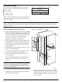
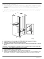
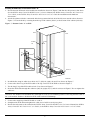
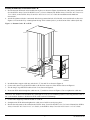
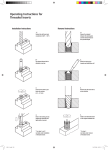
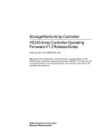
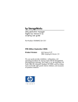
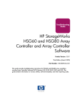
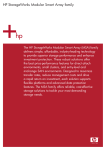
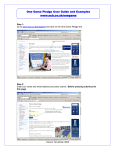
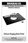
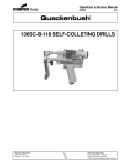
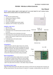
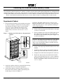
TM
Installing an External Cache Battery Cable
This document contains instructions to replace or install a second external cache battery (ECB) cable into a Departmental
or Data Center cabinet. In either case, these instructions assume that the cache module and ECB are already installed. See
the appropriate HSZ70 Array Controller HSOF Version 7.x Service Manual, the HSG80 Array Controller ACS Version 8.x User’s
Guide, or the HSZ80 Array Controller ACS Version 8.x User’s Guide for help on installing an ECB or cache module.
Departmental Cabinet
1.
Ensure that the ECB and cache module are in place
as shown in Figure 1. Shut down the subsystem as
described in the HSZ70 Array Controller HSOF
Version 7.x Service Manual, the HSG80 Array
Controller ACS Version 8.x User’s Guide, or the
HSZ80 Array Controller ACS Version 8.x User’s
Guide.
Figure 1. Routing the ECB Cable in a Departmental
Cabinet
CAUTION: The ECB cable has a 12-V and a 5-V pin.
Improper handling when connecting or disconnecting
could cause these pins to contact ground, resulting in
cache module damage.
4.
Connect the long Y leg of the ECB cable to the right
connector on the ECB.
5.
If power supplies are used on the ECB-cable side of
the cabinet, route the single leg of the ECB cable
through the loops formed by the power supply cords
as shown in Figure 1.
ECB
CAUTION: The ECB must be disabled—the status light is
not lit or is not blinking—before connecting the ECB
cable to the cache module. Failure to disable the ECB
could result in ECB damage.
6.
Connect the single leg of the ECB cable to the cache
module.
7.
Install the cable ties and secure the ECB cable—tie
both Y legs of the ECB cable with the top cable tie.
8.
Straighten the ECB cable and tighten the cable ties.
9.
Restart the subsystem as described in the HSZ70
Array Controller HSOF Version 7.x Service Manual,
the HSG80 Array Controller ACS Version 8.x User’s
Guide, or the HSZ80 Array Controller ACS Version
8.x User’s Guide.
Splitter
6
3
5
2
4
1
6
3
5
2
4
1
Cable tie
and mount
Cache
modules
CXO5894A
2.
Attach the splitter, with the countersink hole facing
outward, in its recess as shown in Figure 1.
3.
Attach three adhesive-backed cable tie mounts to
the inside of the cabinet, equally spaced along the
inside edge, as shown in Figure 1.
© Digital Equipment Corporation 1998. All rights reserved.
EK–HSZ70–TE. C01
Data Center Cabinet
The Data Center cabinet may require up to four ECB
cables, one for each of the following cache modules:
n
n
n
n
Figure 2. Cache Modules “A” and “B”
Controller A
Top cache A
Controller B
Top cache B
Cache A
Bottom cache A
Cache B
Bottom cache B
CXO5608A
Figure 2 shows the relative location of cache modules A
and B in each SW370 rack-mountable enclosure in the
data center cabinet.
NOTE: All directions are relative to your view of the cabinet. For example, left, front refers to the left side of the
cabinet when you are in front of the cabinet. Likewise, left, rear refers to the left side of the cabinet when you are
behind the cabinet.
Figure 3. Top Cache “A” to ECB
Installing the ECB Cable for the Top Cache “A”
1.
2.
Ensure that the ECB and cache module are installed
as shown in Figure 3 and that the subsystem is shut
down. See the HSZ70 Array Controller HSOF Version
7.x Service Manual, the HSZ80 Array Controller ACS
Version 8.x User’s Guide, or the HSZ80 Array
Controller ACS Version 8.x User’s Guide for
installation and shutdown instructions.
Rear
Attach the splitter with the countersink hole facing
outward at hole 40 of the right, rear outside rail as
shown in Figure 3. Locate hole 40 by counting from
the top of the cabinet (hole 1) to the bottom of the
cabinet (hole 62).
3.
Install the four snap-in cable ties at holes 31, 33, 48,
and 52 as shown in Figure 3.
4.
Connect the short Y leg of the ECB cable to the top
connector of the ECB as shown in Figure 3.
5.
Tie the long Y leg of the ECB cable at hole 52 as
shown in Figure 3.
6.
Route the ECB cable through the cable ties 48, 33,
and 31 as shown in Figure 3. Do not tighten the
cable ties.
Front
40 40
Cache
A "A"
Cache
3131
38 38
3333
Splitter
Splitter
ECB
ECB
4848
5252
CAUTION: The ECB must be disabled—the status light is
not lit or is not blinking—before connecting the ECB
cable to the cache module. Failure to disable the ECB
could result in ECB damage.
Outside
Outside
railrail
Inside
Inside
railrail
CXO6025A
CXO6025A
7.
Connect the single leg of the ECB cable to cache A.
8.
Straighten the ECB cable and tighten the cable ties
to hold it securely into place.
9.
2
Restart the subsystem as described in the HSZ70
Array Controller HSOF Version 7.x Service Manual,
the HSZ80 Array Controller ACS Version 8.x User’s
Guide, or the HSZ80 Array Controller ACS Version
8.x User’s Guide.
Installing the ECB Cable for the Top Cache “B”
1.
Ensure that the ECB and cache module are installed as shown in Figure 4 and that the subsystem is shut down.
See the HSZ70 Array Controller HSOF Version 7.x Service Manual, the HSZ80 Array Controller ACS Version 8.x
User’s Guide, or the HSZ80 Array Controller ACS Version 8.x User’s Guide for installation and shutdown
instructions.
2.
Attach the splitter with the countersink hole facing outward at hole 47 of the right, rear outside rail as shown in
Figure 4. Locate hole 47 by counting from the top of the cabinet (hole 1) to the bottom of the cabinet (hole 62).
Figure 4. Top Cache “B” to ECB
Rear
Front
15
Cache B
31
33
38
40
ECB
45
48
Splitter
48
52
47
48
62
Inside
rail
Outside
rail
CXO6027A
3.
Install the five snap-in cable ties at holes 31, 33, (right) 48, (left) 48, and 52 as shown in Figure 4.
4.
Connect the short Y leg of the ECB cable to the bottom connector of the ECB as shown in Figure 4.
5.
Tie the long Y leg of the ECB cable at hole 52 as shown in Figure 4.
6.
Route the ECB cable through the cable ties (right) 48, (left) 48, 33, and 31 as shown in Figure 4. Do not tighten the
cable ties.
CAUTION: The ECB must be disabled—the status light is not lit or is not blinking—before connecting the ECB cable to
the cache module. Failure to disable the ECB could result in ECB damage.
7.
Connect the single leg of the ECB cable to cache B.
8.
Straighten the ECB cable and tighten the cable ties to hold it securely into place.
9.
Restart the subsystem as described in the HSZ70 Array Controller HSOF Version 7.x Service Manual, the HSZ80
Array Controller ACS Version 8.x User’s Guide, or the HSZ80 Array Controller ACS Version 8.x User’s Guide.
3
EK–HSZ70–TE. C01
Installing the ECB Cable for the Bottom Cache “A”
1.
Ensure that the ECB and cache module are installed as shown in Figure 5 and that the subsystem is shut down.
See the HSZ70 Array Controller HSOF Version 7.x Service Manual, the HSZ80 Array Controller ACS Version 8.x
User’s Guide, or the HSZ80 Array Controller ACS Version 8.x User’s Guide for installation and shutdown
instructions.
2.
Attach the splitter with the countersink hole facing outward at hole 40 of the left, rear outside rail as shown in
Figure 5. Locate hole 40 by counting from the top of the cabinet (hole 1) to the bottom of the cabinet (hole 62).
Figure 5. Bottom Cache “A” to ECB
Rear
Front
Inside
rail
Outside
rail
40
Splitter
ECB
45
52
48
Cache A
48
61
55
CXO6024A
3.
Install the five snap-in cable ties at holes 61, 55, (left) 48, (right) 48, and 52 as shown in Figure 5.
4.
Connect the short Y leg of the ECB cable to the top connector of the ECB as shown in Figure 5.
5.
Tie the long Y leg of the ECB cable at hole 52 as shown in Figure 5.
6.
Route the ECB cable through the cable ties (left) 48, (right) 48, 55, and 61 as shown in Figure 5. Do not tighten the
cable ties.
CAUTION: The ECB must be disabled—the status light is not lit or is not blinking—before connecting the ECB cable to
the cache module. Failure to disable the ECB could result in ECB damage.
7.
Connect the single leg of the ECB cable to cache A.
8.
Straighten the ECB cable and tighten the cable ties to hold it securely into place.
9.
Restart the subsystem as described in the HSZ70 Array Controller HSOF Version 7.x Service Manual, the HSZ80
Array Controller ACS Version 8.x User’s Guide, or the HSZ80 Array Controller ACS Version 8.x User’s Guide.
4
Installing the ECB Cable for the Bottom Cache “B”
1.
Ensure that the ECB and cache module are in place as shown in Figure 6 and that the subsystem is shut down.
See the HSZ70 Array Controller HSOF Version 7.x Service Manual, the HSZ80 Array Controller ACS Version 8.x
User’s Guide, or the HSZ80 Array Controller ACS Version 8.x User’s Guide for installation and shutdown
instructions.
2.
Attach the splitter with the countersink hole facing outward at hole 47 of the left, rear outside rail as shown in
Figure 6. Locate hole 47 by counting from the top of the cabinet (hole 1) to the bottom of the cabinet (hole 62).
Figure 6. Bottom Cache “B” to ECB
Rear
Front
ECB
48
Splitter
Cache B
61
52
55
47
Inside
rail
Outside
rail
CXO6026A
3.
Install the four snap-in cable ties at holes 61, 55, 48, and 52 as shown in Figure 6.
4.
Connect the short Y leg of the ECB cable to the bottom connector of the ECB as shown in Figure 6.
5.
Tie the long Y leg of the ECB cable at hole 52 as shown in Figure 6.
6.
Route the ECB cable through the cable ties 48, 55, and 61 as shown in Figure 6. Do not tighten the cable ties.
CAUTION: The ECB must be disabled—the status light is not lit or is not blinking—before connecting the ECB cable to
the cache module. Failure to disable the ECB could result in ECB damage.
7.
Connect the single leg of the ECB cable to cache B.
8.
Straighten the ECB cable and tighten the cable ties to hold it securely into place.
9.
Restart the subsystem as described in the HSZ70 Array Controller HSOF Version 7.x Service Manual, the HSZ80
Array Controller ACS Version 8.x User’s Guide, or the HSZ80 Array Controller ACS Version 8.x User’s Guide.
5
EK–HSZ70–TE. C01