1
NABU Commercial Terminals Ltd.
NABU 3100 Service Manual
PRELIMINARY
August 3, 1983
,
.
l'
i,
•
-----Application Keypad Mode (Figure 3-6)
ArranJernent
Audible Feedback
Block Editing Modes
Block (BLK) Mode
Character Attributes
Character Attributes (Figure 3-15)
Character Presentation On Screen
Audible Feedback
,
Character Set Selection
Character Attributes
Character Width Functions
Screen Background
Character Set Selection
Character \Vidth Functions
Comnlunication Commands
Communication Commands (Figure 4-1)
Communications Mode (Figure 3-9)
Communication Modes
Operation Modes
Conversational Control Functions
Transmission Control Codes
Interrogation Codes
Full Duplex (FDX) Mode
Half Duplex (BDX) l\.Iode
Local (LOC) Mode
Block (BLK) Mode
Communication Commands
Cursor Control (Figure 3-16)
Cursor Control
Page Records
Cursor Position Indicator
Cursor Position Reporting
Cursor Position Indicator
,
Cursor Position Reporting
,
Deletion Keys and Sequences (Figure 3-19)
Description of Key Functions (Figure 3-3)
Dip-Switch Settings (Figure 3-2)
Dip-Switches
Dual-Function Keypad
Edit and Insert Mode (Figure 3-8)
Editing Keys (Figure 3-1S)
Editing iVlodes
Block Fditing :\lodes
_
ESCap~ Codes which Define GO and G I Uigucc.; 3·[-1-)
Full Duplex (FOX) l'vlodc
Functional D~scrjption
GENERAL INFORMATiON
GLOSSARY OF TERMS
Graphics Mode (Figure 3-10)
.
Half Duplex (HDX) \loJ~
"
J~6:
~~lJt'_'<;1
i
O.l.02,82IRO/Q1OOO/D l.:W
INO'EX
_
_ _
.
.
..
.
.
..
.
.
.
.
.
.
.
.
.
.
.
.
.
..
.
.
.
.
.
..
..
.
..
.
_
..
.
.
..
..
.
.
.
..
.
.
.
..
.
.
..
..
..
..
.
3-8
3-1
3-17
3-22
4-4
3-17
3-18
3-17
3-17
3-17
3-17
3-17
3-17
3-17
3-17
4-4
4-5
3-12
4-1
4-1
4-1
4·1
4-2
4-2
4-3
4-3
4-4
4-4
3-19
3-17
3-21
3-21
3-21
3-21
3-21
3-24
3-5
3-3
3-1
1-4
3-11
3-22
3-22
3-22
3-18
4-2
1-1
1-1
5-1
3-13
4-3
I
II
!
I
II
t
HO\V TO BEGIN
How to Usc the Manual...........................................................................
Initial IIl~pect ion
·.···
Installation......
Interrogation Codes............
Introduction
Key Functions
Keyboard Layout (Figure I-I)
Local (LOC) J1vfode
Main Keyboard
Monitor Mode (Figure 3-11)
NABU3100 Specifications, Interface Cables and Options (Table 1-1)
Operating Procedures
,.....................
Start-Up
Status Line Access.....
Operating Switches and Control (Figure 3.1)
Operating Switches and Control..................................................................
Power On-Off Switch...........
Dip-Switches.......................................................................................
Operation Modes
Optional Features
Page and Cursor Position Indicator (Figure 3-17)
Page Records
Power On-Off Switch
PROGRAMMER NOTES
Protected Field Mode (Figure 3-7)
Purpose of Terminal...........
Rear Pane[, Video Terminal, Input Output Connections (Figure 2-1)
Receive (RX) and Transmit (TX) Speeds (Figure 3-12)
RS232C Paraoleters
RS232C Pin Assignments for Host Port (Table 2-1)
Scope and Arrangement
,.................................
Screen Alignment Display..........................................................................
Screen Background
Scrolling Region (Split Screen)
Set-Up Mode (Figure 3-5)
Set· Up Parameters, (Table 3-])
Standard Features
Start-Up..............................
Status Line Access
,..........................
Status Line Display..................................................................................
Status Line Set-Up J1v1ode
Status Line Format (Figure 3-4)
Status Line Set-Up Mode
Status Reset (Figure 3-13)
Tab Function Escape Codes...........................................
Tab Functions........................................................................................
Tab Function Escape Codes...
TefIninal Components
,.......
rvlain Keyboard
".
Dual-Function Keypad
,
:............
Video Display Screen.............................................................................
Transmission Control Codes
Transmission Delimiter Programming (Figure 4-2)
USER NOTES..................
User String (US) Keys
Video Display Screen
,
'...........................
2~j
I-I
2-1
2-1
4-2
I-I
3-1
l-5
4-3
1-4
3-15
1-2
3-4
3-4
3-4
3-2
3-1
3-1
3-1
4-1
1-4
3~21
3-21
3-1
4-1
3-10
1~1
2-2
3-16
4-1
2-1
1-1
3·26
3-17
3-25
3-7
3-7
1-1
3-4
3-4
3-4
3-7
3-6
3-7
3-16
3-25
3-25
3-25
1-4
1-4
1-4
1-4
4·1
4-6
3-1
3-25
1-4
NABU 3100 Service Manual
PrefaC3
d
PREPACE
.
{,.,r tf
I/~
,
~~,U
•i ~
The NABU 3100 Service Manual was developed as a complete instruction
manual for thevNABU 3100 Video Display Terminal.
Although the
technical description and operation is detailed, it is assumed that
only trained and qualified service technicians will attempt to
disassemble or repair the units. NABU Manufacturing Corporation has
prepared a course of instruction to inform suitable service
technicians on repair techniques for the NABU 3100 Video Display
Terminal.
The NAEU 3100 Video Display Terminal (NAW 3100) is constructed to
strict safety standards, but' very high voltages are generated within
the display unit, which could be a hazard to life; therefore, great
care shoUld be exercised when removing the covers of the NABU 3100.
Covers should only be removed when the·supply cord is disconnected.'
The NABU 3100 Service Manual is organized in a logical fashion, using
the following format:
Chapter 1
Introduction - A general introduction .to the manual, its scope and
purpose.
The physical and functional characteristics are also
included in this chapter.
Chapter 2
Description and operation - A technical description and operation of
the NABU 3100, in a modular manner. Each module is described in its
relative position of importance within the terminal.
Chapter 3
Testing And Troubleshooting - A logical approach to defining and
identifYing a fault or malfunction within the NABU 3100.
iii
NABU
~
.A
~~
ill
~.-
Pref'ace
NABU 3100 Service Manual
},
..,..
.
•.
'. .''{-,
~t
r.'l
1.2.
i
Chapter 4
J,
-
And Repair - The correct methods of disassembling and
assembling the modules of the NABU 3100.
Di3as~embly
,.",.),
~C:::>i
c--~
,~
'
"~' 'J'
..•..
~
Chapter 5
Alignment3 - The alignment procedures, presented in a logical
sequence, that must be carried out a~ter replacement of defective
modUles or components.
l","""-.''*''",'
~
Chapter 6
Illustrated P.art3 List - The identifioation and location of components
and modUles that field service personnel are authoriZed to replace.
Appendices
Ie
1v
NABU
.....
NABU 3100 Service Manual
Content
TABLE OF C01HENTS
CHAPTER ONE
INTRODUCTION
1• 1
1.2
1.3
INTRODUCTION
PHYSICAL CHARACTERISTICS
INTERFACE CHARACTERISTICS
CHAPTER TWO
CIRCUIT DESCRIPTION
.2.1
2.2
INTRODUCTION
CONTROLLER
Address Bus
Data Bus
Control Pulse Bus
Chip Select Bus
CRT CONTROLLER
Screen Data Bus
Scan Counting
Character Counting
Blanking and Drive
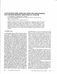
DESCRIPTION OF LOGIC SCHEMATIC DIAGRAMS
Schematic, 3100 Logic, 'Sheet 1
Schematic, 3100 Logic, Sheet 2
Schematic, 3100 Logic, Sheet 3
Schematic, 3100 Logic, Sheet 4
Schematic, 3100 Logic, Sheet 5
Schematic, 3100 Logic, Sheet 6
Schematic, 3100 Logic, Sheet 7
Schematic, 3100 Logic, Sheet 8
Schematic, 3100 Logic, Sheet 9
KEYEOARD
Keyboard ~licroproces30r
Key Matrix Scanning
Keyboard Output
2.2.1
2.2.2
2.2.3
2.2.4
2.3
2.3.1
2.3.2
2.3 ..3
2.3.4
2.4
2.4.1
2.4.2
2.4.3
2.4.4
2.4.4
2.11.5
2.4.6
2.4.7
2.4.8
2.5
2.5 .. 1
2.5.2
2.5.3
CHAPTER THREE
3.2.1
3.2.2
3.2.3
3.2.4
3.2.5
1 - 1
1
4
-1 - 6
2 - 1
.2
2
2 - 3
.2
5
2
6
.2 - 14
2 - 15
2 - 15
.2 - 16
2 - 17
2
17
'2 - 18
2 - 18
2
2
2
2
2
2
-
18
19
19
19
20
20
.2 - 20
2 - 20
2 - 21
2 -.21
.2 - 21
2 - 21
TROUBLESHOOTING AND REPAIR
GENERAL
TROUBLESHOOTING PROCEDURES
Initial Check, Group A
Power Supply, Group B
Primary Check of Monitor, Group C
Keyhoard t Group D
Controller Logic
DETAILED TROUBLESHOOTING OF MONITOR
Te - 1
3
3
3
3
3
3
3
3
-
1
2
2
5
7
9
- 10
- 11
NABU
"··11.. '
I
'-j'-. •
:fJ
NABU 3100 Service Manual
Content
:~
'"
J
.1
J
_I
i
:1
i'
~I
l'
CHAPTER FOUR
4.1
DISASSEMBLE AND REPAIR
DISASSEMBLY
4.1.1
4.1.2
4 - 2
4 - 2
Keyboard
__ ~_- 2
11 - 3
Display
REPAIR
4.. 2.1
General
lJ.2.2
Keyboard
4.2.3
Display Unit
4 - 3
4 - 4
4 - 4
CHAPTER FI VB
ALIGNMENTS
5.1
5.2
5·3
GENERAL
KEYBOARD
DISPLAY UNIT
Brightness Control
Display - Vertical Adjustments
Display - Horizontal Adjustments
Deflection Yoke Assembly Adjustments
5.3.1
5.3.2
5.3.3
5.3.4
:.1
5 - 2
5 - 3
5 - 4
5 - 4
5
4
5 - 4
5 - 6
~c,
CHAPTER SIX
SERVICE PARTS"LIST
6.1
INTRODUCTION
6 - 1
6.2
KEYOOARD
6.3
CONTROLLER
6.4
6 - 2
6 - 3
MONITOR
6 - 5
APPENDIX
A.1
A.2
A.3
A.4
A.5
A.6
A.6
NABU
Controller Component Layout
Schematic, 3100 Logic
Monitor, Component Layout
Schematic, Monitor, 12" SAMSUNG
Schematic, Video Monitor 4
Schematic, 3100 Power Supplies
. Schematic, Serial Keyboard
'Ie -
2
A- 1
A - 3
A - 21
A - 23
A - 25
A - 27
A - 29
Content
NABG 3100 Service Manual
.'
;e
I
~
I.
TABLE OF CONTElfI'S
:.J
FIGURES
1.1
2.1
2.2
2.3
2.4
2.5
2.6
NABU 3100 Video Display Terminal
1 Bus Interconnection Diagram
2 ~-2 .'~
Block Diagram of the Address Bus
2
Block Diagram of the Data Bus
Block Diagram of the Screen Data Bus
2 Block Diagram of the RD, MREQ and WR
2 Signals
. Block Diagram of the 10REQ, M1, and
2
BUSAK Signals
Block Diagram of the WAITRQ, BUSHQ, RESET,
2
INTRa, and NMI Signals
2
Format of Output Characters
Location of Adjustments on the Monitor
Board
5
Location of Deflection Yoke and Magnets
5
2
4
7
8
9
11
12
13
22
5
7
TABLES
1.1
1.2
3.1
3.2
3.3
3.4
3.5
6.1
6.2
6.3
6.4
Physical Characteristics of the NABU 3100
Characteristics or NABU 3100 Interfaces
Initial Check, Group A
Power Supply, Group B
Primary Check of Monitor, Group C
Keyboard, Group D
Troubleshooting Chart for the Monitor
Service Parts List For The Keyboard
Service Parts List For The Controller
Service Parts List For The SAMSUNG Monitor
Service Parts List For The MON-4 Monitor
1
4
1 - 6
3 3
3 5
3 - 7
3 - 9
3
11
6
2
6 - 3
6 - 5
6 - 6
I
TC - 3
NABU
CIIAPTE:R ONE
INTRODUCTIOR
NABU 3100 Service Manual
Chapter Content
CHAPTER ONE - INTRODUCTION
TA.Bl.E OF CONTIDf1'S
-
I
1.1
INTRODUCTION
1.. 2
PHYSICAL CHARACTERISTICS
1.3
INTERFACE CHARACTERISTICS
1 - 6
Figure 1.1
NABU 3100 Video Display Terminal
1 - 2
Table 1.1
Table 1.2
Physical Characteristics of the NABU 3100
Characteristics Of NABU 3100 Interfaces
1
1
1 - 1
.-1--- .q
~j
4
6
,
-.. --,-I
':;'.~
.~
NABU
Tel - 1
L
NABU 3100 Service Manual
1.1
Introduction
INTRODUCTION
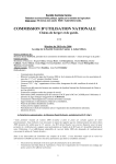
The NABU 3100 Video Display Terminal (NABU 3100), shown in Figure 1.1,
is a smart data terminal based on the logic of a Z-80 microprocessor.
The NABU 3100 is capable of communicating with a host computer, in
either a full-duplex or half-duplex mode, through an interface cable
operating under the RS-232C standard ru~e~6
The
standard
features
of
NABU
the
3100
are
as
follows:
Keyboard
Detached, with a coiled cable connection to the
terminal.
Full typewriter layout, with separate 14-key numeric
pad plus cursor control keys.
Display - 24 lines x 80 columns (one page) of characters.
Status line
25th
user-writeable.
line
(beneath the page),
user-selectable,
Display background - Grey, or optional purchase (green or amber).
Split screen - User-definable, split size.
Display memory - 1 page (second
pag~
optional purchase).
Scrolling - Keyboard-selectable, smooth or jump scroll.
Display characters - 7 x 9 dot matrix in a 9 x 10 dot field; may
be double width on a single line. Four different highlights on"a
oharacter are Possible: blink, bold, reverse, and with underscore.
Editing - Full editing fUnctions,
~th
protected
rields~
User strings - 16 user-programmable strings on 8 keys.
=- .
Escape sequences - ANSI X 3.64-compatible.
Transmission - Block transmission capability:
partial page.
1 - 1
line, page and/or
NABU
NABU 3100 service Manual
In~roduction
\
I
I
1
I
;I
j
i
!
Figure 1. 1
NABU
HAW 3100 Video D1.splay Terminal
1 - 2
Introduction
NABU 3100 Service Manual
Data transmission speeds - 15 baud rates from 50 up to 9,600.
Transmit and receive speeds are independantly selectable.
Power Requirements - nominal
depending on the model.
110
or
220
VAC,
60
or
50 HZ,
Optional features that may be purchased are:
r'"
Composite video output.
Backgro~nd: green or amber.
Display memory: second page.
National character sets.
Output: bi-directional, buffered serial-peripheral port •.
J
~e
.,
.
'f!
.11.:..1
II
_
~
;.:'
:•.. '
'1,
..
.•.
'~-'
•
~
•.•.....
...
, - 3
NABU
NABU 3100 Service Manual
Introduction
1.2
PHYSICAL CHARACl'EJUsncs
The NABU 3100 Video Display Terminal has the physical characteristics
shown in Table 1.1.
NAME
<
Available versions:
Standard
Receive Onl:,'
",
DiIne!\5io!\s
t
t]
~J
W
H
D
I
51.5 cm x 55.5 em x 3!l.O em.
42.0 em x 37.5 cm x 3!l.O CIllo
51.5 em x 22.5 Cm x 8.5 em.
Weight
7]!
16.5 kg.
13.3 kg.
3.2 kg.
Standard
..
Display
Keyboard
~
.
.
~,
External Connections
:]
Jl - AC power input.
J2 - Keyboard connector.
J3 - Optional serial data communications
interface.
J4 - Serial data communications
interface to modem or host
computer.
Display
~]
~]
~~.
With keyboard.
Without keyboard.
Standard (c/w keyboard)
Display Only
Keyboard
-,
~,
CHARACTERISTICS
-
~.]
Keyboard
J1 - Connector to
Configuration
NABIT 3100 115v, 50/60 Hz.
NABU 3100/EXP 230v, 50/60 Hz.
Power Consumption
NABU 3100
~,_l
NABU 3100/EXP
.]
Table 1.1
dis~laY.
150/130
VAC, 50/60 Hz.
210/260
VAC, 50/60 Hz.
Physical Characteristics
or
the HABU 3100
'"l
,
-,
L.
nABU
1 - 4
]
»
=
=-
-==
LZlt
i
Introduction
NABU 3100 Service Manual
,~
NAME
CHARACTERISTICS
-
.
Overload Protection
NABij 3100
Fused 1A Fast Blow.
--
NABU 3100/EXP
Table 1.1
--,-
Fused Dual O.6A Fast Blow.
Physical Characteristics .of' the HAW 3100 (Continued)
=
1 - 5
NABU
'
NABU 3100 Service Manual
rntroductic)n
DiTER'FACE CIlARAcnm:rsn:cs
The interface characteristics of the NABU 3100 are as shown in Table
1.2.
NAME
CHARACTERISTIC
Interface Cables
J2 terminal to keyboard
Conforms to Standard RS-232C (CCITT-V.24).
Current-Loop Adaptor Cable
Special, 20 mA consumption.
J3 to peripherals
Conforms to Standard RS-423.
J4 to host cornputer
Conforms to Standard RS-l123.
Communication from J4
-~---
Code
ASCII and ANSI x 3.64-compatible Escape
Sequences.
Type
Serial Asynchronous, switchable XON, XOFF
or DTR control from local or host
computer.
Speed
50 to 19200 baud, split send/receive.
Method
Sequential character in Conversational
mode, or by line, message, or page in
BUffered Transmit mode.
Mode
Full-D~plex,
Character length
7- or 8-bit, selectable.
Parity
Odd/Even/None, selectable.
Table 1.2
NABU
Half-Duplex or Echoplex.
Characteristics Of NABU 3100 Interraces
1 - 6
-;:
CllAPTER 'tWO
CIRCUIT DESCRIPTION
.'i
i~
!--
~
NABU 3100 Service Manual
'.
•-. . -.6
~
Chapter Content
CHAPTER 'nJO - CIRCUIT DESCRIPTION
~~
TABLE 01"
2.1
2.2
2.2.1
2.2.2
2.2.3
2.2.4
2.3.1
2.3.2
2.3.3
2.3.4
2.4
2.4.1
2.4.2
2.4.3
2.4.4
2.4.4
2.4.5
2.4.6
2.4.7
2.4.8
2.5
Figure
Figure
Figure
Figure
Figure
2.1
2.2
2.3
2.4
2.5
Figure 2.6
Figure 2.7
Figure 2.5
CONTIDlTS
INTRODUCTION
2 - 1
CONTROLLER
Address Bus
Data Bus
Control PUlse Bus
Chip Select Bus
2 - 2
2 - 3
2 - 5
2 - 6
2 - 14
CRT CONTROLLER
Screen Data Bus
Scan Counting
Character Counting
Blanking and Drive
2 - 15
DESCRIPTION OF LOGIC SCHEMATIC DIAGRAMS
Schematic, 3100 Logic, Sheet 1
Schematic, 3100 Logic, Sheet 2
Schematic, 3100 Logic, Sheet 3
Schematic, 3100 Logic, Sheet 4
Schematic," 3100 Logic, Sheet 5
Schematic, 3100 Logic, Sheet 6
Schematic, 3100 Logic, Sheet 7
Schematic, 3100 Logic, Sheet 8
Schematic, 3100 Logic, Sheet 9
2
18
2
18
2 - 18
2 - 19
2 - 15
2 - 16
2
17
2
17
2
2
2
2
- 19
- 19
- 20
- 20
2 - 20
2 - 20
KEYBOARD
2
Keyboard Microprocessor
Key Matrix Scanning
Keyboard Output
2 - 21
2 - 21
2 - 21
Bus Interconnection Diagram
Block Diagram of the Address Bus
Block Diagram of the Data Bus
Block Diagram of the Screen Data Bus
Block Diagram of the RD, MREQ and WR
Signals
Block Diagram of the 10REQ, M1, and
BUSAK Signals
Block Diagram of the WAITRQ, BUSRQ, RESET,
INTRO, and NMI Signals
Format of Output Characters
2 - 11
TC2 -
1
21
2 - 12
2 - 13
2 - 22
NABU
.1
Circuit Description
NABU 3100 Service Manual
2.1
:rnn:ODUCTION
The NABU 3100 is a -direct entry terminal able to transmit and recieve
data from a host computer, one character at a time, or send to a host
computer from the keyboard.
The keyboard translates an input from
the key matrix (key pressed) into a coded binary character compatible
with the ASCII code. This character is written into the memory of the
host computer together with any command bytes which may be necessary
for special attributes of the character. The host computer responds
by transmitting the characters back to the terminal.
The terminal
inspects the cOIllIlland bytes and directs the character to the screen
character memory, and directs the commands to the attribute memory to
determine the visual appearance of the character.
t.
The screen scan rate is 10 scan lines per character height, and ·to
ensure that only complete characters are displayed on the screen, the
scan lines are joined by a link list method or accessing memory. The
list contains the count .for the scan lines and resets on the 10th
line, preventing interrupts from stopping th~ character scan.
There are three memories built into the NABU 3100, one is a read
only memory where the operating program is permanently. stored, another
.for the attribute· information, and finally one for a scratch pad
memory where incoming data is stored.
'•.
:i
-
·1
~,
i~'
I
.I:
i
.
2
1
NABU
~
Circuit Description
NABU 31GD Service Manual
CONTROLLER
i
I""
1
I
The NABU 3100 users a Z-80 microprocessor and its associated program
memory to control the functions of the unit at a rate determined by a
crystal controlled oscillator operating at 14.7456 MHz.
The
controller contains all of the controlling circuits including the
microprocessor and is mounted on a single printed circuit board (PCB).
The circuits use integrated circuits to perform the following
functio1l3:
a.
Central Processing Unit (CPO) to control the fUnctions of the NAEU
3100. The CPU schedules information and determines the routing of
information.
b.
Timer to generate master timing signals to gate information
between the various blocks of the NABU 3100. The timer and the
CPU derive their timing cycle from the 14.7456 MHz crystal
oscillator. All timing functions are multiples of this frequency
and asynchronous signals from the NABU 3100 input ports are
translated to conform to this timing cycle •
c.
Program Memory contains the operating progr~ of the NABU 3100 it
is a read only memory and_is acces~ed by the CPU to perform the
functions required.
d.
Scratch pad Memory is a read-write memory used as a data storage
medium for data to and from the host computer.
e.
Character memory is a
character data.
f.
Attribute memory is a read-write memory used to store attribute
data.
The major attributes use in the 3100 are double width
characters and character highlighting.
g.
Screen character data drivers copies the output of the character
memory onto a line bUffer for transmission to the Cathode Ray Tube
(CRT). These drivers are actuated durir~ a CRT copy cycle.
h.
Universal Asynchoronous Receiver Transmitters (UARTts) match the
CPU transmission rate to the keyboard and the input ports
transmission rates. The UART's generate the correct signal timing
rates.
i.
The controller incorporates a set of option switches and their
associated drivers to select the options ava"ilable to the NABU
3100. The major options are, change of baud rate, data coding and
national character sets.
~
.
NABU
read-write memory used t.o· store screen
2 - 2
'1 I!
I"
I
Circuit Description
NABU 3100 service Manual
1
1
~
'\I
I
The controller interfaces with video circuits to produce and refresh
the characters on the CRT display. The video circuits are contained
on a separate PCB called the Monitor.
I
The controller uses buses to interconnect the runctional units of the
system, there are four major buses, the address bus, the data bus, the
control pulse bus, and the chip select bus •
.•"
f
l~
2.2.1
1.
f,
Addre:5s Eus
The address bus is a 16-bit address bus (AO to A15) connecting the
functional modules of the NABU 3100 illustrated in figure 2.1. When
the .CPU requires data it sends an address through the address bus to
identify the location of the data required by the operating program.
I
I
i
i
-,
.....,
.-."
'.
~'
~.
,"
2 - 3
NABU
Circuit Description
NABU 3100 Service Manual
t
~
~
~
'2
~
-e
=
....
...'\l
~
'"'
<t
'j\l
lhli
.
<:1.0
_ ..J
_0
"J:
I.J
Cl/
0
I
l
'"
":J
'4
II>'
i ii
':I
U1
--
•..
~
'"
ii
!
oJ
~
-z
'"
'lI
.3
~
00
o~~
~~
."
~
:J:t>l.
\J""~
<t 'U
~
t>.
¢
.....
~
01\
:s
~
.
\II
~
:s
~
:5
~
c..
~
III
i~
'2
8f=ij
<>
(/I
-.l.
\'!Ill~
~
U
~
-.
IO,J
C!l
A
..
JU
'"
l.uo
:s
j::r
..
oJ:!
-
•
::r
'"
~:
~~,J
VIJ
'U -
\'
~
't-~~
1:
~
0
~
oJ
l~
-,.~
..
at;
jl.
~
0
if
~
"Z 'tl
:::J
C
J
<:l.
v
0
\.l
~~~ to
-
!
"'"
• \0-
~~
r ~
•.:i ::::l::f
f r
I-(~
o..c
1I"I;:s
--
Figure 2.1
hoo
~
:c
Bus Interconnection Diagram
2-4
,
NABU 3100 Service Manual
Circuit Description
The address bus accesses the ,following modules
illustrated in a bl~ck diagram form in figure 2.2:
a.
which
are
also
Memory) memories
The EPROM ts form a 16K x 8 bit
read ortly memory located at positions 16D, l1D, 19d and 20D on the
controller PCB.
,The four EPROM (External Programmable Read Only
which form the Program Memory.
b.
The two memory modules forming the Scratch Pad Memory.
The memory
is a lK x 8bit read-write memory located at positions l1B and 16B
on the controller PCB~
c.
d.
The eight Random Access Memory (R.M1) module.s forming the Character
Memory. The memory is a 4K x 8 bit read-write memory located at
positions 12B, 13B, 14B, 15B, 17B, laB, 19B, and 20B on the
controller PCB.
The f'our RAM modules forming the Attribute Memory. The memory is
4K x 4 bit read-write memory located at positions 17B, 18B,
a
19A,and 20A on the controller PCB.
2.2.2
e.
The two decoders forming the memory. chip sele,at (CS) signal
decoders.
The decoders generate the select signals for the
appropriate melnory.
The decoders are located at 17F and 19F on
the controller PCB.
.,
r.
A Buffer module to increae the drive capability of' the screen
address lines AO-A3, and AS. The Buffer module is located at 16F
on the controller PCB.
g.
Three Driver modules to drive the screen address lines during the
period of time the CRT Controller is copying data from the screen
memory to the line buffer memory. The Driver modUles are located
at 12D, 13n, and 15D on the controller PCB.
Data l3u8
The data bus 1s connected to the input/output connections of' the
addressable memories described in 2.2 and illustrated in figure 2.1
Data is channelled through the data bus to form the characters
displayed on the CRT screen.
A link list method of access to data
ensures that a character scan is completed before accessing a new
character line.
A block diagram of the data bus is shown in f'igure
2.3 and 2 .. 4, the data bus is directly connected to the screen data
bus.
2 - 5
HAW
NABU 3100 Service Manual
Circuit Description
The data bus also has access to the following controlling circuits:
a.' Two driver modules used to copy the output of the screen character
memory into the .line buffer memory during a CRT copy cycle. The
driver modules are located at lOA and llA on the controller PCB.
b.
A Driver module used to copy the output of screen data memory into
the line buffer memory during a CRT copy cycle. The driver module
is located a 10B on the controller PCB.
c.
A dual UART module connecting the CPU to the line and to the
keyboard. The UART module is located at 7F on the controller PCB.
e.
A programmer timer module used to generate three UART clock pulses
and one software timing function to control the operation of the
various UARTt s in the controller. The programmer timer module is
located at 4G on the controller peBo
r. A driver
module to read the settings on the option switches.
driver module is located at 21H on the controller module.
The
Control Pu1.se Bus
The control pUlse (CP) bus is the highway used by the ~ontrol signals
generated by various functional circuits of the NABU 3100.
The
control signals have mnemonic names generally derived from a
description of the signal function
The major signals using the CP
bus are shown in rigures 2.5, 2.6, and 2,70
0
NABU
2 - 6
Circuit Description
NABU 3100 Service Manual
--e
-
"'... ......'"
....
"' .. ~~I·.
'"
~~
~"~
~~Il::
"'-I"
~,'"
\'" ~
~~ N
~~
~{. <;>
...
.
~~:t '"'"
:::
~
<:J
..:
""..-
i
~
i
". I
.',...-~f
"T~i.
A ~
"'oD
~. 'S.~_
~
t/'- t
VI ii)
.. "l<->
~
~~\~\"
t
_.~
N
-.;
n
~
....
•
Q)
'I~~
~l:: ~
·~·I
liJ
~
'"
--,
\' ~
,
t
"e.
~::::
U
~
~
r-
I
lU-
-
to
('J
~
--
~~
",t-
.....
~~
~i'
~N
lu
~
.~ ,
~ ~ ~ 'l3-
'S
--'"
~
t
- .
't
~~ ~l..
~
-
~
~ ~'4'a
~'"~
...
~r""":
....
~
..:
~~I!
f
~o ~ d)\ r
\II
~ ~
'"
I:';
-
I-< .J t-'
IS:!:
f
. ~~I~ll
"-
~
li
1;;~
or,' ....
iiElel~
~1l'J -I ~
'<I'
~t:::
\J .......
~lt--
~
t
f
~ 1t
o• A~
.
"'-
-
~
"" ......... IP'",
"-"
..-
.
'&.
~ "'>-
t
N
~,
~
'"....
~Nt'
'"
~
f"
SFI;I~
~
"\J 1,.t\...
'" ~, ....
";::
'
...~~ ~'o,
'0:
... ,
Jl:- 'Q'
In
~;:; :':1
\.0
~ il~l..:
~ ~ '\;,<~,
... Ie .............
'l;C1l
I, ..N
"-
~ ~ ~Iltl~
"'~""
~
~~::; ~
~ )... ~~
~::::
~~~
N ...
""''';:I,
~
.
~
t
t
~ to-~~_ ~...
N
-
't.
I
~'>:;;_G"l
'lI1
lJ
•
~~
f
0
.
~"''~
~
~ en
III
--
t
'{ 'l; - .
"t
:)
~
(ll
...
\i, ~~ , ~f,~~~:::
~
""
'"
!oJ
....
t
~I"~tn
~
IQ
~
:::
I'E(-
!-Nip
~l
t
~
Q
Q
IT'
;t~ll ~
~ I.... l'
t
_
J1_
I
'i:.., ~
,... ~ ~
.Jp'
~
\I
.....
\u' ~ I.t. ~
0
'k
~
I"
,
II'
....
~
.•":..-,.,
Figure 2.2
Block Diagram of the Address Bus
-
~
2 - 7
.,..,, -
NABU
.. -'1a
11
ililillll
'1111,~IlI~1
1111
i I~
~llil il
,ilihD~
1IIIIillllli
11M'
e
.~'
iilillilil.
n
....
'"S-
;;
o
~
~
I-.Jo
cT
t:I
CD
, C/'V
....
NO
t::
12t:
tz:I
~
(.0
Q
'1
1-'-
Eff(oM'f
2732
'1
ell
f\)
177)
w
:.,.¢
•
I"f"""
211'1
5CI{. RAM
, ell,
--;Z"ii"1
r-
---
'r-- 7'1LS'F-7
101'1,11"1
7-'1
74
t-- 1'111,
Ile,
CW. PR/Vci'
7·'/
,oj'l3
~
~
~
r-
77
~
1
, 'l7>Z
I-
tj
0)
SCIr,
~PR.oM f
CJ
::0;-
1
1-'-
g
CHAr?
'l>ArA
See
r;~ r;..t{ '2 f1-
....0
tJj
f\)
'0
cT
-;CJ:ccN
-
CH,MC""
tf~M
'Z1)1t
103
t--
>--
cT
P'
1r:J/j,l~";
~
MIVe-
'?"'S7."~- ~
1t'13
--=;:iT
5Cf(~EN
,14 rrlf'"
t'ATA
<:II"UM
27"!-"l
,10-
too
'2/1'1
/2.a,
l'S/)
7-4
7-~
(0
,fTr
3-r/
3-¢
~PR~M2.
0
'"1l
'2.11 1/
.
tj
z
PJ
fJ
EfROM')
2731:
~
10-
CJl
.
~
-
.
7'r,{
>--
:<>
CII. <'Ie",",
. 211 f(
~
w
-"
o
o
1713,/,s15
~
-
til
(l)
'Sr/:!.
fW~
I:xl''''"~ - 1 0 -
7-f/
LINcilMr
"j;j'j(f88"
7F
-:;:;-
.~
'--
-
MK38/J'1
.§L.
7-P
cpr.
'nntil(
'i'iKiSiiz
L.~6
7- "
'"S
~w.
<
l-'CJ
7'1L<;3(,7
'--
2IH
(l)
~
::;::
Pl
~
I-"
- ---~_.~~._-----
--------'
'i~ !11:lliiI~f
'~li!,I.I·'
'1Iilll!!li!ilil
111l!~!I!IIII!
"I'!I i~ I1IIIIII il~~UlliJ ~m! ~ililil,IIII!II.lil'.!I~~1 !l l t ,:I~lll! !i~lj!I.ll'
e
.'1
11 Ii
hs., l~i"if.mp'.II.llllillilllllll!!i!i ~Wlilil,1 II!I I! jliliiii!,._~!~~~,
Ill! iliilil•••
e
z
>
~
w
~
o
o
""1
t
tn
ij
I
f'
(D
I\)
•~
<D
CI/,N'ltI!JZ
AT.l)/{IVEil
/I r·rill '1£ (l.
71/[.$'3' 7 ~~'
CPtJ ---"" 7'1~H""
I-.~ /lA, luI
lot?>
p,t-r.t
7·d
7·~
..--
0
()
X'
'II
....~
<;'O1-¢
7</1.53'7
Q
I()""IIA
@
~
I.IN~
LUJ~I'1~~
ts:l
I-'
I>
2/1UI
~
~
~
1-'1
I'S' - /'l.
L/III!"
1r
1<1('>317
~
""t,;A
UnA
-7-'1
'SA
~
~p)
~
t:I
~
~
'i
fI,)
I
\0
I
~
0
.....
..--
.2.!l:.L
I(,A,I"SA
$,.4'" ern..
71lL SI(, /
J.lN~tt'J!t""
11777l. /lIt"'/
~
"'2Ii'lA
~
-:;;c.r- .
~
7-'1
~
-::;=tr
liNe' ,.,~,.,
t...-
2/1t<'1
~
"!-¢'
(1'
if
en
()
'i
(D
C!)
::s
1/""'11. tre;~
IITT((ti1~.H
2tJi1
>- 2J
A ,/'JA
>-
l~~
7'1I..SJ77
-u-s
~
.
.
I.A1T
~
seA'"
un
7'1£
a I!.
-j:¢
~
(1'
II)
~
C4
1/"""
IITTI(1"lffl
~
1.(11/
11//1, 131/
7-1-
1-00
. Cifill( tU 1/
(/1"('(1(
'1,ft.n,'
Iii3
------:\
/";·6
.
~
21/'
n
1-"
--:s:r
'1
7'~
.....
(1'
()
s::
t:l
ro
lO
()
ATT,( Me",
I--
!2:
>
~
!
!
11/'1
'"'$
I-''0
t8A117~
.....
-;;4
(1'
o
::l
Circuit Description
NABU 3100 Service Manual
The derivation and use of the signals are as follows:
RD (Read) signal is generated by the CPU to indicate that the CPU
a.
is in a ·read state, ready to read information from the host
computer, keyboard, serial/parallel input port or signals from the
timer.
RD logically AND gated with MREQ (memory request) will
produce MR (memory read) to tranfer the information is the-program
memory to the CPU.
MREQ (memory request) is generated by the CPU to indicate that the
CPU requires informtion from the program memory.
The address of
b.
the specific informat~on will also be on the address bus so that
when the memory read, signal is generated, the program memory will
transfer the information to the CPU.
..
c.
WR (write) is generated by the CPU to advise the memory that the
CPU is placing information on the data bus. This information will
be written into the random access memory (Rfu~) module which has
been addressed on the address bus.
d.
IOREQ ( I/O request) is generated by the CPU to indicate that the
CPU is performing an input/output operation from. the line UART,
the SPI UART, or the timer circuit.
e.
The M1 (memory cycle 1) signal, generated by the -CPU is used by
the 110 dervies to transfer information. The signal informs the
I/Odervices that their interrupt request has been accepted.
~.
The BUSAK (bus acknowledge) signal is generated by the CPU when it
has finished an operation and has released control of the address
and data buses. The address and data buses will then be available
to any other device. Normally a CRT write signal will be used as
a result of the EliSAK signal to start the first scan on the CRT
screen.
g.
The WAITRQ (wait request) signal is generated by the CPU, it is a
scheduling signal to suspend read or write operations between the
memories and the CPU.
Normally memory access times are fast
enough to ensure that WAITRQ cycles are not required.
Although
this signal is connected to the 11ne UART and the SPI UART
modUles, it is not used by them.
h.
The BUSRQ (bus request) signal generated by the CRT controller
when it wa~ts to start a CRT write cycle. The signal causes the
CPU to suspend operations after the completion of the current
instruction and thereby release control of the address and data
buses •
.:!.......
.~
!!
NABU
2 - 10
....
~'
NABU 3100 Service Manual
Circuit Description
~w
Il..
lot
I~
C!'
t!lI'l
N
It>. -
I-
,w
If'oI
~
I~
Q
In
I
I..., lQ,
I~ll!
0
I"
f"-t:
I;) a..
(n
~
rt:
""Po
I'" .
11;oc
lL-
II'~
I 5:of!'
'"
...
\:t
~~
....
I..,
.~
I::
-r::!
j'
'"...
1-
:;
.
,<:'
~
t'oo
I
~
~
11-
""
I~ LL
tur-
13
N
(1\
10
.
-'"
~0
'!11
.
};
....
to
~~
'"
-oJ
I~
....
r::
.... J
0
Q
....
I~
b
P"
rI\
-. '"
7
0
t1.!.' <-
N
...
)-- E
>.I
rJ
If'
III
I/'l
~
...
~. ~
'"
V'
..I
'"
Q
V'
..J
ll\
~
~ I~
Figure 2.5
Ie
J~
0
\1..:> U)
~CL
ru
V
N
Block Diagram
or
,
I~
the RD, MREQ and WR Signals
2 - 11
......
t"
(>01
NABU
NABU 3100 Service Manual
Circuit Description
. -rl
ll..~
-
--lU
<oJ
~
11..'"
-. iii
~
'"
t:i
CllU
-.J
A
~
It!
...
l~
I j: _
Ie>!
I!l
0
-
'"
I~
~
~
V
!
t-
It:!
on
"
N
/"'I
f"I
of'
f::l"
~
j..,
I!.
~')
oJ
't-
I""
~ LL
I", .....
I~
15
r
. :,
~'
I~
:) \L
IWtz
13
to
I.,
;
r
v
I!
I
I ~ 'I"~.
<>!
-J
(u
~,
rro
...... -i
1_ ..
'"
\.I
l"
J
'1"0
I ........
H
VI
-'
w
I
~
to-
V'
..J
,r'>
-
-l>
"
~&
J
"'"
o
t-
N
I'"
J.q;
u.
0
N
Figure 2.6
'3 0
O-Ilo
",t'J-
!g
tN
,n
I;:
I~
N
ij
Block Diagram of the 10REQ, Ml, and BUSAK Signals
·e
2 - 12
NABU
,
.......
Circuit Description
NABU 3100 Service Manual
11
/~I
•
11
I~
.
I~
1__
J
I~
l-
12
l~tl
Iv
:-I.
11
Figure 2.7
Block Diagram of the WAITRQ, BUSRQ, RESET, INTRO, and NMI Signals
2 - 13
,
"-'.
NABU
NABU 3100 Service Manual
Circuit Description
i.
The RESET signal resets the CPU, the UART's, the TIMER, and the
This signal is generated
from the reset switch and is an external signal.
CRT controller to their initial state.
j.
The INTRQ (interrupt request) signal is generated by the line
UART, the SPI UART or timer indicating that they require the CPU
to perform a specific instruction. The CPU completes its-current
instruction and jumps to read the data at the address given during
the interrupt cycle. There is a priority order between the three
sources as shown below:
Priority 1
Priority 2
Priority 3
k.
2.2.4
line UART
SPI' UART
TIMER
The NMI (non maskable interrupt) is a signal generated by the CRT
controller to signifY the beginning of the CRT vertical retrace
interval.
Chip Select Bus
The chip select bus (CS huslia part of' the addressing function for
the memory address.
Logical combinations of address, bits generate
chip select signals to acce~JS particular memory addresses.
This
method of addressing reduces the number of connecting lines and the
number of driver modules.
--
It
....
~
;I
£e
-~:I§
..
"-
~
NABU
t---------------_..
2 - 14
NABU 3100 Service Manual
2.3
Circuit Description
CRT CONTROLLER
The CRT controller schedules the information for display on the CRT
screen.
It breaks each character line into 10 ::lcan lines, it also
controls refresh timing to ensure that the characters stay visible on
the CRT screen for the period of time required by the operator.
The CRT controller initiates an information write cycle by generating
the signal CRTWRT (CRT write). This signal enables the CRT controller
to access the CRT address and data drivers, and to place the address
bus under the control of the CRT controller. The contents of the data
bus is then available for transfer into' the line buffer' memory.CRTWRT also tranafers the contents of the character and attribute
memories into the line buffer memory forming a 12 bit wide data path
containing the character, its position on the CRT screen, and its
attribute.
2.3.1
~· '·-.· -.· I·. ·
~;;;;;'
~~:~~
~.
Screen Data Bu.s
The inforamation conveyed on the screen data bus has to take into
account a number of conditions. The first condition is that there are
10 scan lines to each character ~ine, and that the complete line is
scanned. The next condition is that attributes must be applied at the
time the character or characters are built up on the screen.
The
third condition is that a blanking pulse must be generated at the end
of each scan line to prevent the flyback trace from being visible on
the CRT screen.
During the first scan of each character row the following events occur
to achieve the above conditionS:
-
a.
The CRT controller activates the bus request signal to suspend
operation of the CPU and to release the CPU from the address and
data buses.
b.
The CRT controller takes control of the address lines using the
screen address drivers (location 12D, 13D, AND 15D on the
controller PCB) to place the memory addresses generated by the
controller, onto the screen data bus.
c.
The screen character and attribute memory modules are addressed as
a 4K by 12 bit wide memory whose output is copied (using the
drivers located at lOA - .12A on the controller PCB)· to the line
bUffer memory (located at 4A - 6A on the controller PCB).
~(
I
~]I
2 - 15
NABU
Circuit Description
NABU 3100 Service Manual
d.
Simultaneously to event c, the screen character data is copied
into· the character generator module (located at 5D on the
controller PCB) to display the characters as they are copied;
attribute nata is copied to the attribute latch (located at 4B on
the controller PCB) sending attribute information to the video
circuits.
e.
The first two data bytes read out of screen memory contain the
information needed to operate the CRT controller; the next 80
bytes are character information. The CRT controller information
required is:
single or double-width characters
vertical drive
vertical blanking
first scan count
last scan count
line number
Scan Counting
The SCt'een scan rate is a function of. time and to obtain a complete
character line complete with any attributes, the CRT ~ontroller must
be able to access screen memory exclusively. The CRT controller uses
a DMA (direct memory access) operation to copy the memory contents
into the four bit register, for the addressas of data for transfer to
the drive circuits of the CRT.
j
,.
There are two four bit registers (U8B on the controller PCB) loaded
from the screen memory, the Last Scan No. Register, and the line
Attribute Latch.
The Last Scan No. Register contains the number of
the last horizontal scan in the current character row. The contents
of this register is fed to the Scan Count Comparator (USA on the
controller PCB) where it is compared for equality to the contents of
the current Scan Counter (UgA on the controller PCB).
The Scan
Counter is loaded during the start of a DMA operation with the number
or the first horizontal scan of the current character row.
This
counter is incremented as each horizontal scan of the character row is
diSPlayed. When the contents of the counter equals the output of the
Last Scan No. Register, the Scan Count Comparator sends a signal to
the First Scan Latch to indicate that the current character row is
complete and the CRT controller then finishes the DMA copy operation
allowing access to the screen memory.
;i,:-
The operation waits on an instruction to commence the DMA cycle for
the next character row.
I
--
I
1-'.~
'-.i.•.
.,f;i
,"tl
iF,
NABU
2 - 16
NABU 3100 Service Manual
Circuit Description
The Line Attribute Latch contains the addresses of the attributes
affecting the entire character row.
~,
Character Counting
-
~]
f]
J
-~]
=.=--s;:
f)
~.:~l.
~~-
J
~uf
,I
~~
During each horizontal scan a character position counter is
incremented with the address of the character an .its attribute to
place each character in its correct format and position on the CRT
screen.
The Character Line No. Latch (U9B on the controller PCB) is an 8 - bit
register, which is also loaded during the CRT Controller DMA
operations, .contaiU3 the current character row number being displayed.
The character row number is used by the Address Compressor (UlOD on
the Controller PCB) to generate the screen memory addresses for which
the character row will be assembled for display on the CRT.
The most
significant two bits of the Character Line No. Latch determine which
pair of screen memory pages will be used for display_
The character row number is incremented by the Character Counter
the Character Counter Latch (UTB and U9d on th controller PCB)
forming a "state machine tI supplying a binary count for the
displayed characters, the horizontal blanking signal, and
link-list addresssing sequence.
and
by
80
the
..•.
~
·~.· · · 1~
..
-)
,
-~~\
"~-I
The timing of counters and registers loaded during the CRT controller
DMA operations are clocked at the edge of the horizontal blanking
signal..
The horizontal blanking signal is delayed through the Line
Attribute Timing Latch (U60 on the controller PCB) to cause clocking
to occur at the correct time.
BJ anking and fuoive
The Horizontal Drive Logic (U14F, U15F, and U21B on the controller
PCB), the Double Width Logic (U4F and U13F on the controller PCB), and
the Line Attribute timing Latch combine the vertical blankii!g, the
decoded character counter states, the double width, and the horizontal
blanking to provide monitor drive signals.
NABU
2 - 17
£&1
£ -
_.
Mit
M
Em
NABU 3100 Service Manual
Circuit Description
e
2.4
DESCRIPTION OF LOGIC
scnoonc
DllGR1UI.S
!
i
This section is a short description of the function and identification
or logical circuits in the logic schematic diagrams shown in Appendix
A. This description will enable a technician to identify the function
of' a particular area on the schematic diagrams.
The description is
related to the sheet number in the title block of each sheet.
2.4.1
SChematic$ 3100 Logic, Sheet 1
This sheet contains the CPU, its associated logic and the screen
address drivers.
The f'ollowing major signals are generated on this
sheet:
a.
Bus Request (BUSRQ)
The BUSRQ signal is produced from the OR gate (15F) which allows
bus requests either from the CRT controller or from the expansion
connector.
b.
RESET
The RESET signal is generated automaticallY on power-up, or from
the expansion connector.
The time duration of the signal is
determined by the hysterisis feedback level restorer circuit
consisting of R21, C80, and inverters BG and 12F.
c.
Non-Maskabl,e Interrupt (NMI)
non-maskable interrupt signal, is generated by the CRT
controller during each vertical retrace time. For test purposes
this interrupt can be disabled by removing the ground connection
at 14F pin 12.
The
2.4.2
Schematic, 3100 Logic, Sheet 2
This sheet contains the memory chip selection generating circuits, the
EPROM memory, the scratch pad memory, and the screen chip selection
combining circuit.
The CRT controller reads character and attribute
data from memory as a 12 - bit word.
Screen character data is
addressed from 8000 to 8FFF (hexidecimal), and attribute data from
9000 to 9FFF (hexidecimal). The CRT controller can only address the
8000 series addresses and uses the combining circuit. to address the
attributes concurrently with screen characters.
I.
!
il '
iI.':1 :
i'f. '.
1.
I.
Ii
NABU
2 - 18
I:
I~
~t
II'
I
i
h
I
I
,
=
NABU 3100 Service Manual
Circuit Description
Schematic, 3100 Logic, Sheet 3
This sheet contains' the screen memory and memory data I/O circuits.
The 12 - bit data word for the CRT line buffer memory are derived from
drivers lOA, 11A,and 12A, during CRT write time.
i
2.4.4
Schematic" 3100 Logic, Sheet; It
This sheet contains the counter timer, the clock pulse oscillator, the
clock pUlse divider, the bell control, and the keyboard and bell clock
pulses.
a.
.:iii-
b.
The counter timer (4G) generates the three UART clocks and a
It consists of
four
programmable interrupt time delay.
independant timers programmed form the CPU. The three UART clock
timers use the system clock pUlse to provide clock outputs at pins
7, 8, 9. The software timer uses a longer frequency clock input
on pin 20 to generate longer time delays. The software timer can
interrupt the CPU using the INTRQ signal assuming the interrupt
priority enable (lEI) is a logical one.
The UAlfl' clocks run
continuously.
The clock pulse oscillator generates the master c!ock of 14.7456
MHz.
2.14.4
c.
The clock pulse divider generates the CPU system clock of 14.7456
MHz or 2.4576 MHz using modules 4F, 12F, 2F, and 2G.
d.
The bell control is controlled by the I/O commands 107 (bell on)
and I08 (bell Off), from modules 2G and 13F.
e.
Keyboard and bell clock pulses are generated by 1G an 1F using the
system clock pUlse as input. The keyboard clock is 30.72 KHz, the
bell clock is 1920 Hz, and the timer clock is g60 Hz.
SChematic, 3100 Logic, Sheet 5
This sheet contains the connections to the UART's the level
converters, the line output and the optional SPI port output lines.
2 - 19
NABU
NABU 3100 Service Manual
Circuit Description
_.4.5
Schematic, 3100 Logic, Sheet 6
This sheet contains all the set-up and option switch circuits.
Decoders 14H,16H, 1'9H and 20 Hare 3 - to - 8 decoder modUles to
select switch sections under the control of address lines AD and A1
using the enable signals CSSW1 or CSST;12.
Four switch sections are
read in parallel at anyone time and the result connected to the CPU
address bits 0 and 3.
2.4.6
Schematic, 3100 Logic, Sheet 7
This sheet contains the scan counting and part of the character
counting circuits.
2.4.7
Schematic, 3100 Logic, Sheet 8
This sheet contains the remainder of the character counting cirCUit,
and the blanking and drive circuits.
2.4.8
Schematic, 3100 Logic, Sheet 9
This sheet contains the video output circuits. The video is set to
one or four levels (off, dim, normal, bright) dependant on the value
of the attribute bits and the character selected.
The screen
background can be either black (off) or white (on).
The module IC retimes the two video .channels to eliminate spurious
timing dots caused by propagation delays through the attribute logic.
The ratio of the four video levels is set by the value of resistors
R7, Rl0, R11, and R12.
The amplitude is set by the values of
resistors R8 and R13.
Transistor Q2 is an emitter follower providing a variable-voltage DC
source to drive the video output ciruits. The contrast control on the
front panel determines the amplitude of the video output by setting
the DC voltage level at the base of Q2. Resistor R5 sets the maXimum
voltage available for the video output, and thus the maXimum contrast
available.
NABU
2 - 20
Circuit Description
NABU 3100 Service Manual
KEIIDARD
The keyboard contains the operator centrals of the NABU 3100 terminal.
The layout of the keys is in a standard QHERTY form with an e~tra set
of function keys as a top layer. A separate key pad is located to the
right of the keyboard. Some keys are multi-function a& rlsfined in the
NABU 3100 User3 Manual.
The keyboard contains a micro-processor to read the key pads,
the output coding, and perform control functions.
Keyboard
~croproces30r
forma~
'
The keyboard microprocessor contains an integral read only memory
( ROM) with a pre-determined program writ ten into the memory.
This
program interprets the key position and designates a code for it, this
code is output from the microprocessor as a number of bytes of data
(dependant on the character or function selected on the keyboard).
The program in the microprocessor cannot be altered by the operator.
The operations performed by the microprocessor are timed by an
external crystal oscillator running at 6MHZ~
Key Matrix scanning
The microprocessor outputs a binary count on its output ports P20
through P23 to the two decoder modules, and reads the input ports P11
through P17. When a key is operated, the binary count is altered and
the signal to the input port is a1tered.
The program in the
microprocessor identifies these changes and relates them to a code
representing the character code.
The microprocessor scans the
keyboard at a rate proportional to the oscillator and outputs the
character code as 300n as a change in the matrix is detected.
Keyboard OUtput
When a key is operated, a two or three byte transmission of data will
occur.
These bytes wil be status and data as shown in Figure 2.5.
Diodes are connected to the ends of the matrix to prevent phanton
output characters.
-
;I
2 - 21
NABU
J
Circuit Description
NABU 3100 Service Manual
'11.:
.•
;J
D
j
.~
Sta tus "
.~
11
-,
.
L..-_ _
t.
Page
·'.'rt.
lJ
.•~
"'-----pr i n t
Status 1
L.11
7
I
I
I
I
Data
I
I
I
l1-
Shift
Capslock
Repeat
Games Mode
Ready
.. ,
-'-1'·~
•.
Local
Fu11
'--1:
Not Used
Control
~
~D
~~J
__
'I
Figure 2.5
Format
or
OUtput Characters
NABU
2 - 22
J
_ _Logical
Xy
Posi tion
. or
"07FH It
11
I.,
i
CHAPTHR TIlREE
TROUBLESHOOTING AJ."'ID REPAIR
.
-
.-
Chapter Content
NABU 3100 service Manual
CHAPTER THREE - TROUBLESHOOTING MID REPAIR
j
a
TABLE OF CONTENTS
.
..
~
3.1
3.2
3.2.1
3.2.2
3.2.3
3.2.4
3.2.5
3.3
Table
Table
Table
Table
Table
3.1
3.2
3.3
3.4
3.5
GENERAL
3 - 1
TROUBLESHOOTING PROCEDURES
Initial Check, Group A
Power Supply, Group B
Primary Check of Monitor, Group C
Keyboard, Group D
ControlierLogic
3
3
3
3
3
3
DETAILED TROUBLESHOOTING OF MONITOR
3 - 11
Initial Check, Group A
Power Supply, Group B
Primary Check of Monitor, Group C
Keyboard, Group D
Troubleshooting Chart for the Monitor
3 - 3
-
2
2
5
7
9
10
3 - 5
3 - 7
3 - 9
3 - 11
I
I
,
J
TC3 - 1
NABU
,
,'j
Troubleshooting And Repair
NABU 3100 Service Manual
~e
'"
.~
GENERAL
This chapter establishes techniques for testing and troubleshooting
the NABU 3100.
It is important to define the problem area and to
apply a logical procedure to isolate the faulty component or
components •
•.1
....
.~
h·
:.1··
'I
.,
·:.·1··
3 - 1
J
NABU
Troubleshooting And Repair
NABU 3100 Service Manual
TROUBLESHOO'l'ING PROCEDURES
When troubleshooting tbe NABU 3100 it is an advantage to carry out a
set of procedures in a sequential method to recognize the problem and
to locate the faulty component. The procedure contains task outlines
each with an alphabetical prefix. Group A task outline is the_primary
sequence which will identify the problem area and direct the
technician to the next group task outline.
For any problem it is
advisable to start with Group A because it will also identify problem
areas for mUlti-fault situations, for this reason goup A is called
Initial Check.
3.2.1
Ini.tial. Check, Group A
The initial check of the NABU 3100 is listed'sequentially in Table
3.1.
•
NABU
3 - 2
I
III: I•
i
Troubleshooting And Repair
NABO 3100 service Manual
: ~!
~
l •
t
'!"
·'n I
:ii
,:,
I
n:' 1
STEP
SYMPTOM
ACTION
POSSIBLE FAULT
::1'
I':
I:
,;t..
A1
No operation
incorrect
installation
Dip switch setting
incorrect
-,,
A2
No short "beep n
(1 second) when
switching on.
Power supply
failure
Go to 3.2.2
A3
The "beep" is of
2 second
duration when
switching on.
Logic board fault
Go to 3.2.5
A4
No lights on
screen (scan
lines,
Characters,
nonesense data
etc.)
Fault in monitor
circuit
Go to 3.2.3
A5
A single
vertical or
horizontal line
on the screen
Fault in monitor
circuit
Go to 3.2.3
A6
Information on
the screen is
rolling
(vertically orhorizontally)
Fault in monitor
circuit
Go to 3.2.3
~
-e
Check security of
connector.
Check that power card
is connected to
correct power source.
Check that front
panel controls are
effective.
Adjust DIP switches
according to User
Manual.
Table 3.1
Initial Check, Group A
3 - 3
NABU
i i!
Ii:
II: I
H,
I,;
rj' i
I: !
i" l l
Troubleshooting And Repair
STEP
SYMPTOM
NABU 3100 Service Manual
POSSIBLE FAULT
ACTION
A7
Incorrect
display appears
when pressing
"SET UP" key on
keyboard
No response at all
(keyboard fault)
Incorrect
characters
(logic fault)
Go to 3.2.4
Go to 3.2.5
A8
With unit in
LOCAL mode, '
incorrect
characters on
screen
If occassionallY
missing characters
the keyboard is
faulty
A group of
characters missing
indicates a logic
fault
Go to 3.2.4
In REMOTE
mode, transmit
and receive
data is missing
or incorrect
Logic fault
Go to 3.2.5
A9*
Go to 3.2.5
* For this step a test configuration" must be used.
test must be configured as follows:
The terminal under
a.
The unit must be in REMOTE mode using SETUP mode or selected at
the DIP sWitches.
b.
A known good terminal must be connected to the unit under test
thrOUgh the main serial I/O port.
c.
Transmit data pin 2 shOUld connect to input pin 3 of good
terminal.. Receive data pin 3 should co:nnect to output pin 2 of
good terminal, and ground pin 7 should connect to ground pin 7 of
good terminal.
d.
The baud rates shOUld be the same on both terminals.
Table 3.1
~w
Initial Check, Group A (continued)
3-4
'I
!
Ii
NA~
Troubleshooting And Repair
3100 Service Manual
1
,I
II
1\
I
.
Power Supply, Group B
A DC voltmeter and an Ac voltmeter of sUitable range are used to
verify the operation of the power supply.
Instead of separate meters
a mUltimeter is acceptable as a test instrument. Table 4.2 lists the
steps in sequential order.
STEP
B1
TEST
The DC voltages
are checked at
J8 on the
Controller PCB
+12v (pin 1)
voltage check
POSSIBLE FAULT
ACTION
If +12 v is not
within 5l' of
nominal, VR2 and
associated circuit
components are
faulty.
Change VR 2,· and or
the associated diodes
and Capacitors
+5V (pin 2,
nominal V is
5.15) Voltage
check
If the voltage is
not within 5% of
5.15V, the +5V
voltage regulator
is faulty
Adjust R25 or change
VR3*
~,
+5V (pin 4)
voltage check
If the +5V is not
within 5% of
5.00V the +5V
voltage regulator
is faulty
Adjust R24 or change
VR1*
-12V (pin 5)
voltage check
If the -12V is not
within 5%, the
reference Voltage
regUlator is
faulty
Change VB 1 on
Controller PCB
Table 3.2
Power SUpply, Group B
I,
'.tt
3 - 5
....,
.
NABU
NABU 3100 Service Manual
Troubleshooting And Repair
STEP
TEST
ACTION
POSSIBLE FAULT
II
1\I'
B2
B3
*
The AC voltages
are checked at
J11 on the
controller PCB.
8V (Pins 1 & 2)
voltage check
i
I
I'..· ',.
If 8V is not
within 25% of
,nominal, the
transform8r T1 15
faulty
Change the
13V (pins 3 & 4)
voltage check
If 13V is not
within 25% or
nominal, the
transformer T1 is
faulty
Change the
All voltages 50%
or more out of
tolerance
Primary wiring
inc.orrect
Check wiring and
No voltage3 at
any of the
secondary
winding3 of
transformer T1
Fuses faulty, line
filter open
circuit, power
switch or primary
wiring faulty
Using the schematic
diagraJM verifY that
the items of the
power input, function
correctly.
Replace where
necessary.
transformer, T1
transformer, T1
source voltage.
RectifY where
necessary
On regUlator heatsink assembly bolted to chassis.
Table 3.2
Power SUpply, Group B (contiDued)
3-6
~oo
...,,
.
I
I
NABU 3100 Service Manual
Primary
Check ot Monitor,
Troubleshooting And Repair
G1"OUP
C
There are a number of. simple checks that can be carried out to verify
the condition of the Monitor circuit. The checks consider the SAMSUNG
Monitor only. The information for the MON-4 Monitor is contained in
Appendix B. If the Monitor is found faulty, it may be fur~her tested
by using the information in 3.3. The primary check of the monitor is
listed sequentially in Table 3.3.
~,
Table 3.3
Pr:imary Check of Monitor, Group C
3 - 7
NABU
Troubleshooting And Repair
C3
Table
POSSIBLE FAULT
TEST
STEP
NABU 3100 Service Hanual
ACTION
After adjusting
the brightness
control to
obtain a
rectangle of
scan lines,
verif'y that
there is data or
a cursor line
If there is
nothing on the
screen the Video
circuit in the
monitor is faUlty
Refer to 3.3 to
troubleshoot the
monitor
Horizontal line
only on display
Vertical circuit
in monitor faulty
Refer to 3.3 to
troubleshoot the
monitor
Vertical line
only on display
Horizontal
circuit in monitor
faulty
Refer to 3.3 to
troubleshoot the
monitor.
3.3
PriJDary Check
om
of Monitor,
3-8
~.
Group C (continued)
I
I
NABU 3100 Service Manual
3.2.4
Troubleshooting And Repair
Keyboard, Group D
The keyboard is tested when connected to the terminal.
All supply
voltag0~ for the keyboard are derived from the terminal display unit.
The keyboard Checks are listed sequentially in table 3.4.
STEP
D1
SYMPTOM
Malfunction of
the keyboard,
identif'ied from
Initial Check,
Group A.
D2
Table 3.4
POSSIBLE FAULT
ACTION
No output from the
keyboard.
Connect oscilloscope
or logic probe to J3
pin 2 on controller
logic PCB. VerifY
that there are pulses
on this pin when
various keys are
operated on the
keyboard. If there
are no pulses on the
pin go to step D5.
Incorrect voltage
levels in the
keyboard
Measure ~he keyboard
power at Z1 between
pins 16 and 8 (put
positive lead 00 pin
16), the voltage
shOUld be between
4.75 and 5.25V de.
If there is no
voltage check the
keyboard cable and or
power supply in the
controller logic PCB.
If the voltage is out
of tolerance check
the voltage at J3
pin 1, adjust R25 to
obtain 5.15V.
Keyboard, Group D
3 - 9
NABU
Troubleshooting And Repair
STEP
SYMPTOM
NABU 3100 Service Manual
POSSIBLE FAULT
D3
ACTION
Faulty keyboard
cable
Connect the
oscilloscope or logic
probe to U5 pin 35 on
the keyboard. If
there are pUlses
present when keys are
operated, the
keyboard cable is
faulty and should be
changed. If there
are no pUlses go to
step
n4
No output from
micro processor
Faulty crystal Y1
Faulty micro
processor Z4
n4.
Connect the
oscilloscope or logic
probe to Z1 pin 13
and verifY that there
is a square wave
output. If not,
change the crystal Yl
and or microprocessor
,Z4, if necessary.
I
D5
Single keyswitch
malfunctioning
High resistant
contacts
Replace contacts
D6
Group of
keYswitches
Decodes integrated
circuits faulty.
Check the keyswitch
decoders and replace
if necessary.
malfunctioning
Table 3.4
3.2.5
Keyboard, Group D (continued)
Contro11er Logic
When it has been established that the controller logic is faulty (from
Group A), use an oscilloscope in conjunction with the schematic
diagrams in Appendix A to identify and rectify the fault.
=
NABU
3 - 10
...,
,
,, ,
NABU 3100 Service Manual
Troubleshooting And Repair
DETAILED TROUBLESHOOTLfoiG OF MONITOR
The monitor in the NABU 3100 is the SAMSUNG unit, the troubleshooting
techniques are for this monitor. If the faulty NABU 3100 contains the
MON-4 monitor refer to Appendix B for detail::h
Table 3.5 contains
troubleshooting procedures for the SAMSUNG monitor.
i
SYMPTOM
No Raster
POSSIBLE FAULT
Brightne5s control
not adjUsted
properly.
CRT heater is not
functioning.
Table 3.5
~
!
ACTION
i
!
I
Turn brightness control
Ii
•
R510 clockwise to
maximum. If' problem
still persists proceed
to next step.
Check CRT, heater
voltage, power supply
circuit and CRT socket
for normality. If
,problem still persists
proceed to 'next step.
Troubleshooting Chart tor the Monitor
3 - 11
NABU
I
I•
NABU 3100 Service Manual
Troubleshooting And Repair
SYMPTOM
POSSIBLE FAULT
High voltage not
obtainable.
-.--..
ACTION
Check flyback
transformer, T402.Check collector pulse
of Q404.
Check base pulse of
Q404.
Check collector and
base waveform5 or Q403.
Check input lID.
If all measurements are
correct proceed to next
step; if not, replace
faUlty components.
02: 350V to 450V
G4: -100V to400V
"G1: -100V to 20V
K:
0
to 50V
No voltage at G2
and G4.
Check CR501~; CS01,
R501, R505, R507, R503~
R508, R509 and T402.
No voltage at G1.
Check CR502, CR503,
R502, R510, R511, R506,
C503, C504, E502, and
T402.
No voltage at K.
Check CR502, R204,
R206, E501, and T402~
Replace any components
in check list found to
be
No Raster (Cont.)
Table 3.5
NABU
Voltages of G2,
G4, G1 and K are
normal.
faulty.
Replace
fa~lty
CRT.
Troubleshooting Chart f'or the Monitor (Continued)
3 - 12
NABU 3100 Service Manual
Troubleshooting And Repair
SYMPTOM
POSSIBLE FAULT
ACTION
Only one raster
line appears in
horizontal
direction.
Deflection yoke
vertical coil is not
30-50 ohms.
Replace.
OnlY one raster
line appears in
vertical
direction.
Wire breakdown,
defective yoke
horizontal coil, or
L~02, L~03, or C413
open.
Replace.
Derormed raster.
Shorting of
deflection yoke
coil.
Replace entire
deflection yoke.
Abnormal raster
movement or
excessive picture
rluctuation.
Abnormal power
supply, current
surges or
alternating magnetic
field near unit.
Check and measure that
the ripples or power
supply are less than
10mV p-p. If ripples
are normal, check ror
intruding magnetic
source.
Spot remains when
power turned orr.
Defective
components.
Check C502, C503, and
CRT for deterioration.
Replace when necessary.
Brightness range
is abnormal.
Deterioration of
CR503, C503, or CRT.
Check voltage of G2
heatert Q201, E501, R503
R204, R205, CR502, and
C502.
Replace defective
components when
necessary.
Raster size is too
small and picture
is too bright.
High Voltage is
abnormally high.
Check C409, C410, and
T402.
Replace defective
components.
Table 3.5 Troubl.eshooting Chart f'or the Monitor (e<>ntinued)
:e
3 - 13
NABU
II
Troubleshooting And Repair
SYMPTOM
NABU 3100 Service Manual
POSSIBLE FAULT
ACTION
No vertical
synchronization.
Vertical deviatlon
is abnormal.
Check VD, C301 t R302 t
and U301.
.._. _. -Adjust VD and if,
problem persists t
replace defective
components.
Deviated raster
position.
Magnet needs
centering.
Turn deflection yoke,
centering magnet so that
raster is positioned at
center.
Picture or
characters do not
appear; no
contrast
achievable.
Faulty components
or CRT.
Check Q201 and
associated components.
Check video input
signal.
Check CRT.
Inclined picture
and/or
characters.
Yoke out of
adjustment.
Loosen clamp screw on
deflection yoke.
Rectify the inclination
by turning the entire
deflection yoke.
Picture noise or
characters
'shiver' •
Voltage leaks or
component
non-contact.
Check high-voltage
portion for leakage.
Check connectors for
complete contact.
SerVice life of
CRT has been
exceeded.
Replace CRT.
,
Picture takes too
long to appear.
(>15 sec.)
Table 3.5 Troubleshooting Chart f'or the Monitor (Continued)
NABU
3 - 14
Troubleshooting And Repair
NABU 3100 Service t1anual
ACTION
POSSIBLE FAULT
SYMPTOM
Sync noise.
Poor electrical
contact.
Check grounding wire for
poor contact.
Check video ground wire
and power supply wire
for incompleteness.
Check input signal for
normality.
Replace defective parts
where required.
Picture appears
and disappears
alternately.
Poor electrical
contact.
Check input signal.
Check card edge
connector-.
Check video circuit for
poor soldering.
Check CRT socket.
No horizontal
linearity.
Faulty components.
Check
L~03,
C413, and
Q404.
Replace defective
components where
necessary.
Faulty components.
No vertical
linearity.
Check R306, R307,
C304, C305 and U301.
Replace defective
components where
necessary.
Focusing is not
achievable.
Components require
adjustment,
incorrect voltage,
or faulty CRT.
Check voltages of G2
and a4. Readjustment
of R508.
Check high-voltage.
Check CR501, R501,
C50l, R503, and R509.
When all above items
check out as normal, CRT
is faUlty and should be
replaced.
Table 3.5
Troubleshooting Chart for the Monitor (Continued)
3 - 15
NABU
I,
i
CHAPTER FOUR
DISASSEHBLE AND REPAIR
I
NABU 3100 Service Manual
Chapter Content
CHAPTER FOUlt - DISASSEMBLE AND REPAIR
TABI.S OF CONTENTS
4.1
4.2.1
4.2.2
q.2.3
DISASSE:MBLY
Keyboard
Display
2
4
4 - 2
4
2
REPAIR
4 - 3
4 - 3
4 - 4
General
Keyboard
Display Unit
4
4
~.
:e
Tell - 1
NABU
Disassembly And Repair
NABU 3100 Service Manual
WARiiING
The voltages used in this equipment are
sufficiently high to endanger human life.
Every
reasonable
precaution
has
been
observed
in des ign
to
safeguard the
operating personnel.
The power should be
removed
completely,
and
high
voltage
capacitors should be discharged in accordance with the instructions printed on
the labels adjacent to the source of the
high voltage, using a -shorting -bar, before
carrying out any· repair or disassemblY.
!
, ~
\
To prevent excessive x-ray emissions from
the cathode ray tube, do not exceed the
rated high tension voltage.
!;;
i~
IJ ,
i~
iI
I
4 - 1
NABU
j
±
NABU 3100 Service Manual
Disassembly And Repair
DISASS~LY
Keyboard
There are no special disassemblY or assembly instructions required for
the keyboard. The following notes are offered as an aid:
4.1.2
·e
1.
To remove the keyboard surround, use a wooden pry blade to release
the top from the housing.
Protect keys, partiCUlarlY the SEND
ENTER key, when removing the keyboard surround.
2.
The keyboard-display .interface cable can only be removed after the
keyboard surround is removed.
3.
Keys are mounted in function blocks.
blocks).
4.
Assembly is the reverse of disassembly.
(Refer to Chapter 7 for unit
Display
There are no special disassembly or assembly instructions required for
the display. The following notes are offered as an ai~;
1.
With the power cord removed, remove two screws at the rear of the
cover, partially remove the cover, remove the ground wire and then
totally remove the cover.
2..
Discharge the high tension CHT) voltage in accordance with the
warning label on the cathode ray tube (CRT) ..
3.
Removal
or
the printed circuit boards is straightforward.
4. Do not remove the yoke from the CRT unless absolutelY necessary.
5.
Removal of the CRT complete with yoke is straightforward.
NABU
4 - 2
.......
NABU 3100 Service Manual
I
_.2
Disassembly And Repair
REPAIR
CAUTION
Use a low voltage, low wattage soldering
iron to effect. repairs on printed circuit
boards. Ensure that the soldering iron is
correctly grounded before use.
4.2.1
General
When replacing integrated circuits (IGs) or transistors that are soldered onto the printed circuit board (PCB), observe the following
procedures:
1•
Using diagonal cutters, cut the connections of the faulty component and discard.
2.
Remove the remaining connections on the PCB using a soldering iron
and tweezers. Do not use excessive heat.
3.
Use a solder remover to clear the component mounting holes.
4.
Preform the wire connections on the components prior to positioning on the PCB.
5.
During the soldering phase, protect the components using. SUitable
heat sinks.
6.
Inspect the PCB after soldering for excess solder and shorting of
track; rectify if necessary.
7.
Clean excessive flux from the PCB using a suitable solvent.
8.
Carry out a functional check of the system, after each component
change, to verify the results.
4 - 3
NABU
I
,~
I
Disassembly And Repair
NABU 3100 Service Manual
Keyboard
There are no specific repair procedures for the keyboard.
ing notes are offered as an aid:
4.2.3
The follow-
1.
When replacing keysets, do not overheat the PCB, and use a solder
remover to assist in removing keysets.
2.
To remove key tops, pry with fingers onlY.
3.
Damaged PCBs shoUld be replaced; no attempt shoUld be made to
repair damaged track.
D13play Unit.
There are no specific repair procedures for the display un! t.
following notes are offered as an aid:
The
1.
It is recommended that the CRT and yoke be changed as a set. If
either of the components are changed, a complete check of the orientation of the CRT display must be carried out.
2.
Damaged PCBs shOUld be replaced; no attempt shOUld be made to
repair damaged track.
NABU
4 - 4
.....
CRAPTKR FIVE
ALIGNMENTS
\.
CHAPTER SIX
SERVICE PARTS LIST
i-
"='-
i_
i:
II
I
11
I
NABU 3100 Service Manual
Chapter Content
CRAPI'ER SIX - SERVICE PARTS LIST
TABI..E OF CONTENTS
6.1
INTRODUCTION
6 - 1
6.2
KEYBOARD
6 - 2
6.3
CONTROLLER
6 - 3
6.4
MONITOR
6 - 5
Table 6.1
Table 6.2
Table 6.3
Service
Service
Service
Monitor
Service
Table 6.4
Parts List For The Keyboard
Parts List For The Controller
Parts List For The SAMSUNG
6 - 3
Parts List For The MON-l; Monltor
6 - 5
6 - 6
6
2
Ie
-e
Te6 - 1
NABU
NABU 3100 service Manual
6.1
Service Parts List
DlTRODUCTION
The majority of the components used in the NABU 31 00 are industry
standard parts easily obtainable through local sources.
The items
that are unusual or' manufactured by NABU Manufacturing Corporation are
identified in this chapter.
!
•.
=
~
!
..
i-
-
..r"
6 - 1
NABU
Service Parts List
NABU 3100 Service Manual
KEIOOARD
Table 6.1 contains the items for the keyboard that are available
through NABU Manufacturing Corporation, alternate sources are also
identified.
Description
Part Number
Alternate Source
PCB Assy. with
space bar less
key tops
75-250-00007-3
PCB Assy. with
spacebar less
key tops and
microprocessor
(old) 74-250-00001-5 Interchangeable with (new)
(new) 74-250-00009-1 Hi-Tek
Micro
processor'
59-000-00365-3
or 59-000-00478-4
- 8748
(p rogrammed )
Plunger Momentary
15-000-00002-5
Hi-tek 173-40213
Plunger Locking
15-000-00009-6
Hi-tek 173-40334
Cam-locking
15-000-00010-4
Hi-tek
Spring - 2 oz
15-000-00004-1
Hi-tek
Contact-Solid
15-000-00000-9
Hi-tek 173-30107
Contact-Fingered
15-000-00001-2
Hi-tek 173-30108
Tool for Contact
replacement
97-000-00000-7
Hi-tek 173-10023
Cable - coiled
24-000-00003-9
BERG 66466-011
Table 6.1
NABU
173- 1W260
service Parts List For The Keyboard
6 - 2
I
NABU 3100 Service Manual
Service Parts List
CONTROLLER
The controller users standard integrated circuits which have their
vendor identification number printed on the top.
Custom produced
items for the controller are listed in Table 6.2.
Description
Part Number
i
PCB Assy. (old)
(new)
71-250-00002-6
71-250-00023-9
..
Crystal
14.7456 MHz
81-000-00001-3
Midland Ross He-18/u
Transducer
27-000-00000-4
CGE SSH-01
EPROM U5n
59-000-xxxxx-x
(x programmed on
label)
EPROM U9D
(programmed)
59-000-00412-6
PROM Ul0n
(programmed)
59-000-00413-9
EPROMS U16D,
u17n, U19D, U20n
( Programmed
xxxxx-x on label)
59-000-xxxxx-x
Transformer Assy
74-000-00035-5
Transf"ormer Only
29-000-00000-0
Keyboard
Connector Assy
74-250-00004-6
J
-
I
ii
I
t
-
,".
Alternate Source
AHP
'"
.
Table 6.2
Service Parts List For The Controller
6 - 3
NABU
..
Service Parts List
NABU 3100 Service Manual
Description
Part Number
Alternate Source
Keyboard
Connector OnlY
52-000-00001-~
BERG 65903-008
Contrast Control
Assy
74-000-00008-9
Contrast Control
OnlY
57-000-00000-1
Table 6.2
Service Part3 List For The Controller (continued)
-tJ
I
il
t
I
-)
NABU
6 _ 4
1..-· ,
.,
l:
-
•
NABu 3100 Service Manual
.'<
-~
]
]
6.!l
Service Parts List
MONITOR
The monitor assembly is one of two types, SAMSUNG or MON-4 identifable
by the part number on the PCB assembly_ Custom produced items for the
monitor are listed in Tables 6.3 and 6.4.
~
J
J
'I
I
•J
I
I
I
I
Description
Part Number
Alternate Source
PCB Assy
74-000-00042-1
SAMSUNG 00-05-905
Flyback
Transformer
29-000-00009-1
SAMSUNG 542-03-001
Horizontal Output
Transistor
84-100-53407-9
SGS ATES 00407D
Vertical
Processor IC
59-000-000483-4
SGS ATES TDA1170S
Yoke Assy
74-000-00043-4
CRT - White
- Green
- Amber
30-000-00012-8
30-000-00013-1
30-000-00014-4
,
SAMSUNG 000-01-007
-,
SAMSUNG 12ZBY4
SAMSUNG 12ZBY31
SAMSUNG 12ZBYLA
Table 6.3 Service Parts Li3t For The SAHSmiG Monitor
;,
.,
it
L.
r
6 - 5
NABU
Service Parts List
NABU 3100 Service Manual
Description
Part Number
PCB Assy
71-250-00031-8
Alternate Source
~
Flyback
Transformer
29-250-00001-2
Width Coil
29-040-40301-0
Yoke Assy
74::-000-00017-1'
Yoke only
90-000-00002-7
TOTOKU TKD-2703
CRT -White
- Green
- Amber
30-904-12000-7
30-931-12000-3
30-900-23004-7
PHILIPS 12ST5410J (p4)
PHILIPS 12ST5410P31J
PHILIPS 12ST5470PLAJ
TOTOKU TMF108
Table 6.4 service Parts List For The MOH-4 Monitor
.
=e
~.-
,-
::
~e
..
~
NABU
6 - 6
"]
~.
~[:<1
"7!'~-
~;L:l
~1
:.-;..r--~
~
]
~j--
1
~
]
,
1
Ie
I
I
;
.e
APPENDIX
Content
NABu 3100 Service Manual
APPENDIX.
TABLE OF CONTENTS
APPENDIX
A.1
A.2
A.3
A.4
A.5
A.6
A.6
Controller Component Layout
Schematic, 3100 Logic
Monitor, Component Layout
Schematic, Monitor, 12 11 SAMSUNG
Schematic, Video Monitor 4
Schematic, 3100 Power'Supplies
Schematic, Serial Keyboard
TCA - 1
A- 1
A- 3
A - 21
A - 23
A
25
A - 27
A - 29
NABU