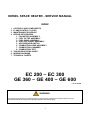
1
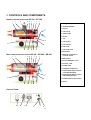
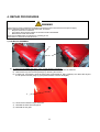
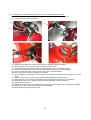
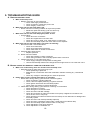
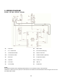
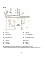
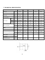
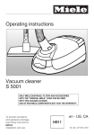
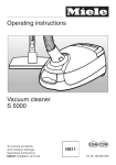
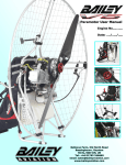
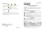
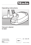
DIESEL SPACE HEATER - SERVICE MANUAL
INDEX
1.
2.
3.
4.
CONTROLS AND COMPONENTS
FLAME CONTROL CYCLES
MAINTENANCE SCHEDULE
REPAIR PROCEDURES
1. FAN MOTOR ASSEMBLY
2. FUEL FILTER ASSEMBLY
3. FUEL PUMP ASSEMBLY
4. ELECTRIC PANEL ASSEMBLY
5. AIR PRESSURE SWITCH
6. COMBUSTION HEAD ASSEMBLY
7. COMBUSTION CHAMBER
8. COMBUSTION TEST
5. TROUBLESHOOTING GUIDE
6. WIRING DIAGRAMS
7. TECHNICAL SHEETS
EC 200 – EC 300
GE 360 – GE 400 – GE 600
L-S 102.00-BM
WARNING
The operations described in this booklet must be carried out by qualified and instructed personnel only.
Incorrect maintenance may result in improper operation and serious injury.
1
1. CONTROLS AND COMPONENTS
INDIRECT HEATER WITH STACK:EC 200 – EC 300
1
2
3
22
21
5
4
6
7
1 COMBUSTION CHAMBER
2 BURNER ASSEMBLY
3 NOZZLE
4 FUEL VALVE
5 DIESEL PUMP
6 MOTOR
7 FAN
8
8 FUEL FILTER
10
9 FUEL CIRCUIT
11
10 FUEL TANK
20
18
9 19
11 FUEL TANK PLUG
12
12 DRAIN PLUG
DIRECT HEATER WITHOUT STACK:GE 360 – GE 400 – GE 600
1
2
3
21
5
4
6
7
13 RESET BUTTON/LAMP OF
CONTROL FLAME
14 MAIN SWITCH
15 ROOM THERMOSTAT PLUG
16 CONTROL LAMP
17 POWER CORD
18 OVERHEAT THERMOSTAT
19 AIR PRESSURE SWITCH GAUGE
(LOW PRESSURE SIDE)
8
10
20 AIR PRESSURE SWITCH GAUGE
(HIGH PRESSURE SIDE)
21 FLAME DETECTOR (PHOTOCELL)
11
22 STACK
18
20
9 19
12
CONTROL PANEL
13
14
15
17
16
2
CONTROL SYSTEM
The heater has all operational controls located in a watertight control panel mounted on the lateral side of the unit.
The control panel consists of:
• a 3-position switch for heating function: normal operation, stop or thermostat operation
• plug to connect a remote room thermostat
• power cord
• high voltage transformer that generates a spark to ignite the flame
• control flame box to handle starting / running cycle (see paragraph 2.).
The control flame box is equipped with a reset
The control system utilizes:
• a safety shut off switch that is a overheat thermostat shutting down the unit if the temperature of combustion
chamber and outlet air exceed the maximum allowed level
• an air pressure switch, that stops the unit if the air flow is not sufficient for combustion.
• a flame detector, that is a photocell monitoring constantly the flame presence and its integrity.
• a pair of ignition rods to create the ignition spark
FUEL SYSTEM
The fuel system consists of:
• fuel tank, that is steel, corrosion proof
The fuel tank hase a drain plug located underneath it to allow discharge of residual fuel before cleaning.
• fuel filter
• fuel pump. A screw fitted on the fuel pump allows the adjustment of fuel pressure setting
• fuel ON/OFF solenoid valve
o during normal operation the valve is open and the pressurized fuel flows to the nozzle, where it is
atomized, mixed with primary combustion air and ignited by the electrode spark
o during abnormal operation (see paragraph 2.) the flame control unit closes the fuel solenoid valve and
the unit stops.
• fuel circuit, including suction and return hoses from fuel tank to fuel pump and high pressure microhose from
fuel pump to nozzle
• burner head
• nozzle
COMBUSTION CHAMBER
For indirect heater it consists of:
• the internal combustion chamber (stainless steel made) that containing the flames and
• the external high efficient heat exchanger (aluminated steel made), that leads smokes to chimney / stack.
For direct heater it consists of the internal combustion chamber (stainless steel made) that containing the flames and
exhanges heat with the main airflow stream.
BURNER HEAD
The burner head is the assembly that determines the correct mixing of combustion air and fuel inside the combustion
chamber and it consists of:
• Fuel nozzle
• Nozzle support
• Flame diffuser
• Air opening baffle: a screw fitted on the burner head allows the adjustment of combustion air setting
• Ignition electrodes
• Flame detector
FAN – MOTOR ASSEMBLY
The electric motor drives the fuel pump assembly and a fan which blows air inside and around combustion chamber.
3
2. FLAME CONTROL RUNNING / FAILURE CYCLE
2.1 STARTING CYCLE
The flame control unit starts the sequence of operation after a heating request (normal operation or thermostat
operation) and it consists of the following steps:
• Self-test (less than 3 s): self-check of electronics efficiency;
• Purging time TP (20 seconds): fan motor and ignition transformer are simultaneously switched on while the fuel
valve remains closed to eliminate any fuel or unburnt residual.
During the purging stage, the flame signal is constantly monitored and any kind of failure leading to combustion
prevents the burner ignition.
In case of heating request opening (room thermostat opening), the control unit goes to stand-by position. The
device remains in this status till closing of the room thermostat;
• Safety time (5 seconds): at the end of the purging time TP, the fuel valve is switched on and opens the fuel to
the nozzle.
In case of flame detection failure by the end of the TS safety time, the control unit goes to lockout, and the fan
motor, the ignition transformer and the fuel valve are de-energized, while the lockout signal is enabled.
Otherwise, at the end of the TS safety time the control unit disables the ignition transformer and goes to running
position.
• At the end of the TS safety time the control unit keeps the ignition transformer operating for about 30 s.
2.2 SHUT OFF CYCLE
When the heating request (normal operation or thermostat operation) opens:
• fuel valve and ignition transformer are switched off and the flame lights off;
• burner fan operates a 90 s post-purge ventilation
Restoring the heating request causes the post-purge to be interrupted and the starting cycle to be performed.
4
2.3 FLAME FAILURE DURING STARTING CYCLE
If during the safety time TS, the photocell monitors a flame failure (signal to photocell become lower than
minimum), at the end of safety time the unit goes in lock out condititon:
• burner fan, ignition transformer and fuel valve are de-energized;
• alarm lamp on reset button becomes red
Unit can re-start only if pressing the reset button
2.4 EXTRANEOUS LIGHT OR FLAME DURING PRE-PURGE TIME TP
If during the pre-purge time the photocell monitors any residual flame then the unit goes in stand-by condition:
• burner fan goes on to purging combustion chamber
• fuel valve and ignition transformer are de-energized
• reset lamp is off;
5
2.5 FLAME FAILURE DURING RUNNING STATUS (ONE TRIAL RECYCLING)
In case of flame failure in running status, the flame control unit make one trial restarting the unit.
If the reason of flame failure is confirmed, then the unit stops in lock-out mode, and the reset lamp becomes red.
2.6 RESET LAMP COLOR
WARNING
The reset button may have different colours:
•
light off: unit is in stand-by status, waiting for heating request.
•
steady orange light: function not active
•
steady green light: unit is working normally (starting cycle or working cycle)
•
steady red light: the heater stops permanently in lock-out status and can restart only if reset button is
pressed.
6
3. MAINTENANCE SCHEDULE
Periodic maintenance of the heater is necessary to ensure proper performance and to prevent failures and it shall be
performed at the following periodic intervals:
• Daily maintenance
i. Inspect air inlet / air outlet and exhaust stack, remove debris if any
ii. If any air hose is installed, secure it is fixed. Minimize bends and keeps ducts straight
iii. Verify fuel tank is full
iv. Verify that exhaust stack is properly installed
• Weekly maintenance
i. Disassemble, inspect and clean fuel filter with clean fuel
ii. Remove top cover and clean the motor, fan blade and the interior shell
iii. Inspect the fuel hose assembly and check for any leaks
• 6 months maintenance
i. Disassemble burner head
1. Inspect and clean burner diffuser
2. Inspect and replace nozzle if necessary
3. Clean ignition electrodes and adjust settings
4. Check air combustion setting
ii. Check overheat thermostat
iii. Inspect and clean the combustion chamber
iv. Open electric board, inspect electrical components and check connections
v. Check fuel pressure setting of fuel pump
vi. Inspect and test the burner
7
4. REPAIR PROCEDURES
WARNING
Before carrying out any maintenance operation the heater must be disconnected from power supply.
Refer to instruction manual to fully stop the heater. Therefore:
• Stop the machine as instructed
• Turn off the disconnecting switch on the main electric switchboard
• Wait until the heater has cooled.
Never service heater while it is plugged in, operating or hot.
Severe burns or electrical shock can occur.
1) FAN MOTOR ASSEMBLY
a
b
a) To clean the fan blades and motor, carry out the following procedure.
i) Remove the air inlet grille (a) by removing four screws that secure it to the machine.
ii) Remove the top cover access panel (b) by removing four screws
iii) Inspect and, if necessary, clean the motor using compressed air, being carefully not to direct the air jet to
the air pressure switch gauge (c) (the pressure switch could be damaged)
c
iv) Clean the fan blades using a stiff brush.
v) Reinstall the internal access panel.
vi) Reinstall the fan grille.
8
b) To replace the fan blade and the electric motor, carry out the following procedure.
i) Remove the air inlet grille (a) by removing four screws that secure it to the machine.
ii) Loosen the screw (d) on the fan hub
d
e
f
iii)
iv)
v)
vi)
vii)
viii)
ix)
Extract the fan blades and replace with a new one respecting blades orientation
Remove the top cover access panel (b) by removing four screws
Loosen three screws (e) on the fuel pump casing (be sure not to remove the screws)
Remove fuel pump from electric motor and keep plastic coupling for next reassembling
Loosen and remove eight screws (f) that fix the motor on the motor flange
Open main electric board on side/front of the heater
Trace the electric motor power cords and disconnect the three wires (white, black, green) from control
panel
x) Position a new motor on the motor flange and reassemble eight screws (f) to fix it
xi) Check alignment of the motor to the heater axis and tighten eight screws (f) on motor flange
xii) Reassemble fuel pump on electric motor being sure that plastic coupling is aligned
xiii) Tighten three screws (e)
xiv) Position fan blade on the motor shaft being sure there is no interference with any parts when rotating
xv) Tighten screw (d) and check free rotation of the fan blades
xvi) Reinstall the fan grille and the top cover.
9
2) FUEL FILTER ASSEMBLY
a) To clean / replace the pre-heated type fuel filter, carry out the following procedure.
i) Remove the screw (a) that secures the cover to the housing and remove o-ring (b)
b
a
c
e
ii)
iii)
iv)
v)
vi)
vii)
viii)
Using a suitable container, collect the fuel when removing from the fuel filter assembly
Remove the fuel cell (c) and wash it with clean diesel oil
If necessary replace the fuel cell (c)
If necessary to replace the heating element, loosen the nut (d) and remove the electric resistance (e)
Inspect the o-ring, replace it if it is cracked, damaged, or deformed
Reassemble the filter assembly checking the o-ring is placed in the right position
Tighten screw (a)
10
b) To clean / replace the standard type fuel filter, carry out the following procedure.
i) Loosen the casing (a) that secures to the housing
b
c
a
ii)
iii)
iv)
v)
vi)
vii)
Using a suitable container, collect the fuel when removing from the fuel filter assembly
Remove fuel cell (c) and o-ring (b) and wash with clean diesel oil
If necessary replace the fuel cell (c)
Inspect the o-ring, replace it if it is cracked, damaged, or deformed
Reassemble the filter assembly checking the o-ring is placed in the right position
Tighten casing (a) by hand, checking the o-ring is pressed
3) FUEL PUMP ASSEMBLY
a) To replace fuel pump, carry out the following procedure.
b
e
i)
ii)
iii)
iv)
v)
vi)
vii)
Remove the top cover access panel (b) by removing six screws
Loosen three screws (e) on the fuel pump casing (be sure not to remove the screws)
Remove fuel pump from electric motor and keep plastin coupling for next reassembling
Disconnect wires lead to fuel solenoid valve (g)
Reassemble new fuel pump on electric motor being sure that plastic coupling is aligned
Tighten three screws (e)
Reinstall the top cover.
11
g
b) To set fuel pressure on fuel pump, carry out the following procedure.
a
b
i) Remove the top cover access panel (b) by removing six screws
ii) Loosen cap (a) on front of fuel pump and connect a fuel pressure meter
iii) Disconnect wires lead to fuel solenoid valve (to avoid fuel spray inside combustion chamber)
WARNING
The following operation shall be done with top cover and possible access to rotating fan.
Fan rotating area is covered by fan support even if accessible
Take measure to avoid touching any rotating parts while setting fuel pressure
iv)
v)
vi)
vii)
viii)
Start the heater and check the fuel pressure be the value listed in the final technical sheet
Correct the pressure by screwing (to increase pressure) or unscrewing (to decrease pressure) screw (b)
Remove fuel pressure meter and tighten cap (a)
Connect wires to solenoid fuel valve
Reinstall the top cover.
4) ELECTRIC PANEL ASSEMBLY
a) To check electric control board, carry out the following procedure.
i) Remove two screws (a) on front/side of heater
ii) Remove top cover (b) of electric board
b
a
12
iii) Check that all connections are complete and tight
iv) Reassemble top cover (b) and fix electric board to the heater
5) AIR PRESSURE SWITCH
a) To check / replace air pressure switch, carry out the following procedure.
i) Remove four screws (a) on side of heater
a
ii)
iii)
iv)
v)
Pull air pressure switch assembly out of the base
Check silicon tube are not pinched and tightened to connectors
Check there is no debris inside silicon tube
Reassemble pressure switch assembly and tighten screws (a)
6) COMBUSTION HEAD ASSEMBLY
a) To clean combustion head assembly, carry out the following procedure.
i) Remove the top cover access panel (b) by removing six screws
b
a
c
ii)
Loosen screw (a) and remove fast-on connector of yellow/green wire)(c)
13
iii) Turn counterclockwise burner support (d) and pull it out of burner tube (e)
d
e
e
g
f
iv) Check / Clean diffuser ring (f)
(1) be sure any debris or soot is eliminated every wing and opening on front surface of ring
(2) if necessary loosen screw (f) and remove it to wash using clean diesel
(3) check for any damage or bended part: if any replace it
v) Check / clean ignition electrodes (g)
(1) Clean and remove any debris or soot on sharp ends of electrodes
(2) If necessary remove both electrodes and replace
(3) Check alignment as by following image: electrodes shall be centered and symmetric
(4) Check electrode connectors (h) be tightened and clean
14
h
vi) Check/replace fuel nozzle
(1) Refer to technical data sheet for specific indication of nozzle type
(2) Remove electrodes (g)
(3) Remove diffuser ring (f)
(4) Loosen fuel nozzle and place a new one
(5) Reassemble diffuser ring and electrodes taking care of each correct positioning as by previous
instructions
vii) Check / clean photocell
(1) Remove photocell (i) and check it is clean
(2) Check photocell support be clean and clean hole (m)
i
m
viii) Check / adjust air openings
(1) Loosen nut (n)
(2) Adjust lever (p) until the requested opening is obtained (check final tech. sheet)
15
n
p
ix) Reassemble combustion head
x) Reassemble top cover
7) COMBUSTION CHAMBER ASSEMBLY
a) To clean combustion chamber assembly, carry out the following procedure.
i) Remove the top cover access panel (b) by removing six screws
b
a
c
ii)
iii)
iv)
v)
vi)
Loosen and remove three nuts (a)
Remove the burner head tube assembly (c)
Check and clean inside combustion chamber with a cloth, removing liquid fuel residual
Reassemble burner head tube assembly (c)
Reassemble top cover (b)
16
8) COMBUSTION TEST (HEATER WITH FLUE ONLY)
a) To check combustion smoke index with Shell-Bacharach method, carry out the following procedure.
i) Use a standard Bacharach pump (a).
ii) Insert a test strip (b) into the pump slot.
iii) Insert the pump end into the flue connection (c) or flue extension.
c
b
a
d
iv) Start the heater and wait five minutes until it operates in standard conditions
v) Pump in exhaust gases for 10 times, taking care to carry out all movements slowly and using the
complete piston stroke.
vi) Extract the paper strip, check the colour and compare it with the reference scale (d) to assign a smoke
number:
(1) Oil-fired heaters are tested and set by factory to give a smoke number equal to 0 (zero) of the ShellBacharach scale.
(2) A smoke number greater than 1 indicates bad combustion. Refer to following troubleshooting guide
to find the causes of the problem and to correct them.
17
5. TROUBLESHOOTING GUIDE
A. HEATERS DOES NOT START
a. Main control lamp is off
i. Missing connection to main supply line
1. Check main supply is switched on
2. Check connection of extension power cord
3. Check integrity of main fuse
b. Motor does not run and reset lamp is red
i. Flame control box in locking condition for a previous problem
1. Reset and repeat the starting cycle once time only.
2. Refer to following if any new problem occurs
c. Motor does not run and reset lamp light up after 30 secs
i. Air flow failure
1. Check fan motor connections
2. Check fan is tightened on fan motor axle
3. Check fan is free to rotate: if not, make service on fuel pump
4. Check and eventually replace fan motor and/or motor capacitor.
d. Motor does not run and reset lamp is off (unit is in stand-by)
i. Room thermostat / main switch failure
1. Check room thermostat
2. Check room thermostat connections
3. Check main switch on heater control board
ii. Photocell failure (short circuit)
1. Replace photocell
iii. Flame control box failure
1. Check fuse integrity on flame control box
2. Check wiring connection and eventually replace flame control box
iv. Voltage lower than 70 V or higher than 150 V
1. Check supply voltage is correspondant to rating plate.
2. Unit will automatically restart when voltage becomes higher than 80 V or lower than 140 V.
B. HEATER STARTS BUT DOES NOT COMPLETE STARTING CYCLE
a. Motor runs continuously, there are no flame and reset lamp is off
i. Extraneous light or flame during pre-purge cycle
1. Check positioning of photocell
2. Make service of combustion head and combustion chamber removing any residual fuel
inside
3. Check any sunlight or external light can reach the photocell
b. Heater stops in lock- out and reset lamp is on (red light)
i. Flame failure during starting cycle because of incorrect ignition
1. Check connection of ignition electrode
2. Check, clean and adjust positioning of ignition electrode
3. Check ignition transformer and eventually replace
4. Check main connections to ignition transformer
ii. Flame failure during starting cycle because of missing / incorrect flame
1. Check fuel tank is not empty
2. Check fuel type be correct and clean
3. Check and clean fuel filter cartridge
4. Check all connections of fuel line from tank to fuel pump: untightened connections can
cause suction of air to fuel pump
5. Check fuel line (from to/the fuel tank and to the nozzle) are not obstructed or damaged and
eventually replace
6. Check and clean fuel nozzle (eventually replace it)
7. Check and clean combustion head (nozzle, nozzle support and diffuser disc)
8. Check and eventually replace solenoid valve on fuel pump
9. Check adjustment of fuel pump pressure
10. Check adjustment of combustion air
18
C. HEATER STARTS BUT IT DOES NOT RUN REGULARLY
a. Heater stops in lock-out and reset lamp is on (red light)
i. Flame failure because of missing fuel
1. Check fuel tank not be empty
2. Check fuel type be correct, clean without water
3. Check and clean fuel filter cartridge
4. Check all connections of fuel line from tank to fuel pump: untightened connections can
cause suction of air to fuel pump
5. Check fuel line are not obstructed or damaged and eventually replace
6. Check adjustment of fuel pump pressure
ii. Flame failure because of bad combustion
1. Check and clean fuel nozzle (eventually replace it)
2. Check and clean combustion head (nozzle, nozzle support and diffuser disc)
3. Check adjustment of fuel pump pressure
4. Check adjustment of combustion air
iii. Flame failure because of air pressure switch PA cutting in
1. Check fan is tightened on fan motor axle
2. Check there is no object obstructing air inlet
3. Check hose to air pressure switch are not obstructed
4. Check connections to electrical wirings of air pressure switch
5. Check and eventually replace air pressure switch
iv. Flame failure because of safety thermostat LI cutting in
1. Check there is no object obstructing air outlet
2. Check air outlet hose respect maximum length and diameter as specified
3. Check connections to electrical wirings of overheating thermostat
4. Check and eventually replace safety thermostat
b. Heater stops in stand-by and reset lamp is off
i. Voltage lower than 70 V or higher than 150 V
1. Check supply voltage is correspondant to rating plate.
2. Unit will automatically restart when voltage becomes higher than 80 V or lower than 140 V.
c. Heater starts and stops flames and main fan remains on (unit is in stand-by and reset lamp is off)
i. Air bubbles in the suction line to fuel pump
1. Check oilf filter casing is tightened
2. Check check all connection on fuel line to fuel pump are tightened
3. Check fuel line are not obstructed
4. Check fuel tank level
D. HEATER RUNS WITH BAD COMBUSTION AND EVENTUALLY WITH WHITE OR BLACK SMOKES
a. Heater runs with white smokes
i. Fuel /air mixing on combustion head is incorrect: excess air or few fuel
1. Check adjustment of fuel pump pressure
2. Check adjustment of combustion air
b. Heater runs with black smokes
i. Fuel /air mixing on combustion head is incorrect: few air or excess fuel
1. Check adjustment of fuel pump pressure
2. Check adjustment of combustion air
c. Heater runs with noisy / irregular combustion with/without smokes
i. Combustion is incorrect
1. Check and clean fuel nozzle (eventually replace it)
2. Check and clean combustion head (nozzle, nozzle support and diffuser disc)
3. Check exhaust is not obstructed
4. Check combustion chamber is not clogged by soot and eventually wash and clean it
19
E. WHEN SWITCHING OFF, HEATER DOES NOT STOP
a. Heater still runs with flame
i. Room thermostat / main switch failure
1. Check room thermostat and room thermostat connections
2. Check main switch on heater control board
ii. Fuel flow to nozzle is not interrupted
1. Check fuel solenoid valve is closing fuel line to nozzle
20
6. WIRING DIAGRAM
EC 200 – EC 300 – GE 360 – GE 400
FU
Fuse 20 A
RV
Main switch
IT
H.T. Transformer
TA
Room thermostat plug
LI1
Overheat thermostat
AP
Flame control box
EV1
Fuel solenoid valve
RF
Heated fuel filter (optional)
FO
Photocell
PA
Air pressure switch
CO
Capacitor
FUA
Fuse 6,3 A
MV
Fan motor
RE
RELAY
ST
Control lamp
FU
FUSE 20 A
NOTE
Air pressure switch PA and overheating thermostat LI1 are connected in serie to fuel valve EV1.
Therefore in case PA and LI1 opens, the fuel valve EV1 is switched off and the flame control unit goes in lock-out in
the “flame failure mode”.
21
GE 600
FU
Fuse 20 A
RV
Main switch
IT
H.T. Transformer
TA
Room thermostat plug
LI1
Overheat thermostat
AP
Flame control box
EV1
Fuel solenoid valve
RF
Heated fuel filter (optional)
FO
Photocell
PA
Air pressure switch
CO
Capacitor
FUA
Fuse 6,3 A
MV
Fan motor
RE
RELAY
ST
Control lamp
FU
FUSE 20 A
NOTE
Air pressure switch PA and overheating thermostat LI1 are connected in serie to fuel valve EV1.
Therefore in case PA and LI1 opens, the fuel valve EV1 is switched off and the flame control unit goes in lock-out in
the “flame failure mode”.
22
7. TECHNICAL SPECIFICATION
TECHNICAL SPECIFICATIONS
Heat input
Air flow
Heat output
Fuel consumption
EC 200
EC 300
GE 360
GE 400
GE 600
[kBTU/h]
204.873
293.982
361.439
396.376
599.524
[cfm]
1,530
2,531
1.795
2.500
2.800
[kBTU/h]
183.362
258.704
-
-
-
[gal/h]
1.48
2.17
2.60
2.83
4.32
1
1
1
1
1
Phase
Power supply
Voltage
[V]
120
120
120
120
120
Frequency
[Hz]
60
60
60
60
60
[W]
785
1.330
632
1,170
1,240
[A]
7.65
11.80
6.00
7.50
11.10
[USgal/h]
1.10-80° W
[psi]
174
174
174
203
203
[in]
a=0.196
a=0.236
a=0.394
a=0.709
a=0.866
N°
A=3.5
A=4
A=5.0
A=7.5
A=3.5
[in WC]
0.5
0.5
-
-
-
[in]
5.9
5.9
-
-
-
[in WC]
0.05
0.05
-
-
-
Electric consumption
Nozzle
Pump pressure
1.50-80° W
2.00-80° W
2.00-80° W
3.00-80 ° S
Adjustment of combustion air flap
Static pressure
Flue diameter
Compulsory flue draft
23