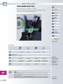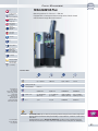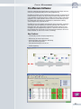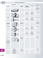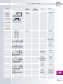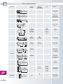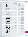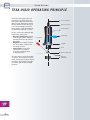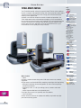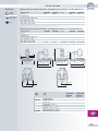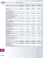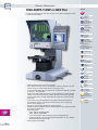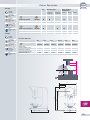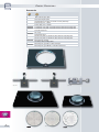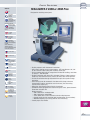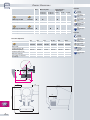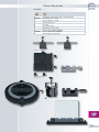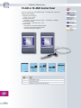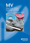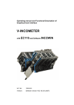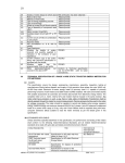
1
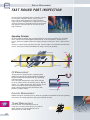
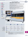
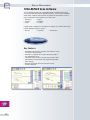
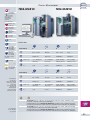
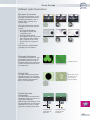
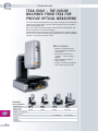
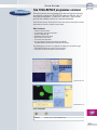
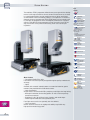
P-1
Optical Measurement
PROFILE MEASUREMENT
FAST ROUND PART INSPECTION
The whole TESA-SCAN family offers a complete solution
for round part inspection. Various systems such as
those used on profile projectors or measuring microscopes have been integrated into a single unit. This range
of TESA’s products are designed to measure round parts
with diameters from 0,25 up to 52 mm and can be as
long as 500 mm.
Operating Principle
All TESA-SCAN incorporate high-resolution CCD linear sensors that combine lines of 14 000
pixels (equivalent to a 200 megapixels CCD camera). As the part profile is projected, these
sensors, which are capable to detect the slightest changes at pixel level, act as a light sensitive
ruler.
The part is scanned using a parallel green light. The part image is then projected onto the linear
sensors, which get all needed information for analysis of the part geometry.
SENSOR 1
MACHINED PART
WORKPIECE
IMAGE
LIGHT
SOURCE
CONDENSER
LENS
PROJECTOR LENS
SENSOR 2
2D Measurement
The part profile is obtained from a scanning method
applied along the part axis. Both diameter and length of
the part are measured simultaneously, thus producing
a 2D video image.
One of the main characteristics of the TESA’s concept
lies in the slanted position of the linear sensors. With an
angle to 7,5° against the part axis, these sensors ensure
a precise data capture when inspecting diameters,
angles, radii and other geometric part features with
parallel or slopped surfaces.
Dynamic Measurement
Rotation during the inspection process allows for a peripheral examination of the part geometry
and contour, each being captured at high speed and high accuracy.
Thread Measurement
External threads are an important feature of
round parts, and their measurement is an intensive
labour operation. A true thread profile can be
obtained from any TESA-SCAN.
PP-2-2
PROFILE MEASUREMENT
TESA-SCAN 52 REFLEX-Click
✓
HxLxD
840 x 1000 x
435 mm or
33 x 39,5 x 17 in
0,5 s for
lengths and
diameters
This model includes the ultimate power of all TESA-SCAN machines, offering
high technological performances combined with unmatched ease of use and
exceptional price/quality relationship.
Thanks to the added functionality for automatic recognition of the parts
to be measured, the REFLEX-Click mode allows them to be quickly and reliably inspected with a single click. The colour coded classification of the
measured values enables the analysis of the measurement results at a glance,
rendering part inspection especially easy to execute.
Performances:
see page P-4
Another unique function available in the REFLEX-Click mode is the ability
to measure lengths and diameters speedily, making the machine ideally
suited for use on the shop floor.
24 VDC
10 to 40 °C
< 80%
✓
103 kg
Max. workpiece
size (D x L):
100 x 300 mm.
Max. workpiece weight: 4 kg.
< 70 dB (A)
Shipping packaging
Inspection report
with a declaration
of conformity
Performances
are based on
the results obtained
from clean, ground
components
measured at 20°C.
They may be
affected by the
component shape
and surface finish.
D
L
D
L
0,5 ÷ 52 mm
300 mm
0,02 ÷ 2.0 in
11.8 in
0,0001 mm
0,0005 mm
0.000004 in
0.00002 in
20°C ± 1°C
(2 + D/100) µm
(D in mm)
(5 + L/100) µm
(L in mm)
(0.08 + D/100) /
1000 in (D in in)
(0.2 + L/100) /
1000 in (L in in)
2σ
1 µm
2,5 µm
0.00004 in
0.0001 in
02430090
02430091
TESA-SCAN 52 REFLEX-Click (Ø 52 x 300 mm). Measuring machine including 2 male centres
TL02-0001. Supplied with PC, mouse, US keyboard, Windows XP Multilingual operating
system, 20-inch TFT monitor.
TESA-SCAN 52 REFLEX-Click with rotary headstock
P-3
PROFILE MEASUREMENT
TESA-REFLEX Scan Software
The TESA-REFLEX family has expanded through the addition of the Scan
version provided with intuitive graphical interface. The use of the Composer
mode allows complex measurements of geometrical part features such as
those listed below to be carried out in a simple way.
• Diameters
• Lengths
• Radii
• Angles
• Chamfers
• Threads
Equipped with a rotation axis available as an option, this machine will let you
inspect additional features such as:
• Runout
• Coaxiality
• Across-flats
Key Features
• Automatic measurement of lengths and diameters using
the REFLEX-Click function.
• Automatic recognition of the parts being measured or
the programmes used.
• Intelligent detection of the relevant measurement zones.
• Management of the operator and programming modes.
• Value storage.
• Dynamic displaying of the measurement results.
• Flexible reporting.
P-4
PROFILE MEASUREMENT
✓
TESA-SCAN 25
TESA-SCAN 50
TESA-SCAN 25:
H800 x L640 x
P500 mm,
H32 x L25 x P20 in
TESA-SCAN 50:
H1055 x L800 x
P580 mm,
H41 x L32 x P23 in
Diameter : 0,5 s
Length : 0,5 s
Performances:
see page P-8
100/110220/240 VAC
50/60 Hz
10 to 35 °C
50 to 95 °F
< 80%
✓
TESA-SCAN 25:
67 kg, 148 lbs
TESA-SCAN 50:
130 kg, 290 lbs
Max. workpiece
size (D x L):
59 x 270 mm;
100 x 290 mm.
Max. workpiece weight:
2 kg; 4 kg.
< 70 dB (A)
Shipping packaging
Inspection report
with a declaration
of conformity
Technical Data
D
L
D
L
0,25 ÷ 25 mm
200 mm
0,01 ÷ 1.0 in
8.0 in
0,0001 mm
0,001 mm
0.000004 in
0.00004 in
20°C ± 1°C
(1,5 + D/100) µm
(D in mm)
(5 + L/100) µm
(L in mm)
(0.06 + D/100)/
1000 in (D in in)
(0.2 + D/100)/
1000 in (L in in)
2σ
1 µm
2,5 µm
0.00004 in
0.0001 in
D
L
D
L
0,5 ÷ 50 mm
275 mm
0,02 ÷ 1.96 in
10.8 in
0,0001 mm
0,001 mm
0.000004 in
0.00004 in
20°C ± 1°C
(2 + D/100) µm
(D in mm)
(5 + L/100) µm
(L in mm)
(0.08 + D/100)/
1000 in (D in in)
(0.2 + D/100)/
1000 in (L in in)
2σ
1 µm
2,5 µm
0.00004 in
0.0001 in
TESA-SCAN 25
TESA-SCAN 50
Performances
are based on
the results obtained
from clean, ground
components
measured at 20 °C.
They may be
affected by the
component shape
and surface finish.
02430000
02430010
For information
on Pro-Measure,
see page P-9.
TESA-SCAN 25 (Ø 25 x 200 mm). Measuring machine with part rotation, including 1 rotary
headstock, 1 tailstock, 2 male centres TL02-0001.
Supplied with PC, mouse, Windows XP Multilingual operating system, 20-inch TFT monitor,
US keyboard, Pro-Measure software with User’s manual E-F-D on a CD (order No. 02460011).
TESA-SCAN 50 (Ø 50 x 275 mm). Measuring machine with part rotation, main part including
1 rotary headstock, 1 tailstock, 2 male centres TL02-0002.
Supplied with PC, mouse, Windows XP Multilingual operating system, 20-inch TFT monitor,
US keyboard, Pro-Measure software with User’s manual E-F-D on a CD (order No. 02460011).
P-5
PROFILE MEASUREMENT
TESA-SCAN 50 CE Plus
✓
Measuring capacity : D = 50 mm, L = 275 mm
H1055 x L800 x
P580 mm
H41 x L32 x P23 in
Equipped with slewing mechanism for thread measurement through
advanced functions (slide tilted through 30°) .
Diameter : 0,5 s
Length : 0,5 s
Performances:
see page P-8
100/110220/240 VAC
50/60 Hz
10 to 35 °C
50 to 95 °F
< 80%
✓
140 kg, 310 lbs
Max. workpiece
size (D x L):
100 x 290 mm.
Max. workpiece weight: 4 kg.
< 70 dB (A)
Shipping packaging
Inspection report
with a declaration
of conformity
Technical Data
Tilting for thread
measurement
L
D
L
0.5 ÷ 50 mm
275 mm
0,02 ÷ 1.96 in
10.8 in
max. 30°
0,0001 mm
0,001 mm
0.000004 in
0.00004 in
20°C ± 1°C
(2 + D/100) µm
(D in mm)
(5 + L/100) µm
(L in mm)
(0.08 + D/100)/
1000 in (D in in)
(0.2 + D/100)/
1000 in (L in in)
2σ
1 µm
2,5 µm
0.00004 in
0.0001 in
02430030
P-6
D
TESA-SCAN 50 CE Plus (Ø 50 x 275 mm). Measuring machine with part rotation and slewing
mechanism for thread measurement. Main part including 1 rotary headstock, 1 tailstock, 2 male
centres TL02-0002.
Supplied with PC, mouse, Windows XP Multilingual operating system, 20-inch TFT monitor,
US keyboard, Pro-Measure software with User’s manual E-F-D on a CD (order No. 02460011).
Performances
are based on
the results obtained
from clean, ground
components
measured at 20 °C.
They may be
affected by the
component shape
and surface finish.
For information
on Pro-Measure,
see page P-9.
PROFILE MEASUREMENT
✓
TESA-SCAN 50 Plus
H1455 x L800 x
P580 mm
H57 x L32 x P23 in
Measuring volume: D = 50 mm, L = 500 mm
Equipped with a slewing mechanism acting on the slide for thread
measurement through advanced functions.
Diameter : 0,5 s
Length : 0,5 s
Performances:
see page P-8
100/110220/240 VAC
50/60 Hz
10 to 35 °C
50 to 95 °F
10 to 80%
✓
180 kg, 398 lbs
Max. workpiece
size (D x L):
100 x 515 mm.
Max. workpiece weight: 6 kg
< 70 dB (A)
Shipping packaging
Inspection report
with a declaration
of conformity
Technical Data
D
L
D
L
0,5 ÷ 50 mm
500 mm
0,02 ÷ 1.96 in
19.7 in
0,0001 mm
0,001 mm
0.000004 in
0.00004 in
20°C ± 1°C
(2 + D/100) µm
(D in mm)
(5 + L/100) µm
(L in mm)
(0.08 + D/100)/
1000 in (D in in)
(0.2 + D/100)/
1000 in (L in in)
2σ
1 µm
2,5 µm
0.00004 in
0.0001 in
Tilting for thread
measurement
Performances
are based on
the results obtained
from clean, ground
components
measured at 20 °C.
They may be
affected by the
component shape
and surface finish.
02430040
For information
on Pro-Measure,
see page P-9.
max. 15°
TESA-SCAN 50 Plus (Ø 50 x 500 mm). Measuring machine with part rotation and slewing mechanism for thread measurement. Main part including 1 rotary headstock, 1 tailstock, 2 male centres
TL02-0002.
Supplied with PC, mouse, Windows XP Multilingual operating system, 20-inch TFT monitor,
US keyboard, Pro-Measure software with User’s manual E-F-D on a CD (order No. 02460011).
P-7
PROFILE MEASUREMENT
Performances
(Valid for the TESA-SCAN 25 or TESA-SCAN 50 product range)
Static measurement
Diameters, lengths, intersection points, gauge diameters, radii, angles etc.
Two-axes workpiece alignment – Creating a workpiece axis based on two datum diameters.
Dynamic measurement
Concentricity – Parallel or interrupted diameters, tapers, parallel thread profiles or
on maxi form.
Runout – Plain or interrupted diameters.
Diameters with rotation, ovality, max, min and average diameters of plain or interrupted
diameters.
Hexagon – Across-flats, symmetry of flats to axis, max. dimension across corners.
Section analysis with rotation – Longest and shortest section of radii, angular location.
Three-axes workpiece alignment – Creating a workpiece axis with reference to plain
diameters or thread lengths.
Thread measurement – With no mechanical slewing –
Main Features (TESA-SCAN 25 or TESA-SCAN 50)
• Parallel, vee-shaped threads
– Major diameter
– Flank diameter
– Flank angle
– Pitch
• Taper threads
– Pitch
– Flank angle
– Included taper angle
– Gauge length
– Usable thread length
– Pitch diameter
– Major diameter
– Conicity on diameter
Thread and worm thread measurement – With mechanical slewing –
Main Features (TESA-SCAN 50 CE plus or TESA-SCAN 50 plus)
P-8
•
–
–
–
–
–
–
–
–
–
Parallel threads
Major diameter
Flank diameter
Pitch
Minor diameter
Flank angle
Root radius
Crest radius
Circularity
Lead error
•
–
–
–
–
–
Taper threads
Pitch diameter
Major diameter
Minor diameter
Taper
Crest diameter
•
–
–
–
–
–
Double-threads, parallel
Major and minor diameters
Half pitch
Flank angle
Crest radius
Root radius
•
–
–
–
–
–
–
–
–
–
Worm threads (on request)
Pitch
Major and minor diameters
Over Wire diameter
Tooth thickness
Pressure angle
Addendum
Dedendum
Thread depth
Runout
•
–
–
–
Ball screws (on request)
Pitch
Lead error
Over wire diameter
PROFILE MEASUREMENT
Pro-Measure Software
Complex metrology-based applications involving form and shape measurement are easily performed due to a flexible programming.
Pro-Measure enables a visual comparison of the true form as captured. This
function makes the analysis of any existing manufacturing problems easier.
It also provides the operator with the needed assistance when creating part
programs. This simple software tool can either be installed directly on the
PC coupled with the machine or networked to a workstation enabling
a part program to be prepared off-line.
Pro-Measure uses the graphic representation of the part profile, created by
scanning the part or importing the required geometry from a CAD file. A
library of icons, each representing a geometric function, guides the user
throughout the part programming sequence. Tolerance and setting values
for cylindrical parts or threads can be retrieved from a database of international standards in order to be entered, accordingly.
Key Features
• User-friendly interface for part programming.
• Wide variety of measuring functions.
• Statistical follow up for optimum monitoring
of the manufacturing process.
• Full control of multiple levels of use.
• Flexible reporting.
P-9
PROFILE MEASUREMENT
Accessories
Order Number
TL01-0002
Morse 2
TESA-SCAN 50
TESA-SCAN 52 REFLEX-Click
Notes
●
–
–
Centre adapter
with a 6 mm dia.
coupling bore
●
●
Requires
TL01-0027
External
clamping
for manual
use
Two-jaw gripper
●
●
Requires
TL01-0027
External
clamping
for use with
air pressure
Two-jaw gripper
For
TL01-0003
TL01-0004
–
–
Raising blocks
for external jaws,
in pairs
●
●
Requires
TL01-0027
Internal
clamping
for manual
use
Two-jaw gripper
●
●
Requires
TL01-0027
Internal
clamping
for use with
air pressure
Two-jaw gripper
For
TL01-0003
TL01-0004
–
–
External jaws,
in pairs
For
TL01-0003
TL01-0004
–
–
External jaws,
in pairs
Ø6
MK1
Morse 1
TESA-SCAN 25
Description
57,7
Ø 56
TL01-0003
44
55
Ø 56
TL01-0004
H
TL01-0005
H = 18
TL01-0006
H = 22
14
Ø 56
TL01-0007
P-10
-10
D
B
Ø
TL01-0009
0÷6 mm T = 1,5
TL01-0010
0÷6 mm T = 3
TL01-0011
6÷12 mm T = 3
TL01-0012
12÷18 mm T = 6
TL01-0013
18÷24 mm T = 9
TL01-0038
0÷6 mm T = 6
TL01-0039
0÷6 mm T = 15
TL01-0040
6÷12 mm T = 15
TL01-0021
T
Ø 56
TL01-0008
Set of jaws
including :
TL01-0009
TL01-0010
TL01-0011
TL01-0012
TL01-0013
PROFILE MEASUREMENT
Morse 1
TESA-SCAN 25
Morse 2
TESA-SCAN 50
TESA-SCAN 52 REFLEX-Click
Notes
TL01-0015
D = 4-5 mm
H = 6,6 mm
TL01-0016
D = 5-6 mm
H = 8,6 mm
TL01-0017
D = 6-8 mm
H = 11,5 mm
TL01-0018
D = 8-11 mm
H = 17,5 mm
TL01-0019
D = 11-15 mm
H = 20 mm
TL01-0020
D = 15-19 mm
H = 20,2 mm
TL01-0022
For
TL01-0007
TL01-0008
–
–
For
TL01-0007
–
–
Internal jaws,
in pairs
–
●
–
Centre adapter
with a 6 mm dia.
coupling bore
–
●
–
Reduction
sleeve,
Morse 2 to 1
●
–
2 items
provided with
TESA-SCAN 25
Extra male
centre,
10 mm
–
●
2 items
provided with
TESA-SCAN 50 and
TESA-SCAN 52
Reflex-Click
Extra male
centre,
17 mm
●
–
Diamond
coated
10 mm
Drive
centre
●
–
For added
sleeves
Z1730922/0923
Rotation centre
with a B12 male
taper plus a
Morse 1 taper
shank
H
Order Number
Description
Internal jaws,
in pairs
D
TL01-0026
Ø6
Set of jaws
including :
TL01-0015
TL01-0016
TL01-0017
TL01-0018
TL01-0019
TL01-0020
MK2
80
TL01-0027
MK2
MK1
TL02-0001
MK1
Ø 12
92
17.3
53.5
TL02-0002
Ø 17
MK2
21.6
64
Ø 12
TL02-0003
MK1
53.5
TL02-0016
17.3
MK1
P-11
PROFILE MEASUREMENT
Order Number
TL02-0017
Morse 2
TESA-SCAN 50
TESA-SCAN 52 REFLEX-Click
Notes
–
●
–
Ø 18
Ø 29
MK2
Morse 1
TESA-SCAN 25
Rotation centre,
Morse 2
22
17
68
MK2
–
●
–
TL02-0019
MK1
●
–
–
–
●
Ø 12
Ø 22
TL02-0018
17
12.5
17.780
Rotation centre
with a B12
male taper plus
a Morse 1 shank
Rotation centre,
Morse 1
57
TL02-0021
–
42
Rotation centre,
Morse 2
MK2
61
Z173-0908
Description
56
50
Ø 12.25
For
TL01-0003
TL01-0004
TL01-0007
TL01-0008
–
●
Requires
TL01-0002
●
Requires
TL01-0026
–
●
Requires
TL01-0002
●
Requires
TL01-0026
–
●
Requires
TL02-0016
–
–
●
Requires
TL02-0016
–
●
–
Ø 10
Ensures
stable
positioning
for
mounting
jaws
Vertical
support
Ø 76
Ø 12
Ø6
Z173-0920
10
20
3
Ø 22
Ø6
Z173-0921
14
20
Ø 22
Ø 12
8
3∞
Ø 22
9
Z173-0961
Female centre,
10 mm dia.
Also with internal
B12 taper
3
19
Z173-0923
Female centre,
20 mm dia.
5
3∞
Z173-0922
Female centre,
10 mm dia.
–
Female centre,
10 mm dia.
Also with internal
B12 taper
5
19
MK1
–
Ø 30
Platten,
30 mm dia.
10
55
Z173-2020
●
●
Requires
TL01-0027
Clamping
capacity :
outside
1÷15 mm
inside
11÷26 m
–
●
–
●
–
–
Ø 55
Ø 57
MK1
60
Z173-2025
P-12
Ø 57
Ø 55
Z173-2024
3-jaw chuck,
clamping range
1÷15 mm
6-jaw chuck ,
clamping range
0,7÷15 mm
PROFILE MEASUREMENT
Morse 1
TESA-SCAN 25
Morse 2
TESA-SCAN 50
TESA-SCAN 52 REFLEX-Click
Notes
Z178-2009
–
●
Used to drive
components
between
fixed centres.
Directly fitted
on the
headstock.
Ø 100
Order Number
Z178-2020
–
●
–
●
Ø 72
MK2
33
13.6
98.5
Z178-2025
Clamping
capacity :
outside
2÷50 mm
inside
23÷50 mm
–
Ø 80
Ø 42
MK2
38
–
●
Diamond
coated
–
●
–
–
●
–
●
Requires
TL02-0018
–
●
Requires
TL02-0018
–
●
Requires
TL02-0018
–
●
–
88
Z178-0607
Ø 46
MK2
25
12
85
Z178-0610
84
23
Z178-0940
–
3- 00,5
Z178-0941
90∞
Ø 35
–
0
8 -0,5
43
12
0
- 0,5
–
Female centre,
10 mm dia.,
Also with a B12
internal taper
Female centre,
10 mm dia.,
Also with a B12
internal taper
ø30
50
Ø 42
–
MK2
Female centre,
40 mm dia.
Also with a
Morse 2
taper shank
Female centre,
10 mm dia.,
Also with a B12
internal taper
ø30
32
Drive centre,
Ø 40 mm.
Also with a
Morse 2
taper shank
Male centre,
15÷40 mm dia.
Also with a Morse 2
taper shank
Ø 40
MK2
Z178-3028
3-jaw chuck
with Morse 2
taper shank,
clamping range
2÷50 mm
88
25
Z178-0942
Drive
mechanism
Platten,
80 mm dia.
Also with a
Morse 2 taper
shank
MK2
Z178-2026
Description
Drive centre,
42 mm dia. max.
6
P-13
VISION SYSTEMS
TESA-VISIO OPERATING PRINCIPLE
The Vision technology consists in
inspecting a test object lying on a
glass plate support by means of an
optical system fitted with a camera
besides additional zoom-like lenses.
Since this technology is based on
image analysis, light illumination of
the part being inspected is crucial.
For this reason, three different light
illuminations will be used :
• Diascopic illumination mounted
under the glass plate, making it
possible for the user to view the
part profile.
• Ringlight for a detailed visualisation of the upper surface of the
part being checked.
• Coaxial light to view inside
a blind bore or a cavity or
to measure cylindrical parts
in upright position.
The laser pointer serves for locating,
at a glance, the measurement area
on the part lying in the object field of
the camera. Using beam separators,
the coaxial light can pass through
the zoom.
P-14
To host computer
CCD colour camera
Beam separator
Coaxial light
Laser pointer
Ringlight
Zoom
Part to be measured
Diascopic
illumination
VISION SYSTEMS
Different Light Illuminations
Episcopic illumination
The episcopic illumination, or incident light is particularly useful for
inspecting part features such as
millings, bores, chamfers and
rounded edges.
This type of illumination may vary,
according to the chosen machine
version.
• On a TESA-VISIO 200 GL,
the ringlight is divided into
4 segments of 90°.
• On a TESA-VISIO 300 GL,
the ringlight includes two circular
rows. The outer row is divided
into 8 segments of 45° whilst
the inner one has 4 segments
of 90°.
Each segment is programmable
separately over the software.
Diascopic illumination
The diascopic illumination, or transmitted light is projected under the
part being measured to create a
silhouette image of the profile. Also
used for the measurements based
on transparency.
Illuminated contour
Coaxial light
This light is projected from above
through the zoom. The collimated
light beams produce an illuminated
field useful for inspecting blind
bores or cylindrical parts.
On the left, the inside
of a blind bore cannot be inspeted
using the ringlight.
Parallel diascopic
illumination
This illumination is projected from
the bottom, using a special lens to
create parallel light rays.
With this type of illumination, multiple light reflections can virtually be
eliminated. This results in sharpe
edges when checking round parts.
Visualisation with
parallel diascopic
illumination
Visualisation without
parallel diascopic
illumination
P-15
VISION SYSTEMS
T ESA-VISIO – THE VISION
MACHINES FROM TESA FOR
PRECISE OPTICAL MEASURING
The TESA-VISIO GL family provides Users with a full range of vision machines
designed to meet their needs, from the simple inspection job to the sophisticated metrology application.
With a 200 x 100 mm measuring table, the manual TESA-VISIO 200 GL will
fulfil the expectations of modern workshops.
Solidly built with a granite structure, TESA-VISIO 300 GL is worth investing in.
This version has a 300 x 200 mm measuring table, and can either be operated
manually or using the servomotors (DCC).
Main Features
• Compact, ergonomic design –
Fruit of a thorough mechanical
investigation.
• Machine base and column
in granite – Ensure superior
stability.
• TESA’s patented system for
optical reading.
• Intuitive, user-friendly Software
tools made easily accessible.
TESA-VISIO
sales programme
Machine version
Order number
Displacements
Manual zoom, indexable
Motorised zoom
Software
Ringlight
Coaxial light
P-16
200 GL
06830401
manual
6,5 x
–
200 GL
06830428
manual
–
6,5 x
300 GL
06830601
manual
–
6,5 x
12 x (optional)
TESA-REFLEX Vista TESA-REFLEX Vista TESA-REFLEX Vista
4 x 90°
4 x 90°
4 x 90° + 8 x 45°
●
●
●
300 GL
06830634
motorised
–
6,5 x
12 x (optional)
TESA-REFLEX Vision
4 x 90° + 8 x 45°
●
VISION SYSTEMS
Two TESA-REFLEX programme versions
These two versions do not derogate from the rule to be the reference
for simplicity, making the TESA-REFLEX software different. Easy to
learn and to understand - it takes only a few hours - each version
provides the reliability needed for visual part inspection.
TESA-REFLEX Vista or TESA-REFLEX Vision will measure the highest number
of geometrical elements quickly and accurately.
Main Features
•
•
•
•
•
•
•
Intuitive software tools.
User-friendly, icon-based interface.
Simple programming.
Automatic measuring mode.
On-line help in the Z-axis.
True three-axis alignment.
Visual comparison of the part against its CAO file
(Compar option available from TESA-REFLEX Vista).
The following two versions are supplied according to used machine type:
• TESA-REFLEX Vista for manual vision machines.
• TESA-REFLEX Vision for DCC vision machines.
TESA-REFLEX Vista
TESA-REFLEX Vision
Sales Programme
06860046
06860187
06860380
TESA-REFLEX Vista
Compar option for TESA-REFLEX Vista
TESA-REFLEX Vision
P-17
VISION SYSTEMS
Basic
machine
The ambitious TESA’s programme initiated some years ago with the development of a full range of machines for non-contact measurement has resulted
in a growing demand for systems capable to measure forms and shapes
or soft materials where mechanical probing is just impossible. To meet this
demand, the latest hand-operated TESA-VISIO 200 GL has been made smaller, but with no compromise on the metrological performances. Equipped
with the TESA-REFLEX Vista programme version, learned in less than one
day, this machine is the perfect multi-tasking, multi-users tool for part
inspection.
✓
Rigid granite
structure
Opto-electronic
measuring systems
with incremental
glass scales, resolution to
0,05 µm
MPEX, Y* (EX, EY) =
(2 + 10 L/1000) µm
MPEXY* (EXY) =
(2,9 + 10 L/1000) µm
MPEZ*/** (EZ) = (2,9 +
10 L/1000) µm
* L in mm
** Mechanical precision with
no displacement in X-Y
Measuring
volume
(X/Y/Z) :
200 x 100 x 150 mm
Display
resolution:
0,001 mm
Manual
10 °C to 40 °C
20 °C ±1°C
80%,
non-condensing
115 to 230 Vac
±10%;
50 to 60 Hz
98 kg
✓
Main Features
• Exceptional Quality/Price ratio
Each machine has been specially designed for highest quality standard and
accuracy.
• Optics
Available with a manual indexable zoom or a motorised zoom for greater
comfort. Also provided with a CCD colour camera.
• Light illuminations
All light sources are fitted with LEDs producing a cold light, also long-lasting.
– Diascopic illumination for checking profiles as well as for transparencybased measurements.
– Ringlight (4 x 90°) for millings, bores, chamfers and round edges.
– Coaxial light for blind bores and cylindrical parts.
Each light source can be set separately over the software.
• Swiss mechanics
Granite structure to ensure the rigidity and stability required for any
high-precision measuring system.
P-18
Calibration
certificate
Declaration
of conformity
Delivered
fully
assembled
Shipping
packaging
(W x D x H) :
800 x 1200 x 1100 mm
VISION SYSTEMS
06860031
0,75 x
26 ÷ 105
100
0 ÷ 120
7,2 x 5,4
1,8 x 1,3
none
–
40 ÷ 140
60
0 ÷ 150
4,9 x 3,6
1,4 x 1
06860032
1,5 x
60 ÷ 210
30
0 ÷ 180
3,2 x 2,4
0,9 x 0,7
06860033
2x
80 ÷ 280
20
15 ÷ 195
2,4 x 1,8
0,7 x 0,5
452
Max. load capacity:
10 kg
06860030
0,5 x
20 ÷ 70
150
0 ÷ 60
9,8 x 7,3
2,8 x 2,1
209
Table surface (X/Y):
400 x 280 mm
Order number
Lenses
Magnification
Working distance (W) in mm
Max. height (H) in mm
Max. field of view in mm
Min. field of view in mm
697÷887
Anodised
aluminium
Indicative values for a 20-inch monitor with a 6,5x magnification (0,7x to 4,5x), also with additional lens
516
523
587 (537÷637)
593 (543÷643)
240
280
Measuring table
320
400
04760079
04760091
055074
051638
054926
054925
06860046
PC DELL Optiplex
Monitor 20”
Manual zoom, indexable (6,5 x)
Motorised zoom (6,5 x)
Coaxial light
Ringlight (4 x 90°)
TESA-REFLEX Vista software
VISIO 200 GL
06830401
manual
●
●
●
–
●
●
●
VISIO 200 GL
06830428
manual
●
●
–
●
●
●
●
P-19
VISION SYSTEMS
TESA-VISIO 300 GL
The TESA-VISIO 300 GL reflects the expertise from TESA in vision machines.
Besides a compact and ergonomic design, this version provides a 300 x 200 x
150 mm measuring volume that covers a large part of the demands from
industry in this specific field.
Available in two distinct models for manual or motorised operations, the
TESA-VISIO 300 GL offer to demanding metrologists all the functionalities
they need for occasional or part series inspection. All hand-operated machine
versions running the user-friendly TESA-REFLEX Vista are made for multitasking and multi-users operations. Running TESA-REFLEX Vision, your
measurements will be rapidly and easily executed.
Basic
machine
✓
Rigid granite
structure
Opto-electronic
measuring systems
with incremental
glass scales, resolution to
0,05 µm
Manual version :
MPEX, Y* (EX, EY) =
(2 + 4 L/1000) µm
MPEXY* (EXY) =
(2,5 + 4 L/1000) µm
MPEZ*/** (EZ) =
(2,9 + 5 L/1000) µm
Motorised version:
MPEX, Y* (EX, EY) =
(1,6 + 4 L/1000) µm
MPEXY* (EXY) =
(2 + 4 L/1000) µm
MPEZ*/** (EZ) =
(2,9 + 5 L/1000) µm
* L in mm
** Mechanical precision
Measuring
volume
(X/Y/Z) :
300 x 200 x 150 mm
Display
resolution:
0,001 mm
10 °C to 40 °C
20 °C ±1 °C
80%,
non-condensing
115 to 230 Vac
± 10%;
50 to 60 Hz
170 kg
✓
Calibration
certificate
Main Features
• Optics
Includes a motorised zoom along with a CCD colour camera as standard
equipment.
All light sources are fitted with LEDs producing a cold light, also long-lasting.
– Diascopic illumination for checking profiles as well as for transparencybased measurements.
– Ringlight (4 x 90° + 8 x 45°) for millings, bores, chamfers and round
edges.
– Coaxial light for blind bores and cylindrical parts.
Each light source can be set separately over the software.
• Swiss mechanics
Granite structure to ensure the rigidity and stability required for any highprecision measuring system.
P-20
Declaration
of conformity
Delivered
fully
assembled
Shipping
packaging
(W x D x H) :
1630 x 1140 x 1360 mm
VISION SYSTEMS
Indicative values for a 20-inch monitor with a 6,5x magnification (0,7x to 4,5x), also with additional lens
Order numbers
Lenses
Magnifications
Working distance (W) in mm
Max. height (H) in mm
Max. field of view in mm
Max. field of view in mm
Anodised
aluminium
Table surface (X/Y):
550 x 430 mm
Max. load capacity:
20 kg
06860030
06860030
0,5x
20 ÷ 70
150
0 ÷ 60
9,8 x 7,3
2,8 x 2,1
06860031
06860031
0,75x
26 ÷ 105
100
0 ÷ 120
7,2 x 5,4
1,8 x 1,3
–none
–
40 ÷ 140
60
0 ÷ 150
4,9 x 3,6
1,4 x 1
06860032
06860032
1,5x
60 ÷ 210
30
0 ÷ 180
3,2 x 2,4
0,9 x 0,7
06860033
06860033
2x
80 ÷ 280
20
15 ÷ 190
2,4 x 1,8
0,7 x 0,5
Indicative values for a 20-inch monitor with a 12x magnification (0,58x to 7x), also with additional lens
06860287
06860287
0,5x
19 ÷ 190
150
0 ÷ 60
16 x 12
1,4 x 1
06860288
0,75x
06860288
25 ÷ 276
95
0 ÷ 120
10,8 x 8
1 x 0,7
–none
–
33 ÷ 367
65
0 ÷ 150
8,1 x 6,1
0,75 x 0,55
W
H
705
763
06860289
1,5x
06860289
50 ÷ 550
40
0 ÷ 180
5,4 x 4
0,5 x 0,36
06860290
2x
06860290
67 ÷ 74
25
15 ÷ 190
4x3
0,37 x 0,27
38-228
Order numbers
Lenses
Magnifications
Working distance (W) in mm
Max. height (H) in mm
Max. field of view in mm
Max. field of view in mm
693-883
Measuring table
705
810
881±103
892±103
275±153
319±153
550
638,6
VISIO 300 GL
06830601
manual
●
–
●
Visio 300 GL
●
06830601
VISIO 300 GL
06830634
motorised
–
●
●
Visio 300 GL
●
06830634
●
●
––
●
●
●
–
●
●
––
06860049
●
●
06860158
06860380
06860046
●
–
●
●
●
–
04760079
04760053
04760091
06860049
06860158
04760079
06860380
04760053
06860046
04760091
PC DELL Optiplex
PC DELL Precision
Monitor 20’’
Motorised zoom (6,5 x) +
coaxial light
Ringlight, 4 x 90° + 8 x 45°
TESA-REFLEX Vision software
TESA-REFLEX Vista software
PP-21
-21
VISION SYSTEMS
TESA-VISIO 200 GL
TESA-VISIO 300 GL
Displacements
TESA-REFLEX Vista
TESA-REFLEX Vision
Measuring volume X/Y/Z (mm)
Encoder resolution X/Y/Z (µm)
Joystick controlled servomotors
in the 3 coordinate axes
Machine base and column in granite
Fine adjustment in the Z-axis
X/Y measuring table in anodised aluminium (mm)
Thickness of the glass plate (mm)
Stage with possible resting attachment
and removable glass plate
Max. load capacity (kg)
06830401
06830428
06830601
06830634
•–
•–
–
manual
manual
•
•–
–
manual
motorised
–
200 x 100 x 150
0,05
200 x 100 x 150
0,05
300 x 200 x 150
0,05
300 x 200 x 150
0,05
–
–
–
•–
•–
•
•
400 x 280
•
•
400 x 280
•
•
550 x 430
10
10
10
•
•
•
•
•
•
•–
550 x 430
10
•
10
10
20
20
2 + 10 L/1000
2,9 + 10 L/1000
2,9 + 10 L/1000
2 + 10 L/1000
2,9 + 10 L/1000
2,9 + 10 L/1000
2 + 4 L/1000
2,5 + 4 L/1000
2,9 + 5 L/1000
1,6 + 4 L/1000
2 + 4 L/1000
2,9 + 5 L/1000
•
•–
•
•
•
•–
•–
•
Optional
•
•
•–
•
Optional
•
Optional
•
•–
•
Optional
•
Optional
•
–
–
–
–
Precision
MPEX, Y (EX, EY) (µm) (L in mm)**
MPEXY (EXY) (µm) (L in mm)**
MPEZ (EZ) (µm) (L in mm)*/**
* Mechanical precision
** m ≤ 5 Kg
Camera and optics
CCD colour camera, 752 x 582 pixels
Manual zooms, indexable, 6,5 x
Motorised zoom, 6,5 x
Motorised zoom, 12 x
Diascopic illumination, green LED
Diascopic illumination, parallel
Coaxial light
Segmented ringlight,
(4 x 90°), white LEDs
Segmented ringlight,
(4 x 90° + 8 x 45°), white LEDs
Laser pointer
Additional data
Weight (machine alone) (kg)
Velocity in both XY coordinate axes (mm/s)
Acceleration in both XY coordinate axes (mm/s2)
Velocity in the Z-axis (mm/s)
Acceleration in the Z-axis (mm/s2)
Power supply
Masse (machine alone)
(W x D x H) (in mm)
Reference temperature
Operating temperature range
Relative humidity (non-condensing)
P-22
–
Optional
•
•
•
•
•
•
98
–
–
–
–
100 ÷ 240 V ± 10%
50 ÷ 60 Hz
5 ÷ 12V, continuous
98
–
–
–
–
100 ÷ 240 V ± 10%
50 ÷ 60 Hz
5 ÷ 12V, continuous
170
–
–
–
–
100 ÷ 240 V ± 10%
50 ÷ 60 Hz
5 ÷ 12V, continuous
170
160
640
160
500
110 ÷ 240 V ± 10%
50 ÷ 60 Hz
24 V, continuous
800 x 1200 x 1100
20 °C ± 1 °C
10 °C ÷ 40 °C
≤ 80%
800 x 1200 x 1100
20 °C ± 1 °C
10 °C ÷ 40 °C
≤ 80%
1630 x 1140 x 1360
20 °C ± 1 °C
10 °C ÷ 40 °C
≤ 80%
1630 x 1140 x 1360
20 °C ± 1 °C
10 °C ÷ 40 °C
≤ 80%
VISION SYSTEMS
Optional accessories
TESA-VISIO
200 GL
300 GL
•
•
Light illumination
06860145
Diascopic illumination, parallel
Optics
06860323
06860315
06860030
06860031
06860032
06860033
06860287
06860288
06860289
06860290
Motorised zoom, 12 x
(on the purchase of a vision machine)
Zoom upgrade, 6,5 x to 12 x
(machine retrofit)
Additional lens, 0,5 x for a 6,5 x zoom
Additional lens, 0,75 x for a 6,5 x zoom
Additional lens, 1 x for a 6,5 x zoom
Additional lens, 2 x for a 6,5 x zoom
Additional lens, 0,5 x for a 12 x zoom
Additional lens, 0,75 x for a 12 x zoom
Additional lens, 1 x for a 12 x zoom
Additional lens, 2 x for a 12 x zoom
–
–
•
•
•
•–
–
–
–
Additional accessories
S68900025
06860186
Monitor 22’’ instead of 20’’
Foot switch for data point acquisition
•
•
04760077
Joystick
–
06860317
06860316
06860318
06860320
Suited case for Visiofix light accessory set
Suited case for Visiofix standard accessory set
Visiofix accessory set, steel rails 200
Visiofix accessory set, steel rails 300
•
•
•–
•
•
•
•
•
•
•
•
•
•
•
Manual
version
Motorised
version
•
•–
•
06860316
06860317
P-23
PROFILE PROJECTORS
TESA-SCOPE II 300V or 300V Plus
Perfect for checking parts with flat surfaces or any other component used
in precision mechanics.
Main Part
✓
Heavy duty
all steel
structure
Measuring
system with
incremental glass,
scale, opto-electronic.
Resolution 0,001 mm.
Optics precision
± 0,05% (profile
illumination);
± 0,10% (surface illumination).
Resolution
0,001 mm
Profile
illumination:
24 V / 150 W
bulb. Also with thermal filter
included.
Surface illumination:
adjustable fibre optic,
24 V / 200 W bulb. Also with
thermal filter included.
10 °C to 40 °C
19 °C to 21 °C
80%,
non-condensing
115 to 230 Vac
± 10%;
50 to 60 Hz
110 kg
IP40
IEC 61010
EN 60204
EN 61326-1
• Profile projectors with vertical illumination.
• 360° rotary viewing screen in frosted glass, 300 mm diameter. 30°, 60°
or 90° crossline reticle along with 4 overlay chart clips.
• Screen rotation with built-in sexagesimal and decimal reading, resolution
in minutes – RAZ ABS/INC.
• Profile illumination with green filter included. Enhances image contrast,
makes the measurement easier, reduces all effects due to the operator.
• Surface illumination through adjustable fibre optic for a perfect image
projection.
• Save Lamp system for automatic shut down of the lamps whenever
the projector remains unused for several minutes (thus increasing
the life of the lamps by 5).
• Objectives with bayonet mount for quick exchange.
• Coordinate table equipped with incremental glass scales, opto-electronic.
Resolution to 0,001 mm.
Measuring span :
– 200 x 100 for standard model
– 300 x 150 for model Plus
– X-axis fitted with a clutch mechanism for fast displacement.
– Control handle for left hand and right hand operator (X-axis motion).
– Workload capacity up to 10 kg.
• Lateral paper sheet holder.
P-24
Serial
number
TESA
Inspection
report
Declaration
of conformity
Provided
fully mounted,
but without
objective (must be ordered
separately).
Shipping
packaging
PROFILE PROJECTORS
Small Table
Anodised
aluminium
Table surface
350 x 210 mm
(X/Y)
Measuring
span:
200 x 100 mm
(X/Y)
In one coordinate
direction:
(4,5 + L/40) µm
≤ 8 µm (L in mm)
Max.
workload capacity
10 kg
Base
X=200 mm
Y=100 mm
X=300 mm
Y=150 mm
Digital Readout /
Control Panel
TS100
TS300
TS300E
TESA-Scope II 300V
TESA-Scope II 300V
TESA-Scope II 300V
06830041
06830042
06830043
●
●
●
●
●
●
–
–
–
●
–
–
–
●
–
–
–
●
TESA-Scope II 300V Plus
TESA-Scope II 300V Plus
TESA-Scope II 300V Plus
06830044
06830045
06830046
●
●
●
–
–
–
●
●
●
●
–
–
–
●
–
–
–
●
Large Table
Telecentric Objectives
25 x
31,25 x
50 x
100 x
06860001
30 mm
80 mm
83 mm
166 mm
37 mm
06860002
15 mm
82 mm
83 mm
166 mm
35 mm
06860003
12 mm
70 mm
83 mm
166 mm
47 mm
06860004
9,6 mm
56 mm
83 mm
166 mm
61 mm
06860005
6 mm
53 mm
83 mm
166 mm
64 mm
06860006
3 mm
43 mm
83 mm
166 mm
74 mm
H
D
W
C
20 x
737
266
1043
Object-field
working distance (W)
Maximum height (H)
Maximum Diameter (D)
Objective length (C)
10 x
846
Anodised
aluminium
Table surface
440 x 282 mm
(X/Y)
Measuring span:
300 x 150 mm
(X/Y)
In one coordinate
direction:
± 5,0 + L/20
(L in mm)
Max.
workload capacity
10 kg
Measuring Table
700
500
P-25
PROFILE PROJECTORS
Accessories
06860015
06860016
06860017
06860020
06860021
06860022
06860029
06860024
06860025
06860027
06860060
06860061
06869055
06869056
06869057
200 x 100 mm glass plate
300 x 150 mm glass plate
300 mm diameter viewing screen with 4 overlay chart clips
Profile lamp, 24 V – 150 W
Surface lamp, 24 V – 200 W
150 mm dia. rotary table. Used with the 200 x 100 mm measuring table.
150 mm dia. rotary table. Used with the 300 x 150 mm measuring table.
V-blocks and centres
Vise stage
TESA practice piece
90 mm rotary table. Used with the 200 x 100 mm measuring table.
90 mm rotary table. Used with the 300 x 150 mm measuring table.
Measuring foil, type RA,
for radius, circle, bending radius
Measuring foil, type PO, for radius and angle
Measuring foil, type ISO M2, for thread measurement
06860022/29
06860025
06860024
06860061
P-26
06860060
06869055
06869056
06869057
PROFILE PROJECTORS
Main Part
✓
TESA-SCOPE II 355H or 355H Plus
Designed for checking round parts.
Heavy duty
all steel
structure
Measuring
system with
incremental glass,
scale, opto-electronic.
Resolution 0,001 mm.
Optics precision
± 0,05% (profile
illumination);
± 0,10% (surface illumination).
Focusing
80 mm
Resolution
0,001 mm
Profile
illumination:
24 V / 150 W
bulb. Also with thermal filter
included.
Surface illumination:
adjustable fibre optic,
24 V / 200 W bulb. Also with
thermal filter included.
10 °C to 40 °C
19 °C to 21 °C
80%,
non-condensing
115 to 230 Vac
± 10%;
50 to 60 Hz
110 kg
IP40
IEC 61010
EN 60204
EN 61326-1
Serial
number
TESA
Inspection
report
Declaration
of conformity
Provided fully
mounted, but
w/o objective
(must be ordered separately)
Shipping
packaging
• Profile projectors with horizontal illumination.
• 360° rotary viewing screen in frosted glass, 355 mm diameter. 30°, 60°
or 90° crossline reticle along with 4 overlay chart clips.
• Screen rotation with built-in sexagesimal and decimal reading, resolution
in minutes – RAZ ABS/INC.
• Profile illumination with green filter included. Enhances image contrast,
makes the measurement easier, reduces all effects due to the operator.
• Surface illumination through adjustable fibre optic for a perfect image
projection.
• Save Lamp system for automatic shut down of the lamps whenever
the projector remains unused for several minutes (thus increasing
the life of the lamps by 5).
• Objectives with bayonet mount for quick exchange.
• Coordinate table equipped with incremental glass scales, opto-electronic.
Resolution to 0,001 mm.
Measuring span :
– 200 x 100 for the standard model
– 300 x 100 for the model Plus
– X-axis fitted with a clutch mechanism for fast displacement.
– Control handle for left hand and right hand operator (X-axis motion).
– Workload capacity up to 10 kg with no loss of accuracy.
• Lateral paper sheet holder.
P-27
PROFILE PROJECTORS
Base
Measuring table
X=200 mm
Y=100 mm
X=300 mm
Y=100 mm
Digital Readout /
Control Panel
TS100
TS300
TESA-Scope II 355H
TESA-Scope II 355H
TESA-Scope II 355H
06830051
06830052
06830053
●
●
●
●
●
●
–
–
–
●
TESA-Scope II 355H Plus
TESA-Scope II 355H Plus
TESA-Scope II 355H Plus
06830054
06830055
06830056
●
●
●
–
–
–
●
●
●
Small Table
TS300E
–
–
●
–
–
–
●
●
–
–
–
●
–
–
–
●
Telecentric Objectives
20 x
25 x
31,25 x
50 x
100 x
06860001
35 mm
80 mm
100 mm
200 mm
37 mm
165 mm
06860002
17,5 mm
82 mm
100 mm
200 mm
35 mm
165 mm
06860003
14 mm
70 mm
100 mm
200 mm
47 mm
165 mm
06860004
11,2 mm
56 mm
100 mm
200 mm
61 mm
165 mm
06860005
7 mm
53 mm
100 mm
200 mm
64 mm
165 mm
06860006
3,5 mm
43 mm
100 mm
200 mm
74 mm
165 mm
D
M
Object-field
working distance (W)
Maximum height (H)
Maximum diameter (D)
Objective length (C)
Max. width of component
X=Y-(W+C)
10 x
H
X
W
C
Y = 282 mm
262
285
1093.20
912.11
282
500
1047.00
P-28
Anodized
aluminium
Table surface
350 x 100 mm
(X/Y)
Measuring span
200 x 100 mm
(X/Y)
In one coordinate
direction:
(4,5 + L/40) µm
≤ 8 µm (L in mm)
Max.
workload capacity
10 kg
Large Table
Anodized
aluminium
Table surface
440 x 100 mm
(X/Y)
Measuring span
300 x 100 mm
(X/Y)
In one coordinate
direction:
± 5,0 + L/20
(L in mm)
Max.
workload capacity
10 kg
PROFILE PROJECTORS
Accessories
06860018
06860020
06860021
06860024
06860025
06860026
06860056
06860057
06860058
06860059
355 mm dia. viewing screen with 4 overlay chart clips
Profile lamp, 24 V – 150 W
Surface lamp 24 V – 200 W
V-blocks and centres
Vise stage
Vise stage with base
Rotary table for model 355H
Prism for rotary table No 06860056
Vise for rotary table No 06860056
Vertical support for glass plate
06860024
06860026 (Vise stage with
base 06860025)
06860057
06860058
06860056
06860059
P-29
PROFILE PROJECTORS
TS-300 or TS-300E Control Panel
Each unit is able to run TESA-REFLEX 2D – The Reference in terms of
simplicity and reliability.
• Geometric form elements
– Point – Line – Circle
• Measuring functions
– Alignment – Input of reference values – Translation – Rotation
• Construction features
– Intersection – Bolt hole circle – Line
• Result output
– Data transfer through the RS232 output
– Possible conversion into DXF format
– Statistical data processing etc.
06830031
06830034
06830035
P-30
TS-100 Digital readout
TS-300 Control panel
TS-300-E Control panel with edge detector
✓
89 x 118 mm
display field with
illuminated background
7-decade digit
display plus
sign for all
measured values.
Icon-based
User’s guidance
RS232
Shipping
packaging
PROFILE PROJECTORS
✓
RS232
Model 300V:
integrated
into the unit.
Models 355H :
single unit
Shipping
packaging
TS-100 Digital Readout
• Numerical display (X/Y axes)
• Resolution to 0,001 mm
• Inch/metric conversion
• Separate zeroing of display in both X/Y-axes
• ABS/INC measuring mode
• Linear correction of scaling errors (X/Y-axes)
• Control option for both profile and surface illumination
• RS232 digital output (SPC Printer)
Measuring functions
• Diameter
• Radius
• Centre
distance
• Auto Enter
3 to 10 data points
3 to 10 data points
Centre-to-centre distance of the last
measured feature (radius or diameter)
Automatic value acquisition
P-31
PROFILE PROJECTORS
Brown & Sharpe V-Blocks and Clamps
✓
V-Blocks have a frame for clamping cylindrical parts with diameters ranging
from 0,7 to 40 mm– Used for workpiece inspection or machining.
Hardened steel
Ground
resting faces
and vee faces
Not available
as single items
Suited
plastic case
06769007
Set of Brown & Sharpe V-blocks
Clamping range
mm
0,7 ÷ 40
Supplied with:
1 Pair of V-blocks
1 Extra V-block
1 Extra V-block
5 Extra V-blocks
2 In-between bridges
2 Large frames
1 Small frame
P-32
5 ÷ 40
3÷8
1,5 ÷ 5
0,7 ÷ 3,5
PLASTIFORM
PLASTIFORM
✓
Non Destructive Control through Print Molding
Components
with additives free
from chlorine,
fluorine or sulfur.
Being non-toxic and
non-polluting can be
used with no special
restriction
20 °C
Polymerization
will not occur
below 10 °C
Shrinking:
less than
1 µm/mm after
removal of the mould
Stability: physical properties
allow to produce prints which
do not deteriorate with time.
They will neither be affected
by surroundings – hence
usable as master standards.
The products «PLASTIFORM Soft» allow print molding of complex internal
machined parts, which can then be viewed and checked using an optical,
non-contact measuring equipment.
The products «PLASTIFORM with Additives» consist of two components,
which have to be mixed in equal proportion to ensure a proper polymerization.
The test object to be reproduced by print molding must be perfectly clean as
well as non-greasy before applying Plastiform.
06869122
PLASTIFORM full case
Consisting of:
1 DS50 injection handle
1 Cutter, special with two parallel blades
1 PLASTIN (200 g)
50 Mixer-Injectors
10 Injector end pieces
1 DN1 spot remover, 400 ml
21 Rings for mould removal
3 PLASTIFORM BAD 50 ml
3 PLASTIFORM DAV 50 ml
2 PLASTIFORM RGX80 50 ml
Properties
Consistency (max 15)
Hardness (shore A)
Cut using the dual-blade cutter
Check
– with contact
– without contact
– Roughness
Elasticity
BAD ●
Fluid (2)
50
easy
DAV ●
Fluid (4,5)
20
uneasy
RGX80 ●
Pasty
80
easy
LKAD ●
Malleable
70
easy
●
●
–
flexible
–
●
–
highly flexible
●
●
●
rigid
●
●
–
rigid
P-33
PLASTIFORM
BAD ●
Fluid consistency best suited for moulding internal and full prints of small
and medium sizes. Medium elasticity (10% of the core) allows prints to be
removed in most cases. Reproduces the finest details and can be used for
indirect inspection of the surface finish by sight comparison with use of
master roughness specimens. Easily cut with the special cutter.
DAV ●
Fluid consistency best suited for moulding internal and full prints of small
and medium sizes. High elasticity (20% of the core) allows hard prints to be
removed such as large re-entrant angle, groove, complex internal shape.
Reproduces fine details. Uneasy to cut with a cutter. Print will be preferably
checked as a whole.
RGX80 ●
RGX80 is the hardest product of the cartridge range.
Pasty consistency best suited for moulding whole internal prints having
varying sizes. Weak stretching property and elasticity make it appropriate
for easily removable moulding prints.
LKAD ●
Malleable consistency best suited for moulding internal, external and sectorial
prints of small and medium sizes. Applied by hand. Low elasticity (from
1 to 2% of the core) makes it convenient for moulding prints that are
removed with ease. Also appropriate for prints held mechanically if desired.
Easily cut with the cutter.
Accessories
06869101
06869102
06869119
06869120
06869118
06869121
06869106
06869107
06869108
06869109
06869110
06869111
06869112
06869113
P-34
BAD PLASTIFORM, 8 double cartridges,
50 ml
DAV PLASTIFORM, 8 double cartridges,
50 ml
PLASTIFORM Test Kit BAD
10 double cartridges of 5 ml + 15 mixer-injectors
+ 2 rings for mould removal
PLASTIFORM Test Kit DAV
10 double cartridges of 5 ml + 15 mixer-injectors
+ 2 rings for mould removal
RGX80 PLASTIFORM S50, 8 double cartridges,
50 ml
LKAD PLASTIFORM in packs of 2 boxes,
750 g each
Mixer-injectors in packs of 50
Mixer-injectors in packs of 100
Mixer-injectors in packs of 200
Injector nozzles in packs of 20
PLASTIN (200 g). Malleable under normal
conditions. Used to make «stops» or «retainers»
when executing sectorial prints. Reusable.
Cutter, special with two parallel blades spaced
1 mm apart over a usable length of 60 mm.
DS 50 injection handle
DN1 spot remover, aerosol can, 400 ml