1
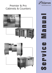
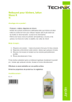
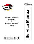
ISO 14001
Service Manual
EPrem Cabinets &
Counters
with
Prem Controller
ISO 9001
Re-Issued Version July 2010
Contents
Environmental Management Policy
Disposal Requirements
Cabinet & Counter Description
Controller Operation
Operating Modes
Fuzzy Logic
Defrost Operation
Alarms & warnings
Service Adjustments
Parameters Cabinets & Counters
Technical Data
Wiring Diagrams
1
1
2
2 to 4
4
5
5 to 6
6 to 7
7 to 8
9 to10
11 to12
13 to 17
Environmental Management Policy for Service Manuals and Duets.
Product Support and Installation Contractors
Foster Refrigerator recognises that its activities, products and services can have an adverse impact upon the
environment.
The organisation is committed to implementing systems and controls to manage, reduce and eliminate its adverse
environmental impacts wherever possible, and has formulated an Environmental Policy outlining our core aims. A
copy of the Environmental Policy is available to all contractors and suppliers upon request.
The organisation is committed to working with suppliers and contractors where their activities have the potential to
impact upon the environment. To achieve the aims stated in the Environmental Policy we require that all suppliers
and contractors operate in compliance with the law and are committed to best practice in environmental
management.
Product Support and Installation contractors are required to:
1. Ensure that wherever possible waste is removed from the client’s site, where arrangements are in place all
waste should be returned to Foster Refrigerator’s premises. In certain circumstances waste may be disposed
of on the clients site; if permission is given, if the client has arrangements in place for the type of waste.
2. If arranging for the disposal of your waste, handle, store and dispose of it in such a way as to prevent its
escape into the environment, harm to human health, and to ensure the compliance with the environmental law.
Guidance is available from the Environment Agency on how to comply with the waste management ‘duty of
care’.
3. The following waste must be stored of separately from other wastes, as they are hazardous to the environment:
refrigerants, polyurethane foam, oils.
4. When arranging for disposal of waste, ensure a waste transfer note or consignment note is completed as
appropriate. Ensure that all waste is correctly described on the waste note and include the appropriate six-digit
code from the European Waste Catalogue. Your waste contractor or Foster can provide further information if
necessary.
5.
Ensure that all waste is removed by a registered waste carrier, a carrier in possession of a waste management
licence, or a carrier holding an appropriate exemption. Ensure the person receiving the waste at its ultimate
destination is in receipt of a waste management licence or valid exemption.
6. Handle and store refrigerants in such a way as to prevent their emission to atmosphere, and ensure they are
disposed of safely and in accordance with environmental law.
7. Make arrangements to ensure all staff who handle refrigerants do so at a level of competence consistent with
the City Guilds 2078 Handling Refrigerants qualification or equivalent qualification.
8.
Ensure all liquid substances are securely stored to prevent leaks and spill, and are not disposed of to storm
drains, foul drain, surface water to soil.
DISPOSAL REQUIREMENTS
If not disposed of properly all refrigerators have components that can be harmful to the environment. All old
refrigerators must be disposed of by appropriately registered and licensed waste contractors, and in accordance
with national laws and regulations.
1
EPrem Cabinet and Counter Description
The EPrem range, so called as can save up to 50% on energy usage, comes in two formats, the Full Gastronorm
and the Non-Gastronorm.
Both come with a choice of capacities and temperatures, the full format comes with 650x530 shelves whereas the
Non-Gastronorm unit has a smaller shelf measuring 530x550.
The units are manufactured as a one piece shell with easy clean stainless steel exterior. Each conforms to the
current legislation and exceeds the Montreal protocol by using zero ODP (ozone depleting substances) refrigerants
and insulation. There is also the added option of having Hydrocarbon refrigerant.
Each unit’s temperature is controlled by a microprocessor with digital temperature display. There are several
temperature options available exceeding the Climate Class 5 operations by giving an ambient temperature to 43°C.
Each temperature display is also easy to read with a wipe clean finish.
The standard form of refrigeration system in this unit is integrated with an air-cooled condensing unit that allows
cooled air to circulate through the evaporator, via the fan into storage areas. It does this by distributing the
refrigerant into the evaporator controlled by a capillary.
Remote systems are also available as an option, the difference being, the evaporator is controlled by an expansion
valve instead of capillary.
Other points to be made on these units are that they have coated coils to prevent corrosion and to help prolong the
refrigerators life. They have easily removable thermal breaks, giving easy access to the door frame heater.
Also all have a wide magnetic gasket that gives a positive door seal.
Cabinets come with an easily removable plug box and lid, while cabinets have an easy access condensing unit
fitted on the side to make servicing that much easier.
Controller Operation
Prem Controller (00-554478)
FEPC controller Display (00-556122)
The controller has two displays, the right hand display gives temperature readout and the left hand will display fault
codes, error codes and other information.
The controller connects to the power switching unit using a ten way and sixteen way ribbon cable.
Temperature Display symbols
Compressor: LED illuminated beneath the symbol indicates the compressor in operation.
Fan/s: LED illuminated beneath the symbol indicates the fan/s in operation.
Defrost: LED illuminated beneath the symbol indicates defrost in operation.
There is a circular reed switch fitted at the bottom of the facia panel that corresponds with a magnet at the top of
the door to stop the evaporator fan when the door is opened (not fitted on heated or fish cabinets).
Door switch kit part number is 16240122.
2
Basic User Functions
Button 1
Button 2
Button 4
Button 3
Set Unit to Standby
Press any button (1, 2, 3 or 4)
Press button 1 (Off)
All relay outputs fall low. Display will show
Set Unit to Run
Press button 4
System will restart
Check Set Point (Low Temperature Band)
Press any button (1, 2, 3 or 4)
Press button 3. (Temp)
Press button 1(-) or 2 (+) to raise or lower the set point.
Press button 4 (<<) to exit to ‘User Main Menu)
View Ancillary Temperatures (If relevant Probes are fitted)
Press any button (1, 2, 3 or 4)
Press button 4 for ‘Service’ menu.
Press button 1 for ‘Info’ menu.
Use buttons 1 (
) and 2 (
) to view temperatures
(Text Air Evaporator Condenser Food Tlo
Thi Text )
Tlo indicates the lowest temperature the machine has achieved.
Thi indicates the highest temperature the machine has achieved.
This information is useful when checking on the possible cause
of iced up evaporators.
(If the relevant probe is not fitted display shows ---)
Press button 4 (<<) to exit to ‘User Main Menu)
Basic ‘User’ Adjustments
Increase Set Point. (High Point of Temperature Band)
Press any button (1, 2, 3 or 4)
Press button 3 for ‘Temp. Set’ menu.
Use button 2 (+) to adjust setting to required value.
Press button 3 (OK) to save and exit.
Press button 4 (<<) to exit without saving.
Display will return to ‘User Main Menu’.
Note: Maximum value is dependant upon Maximum Temperature Set-Point
parameter setting.
3
Decrease Set Point. (Low Point of Temperature Band).
Press any button (1, 2, 3 or 4)
Press button 3 for ‘Temp. Set’ menu.
Use button 1 (-) to adjust setting to required value.
Press button 3 (OK) to save and exit.
Press button 4 (<<) to exit without saving.
Display will return to ‘User Main Menu’
Note: Minimum value is dependant upon Minimum Temperature Set-Point
parameter setting.
Initiate Manual Defrost
Press any button (1, 2, 3 or 4)
Press button 2 for ‘Defrost’ initiation.
A defrost and Recovery Program will occur.
On completion unit will return to normal operation.
Energy
Note: Not available on Heated (Xt.) variants
Change Display Text Language
Press any button (1, 2, 3 or 4)
Press button 4 for ‘Service’ menu.
Press button 1 for ‘Info’ menu.
Press button 3 for ‘Text’ menu.
Use buttons 1 (-) and 2 (+) to select language.
Press button 3 (OK) to save and exit.
Press button 4 (<<) to exit without saving
Display will return to ‘User Main Menu’
Operating Modes
Normal Operation
When mains power is initially applied the LCM text display will show the start up message: (including the software
version and the base model operating range), for a period of three seconds, during which time the controller
performs a ‘self check’. The LED temperature display will not illuminate during this time. After 3 seconds the text
will then extinguish and the LED display will show the temperature measured by Probe 1 (T1) - the internal air
temperature probe. The function LED’s will also illuminate to show which output relays are energised. Therefore, if
the measured temperature is not within the pre-set temperature range the controller will activate the condensing or
heating system. All timings (i.e. defrost intervals) will be taken from power up.
The evaporator coil temperature, measured by Probe 2 (T2) may be temporarily viewed by entering the ‘Supervisor
Main Menu’ and pressing button1 (Info); (this facility is only available if the evaporator probe is selected by virtue of
model or as an addition in the parameters). The Condenser Coil and Food Probe temperature may also be viewed
from this menu if they are fitted by scrolling through the menu using button 1 ( ) and 2 ( ). If no buttons are
pressed for a period of one (1) minute the ICM display will be extinguished.
Electrical Isolation
If mains power is removed from the controller with the unit operational, the entire system will cease and the relay
outputs will fall low, the LCM and LED displays will be extinguished. When mains power is re-established the
controller will carry out the initial self-test routine and then the system will re-start and carry on in the ‘Normal
Operating Mode’. However, if the controller is set to ‘Stand-by’ mode when the mains fails or is removed, on reconnection the controller will return to the ‘Stand-by’ mode.
4
Fuzzy Logic
These are settings that maintain the temperature of the cabinet in a more energy efficient manner.
It works by controlling the evaporator fan/s, defrost and temperature in high usage times by transferring the
operation to a second set of control parameters.
When the cabinet is first switched On the economy settings control the operation of the temperature and will remain
at those settings until the controller, by monitoring the door opening frequency and the air and evaporator
temperatures, identifies a higher usage and switches over to the ‘2 SET MODE’ (2nd parameter set management).
When the machine is used at a lower level the economy settings are activated the cabinet temperature is allowed
to rise to the setting ‘TEMP SET 1’ setpoint 1. This is set to a higher temperature setting to allow the air
temperature to rise without having much of an impact on the product temperature.
In addition the fan/s will modulate as set in ‘FAN RUN TM’ evaporator fan on and off as set in ‘FAN OFF TM’.
With the fans controller in this way they will generate less heat into the cabinet therefore reduce the requirement of
the condensing system.
Fan Operation.
The evaporator fan/s will run normally when the compressor is running but will commence cycling off and on as
determined in parameter ‘FAN OFF TM’ fan off and fan run ‘FAN RUN TM’.
The fans will run without the compressor during timed off cycle defrost but will not run during hot gas or electric
defrost.
For models that don’t have door switches fitted, i.e. counters, the fuzzy logic will not function as the controller is
unable to monitor door opening factors.
NOTE:
The ECM evaporator fan motor has a low heat output motor and it should be noted that when the power is switched
off stops rotating straight away.
Auto Defrost operation.
The defrost frequency is determined by the usage of the machine.
In the economy mode it may not perform a defrost as by monitoring the air temperature, evaporator temperature
and door opening factor it may decide that there is insufficient ice build up on the evaporator so defrosting is not
required.
The parameter ‘DFR/24H’ defrost frequency / 24 H determines how many defrost in a 24 hour period. The cabinet
will perform at least 1 defrost per day and if the setting is 3 it has the potential to initiate up to 2 additional defrost
whilst in the economy mode.
Should the cabinet experience constant usage the controller will switch automatically to the second parameter
settings which could under circumstances of heavy usage initiate up to the amount defrosts per day as set in
parameter ‘DEF 24/H 2’.
The second parameter settings ‘2 Set Mode’ will now be active,
It is important to note that during the first few days of operation the defrosting frequency may be at regular intervals
but these will reduce as the controller monitors the operation.
NOTE: for cabinets and counters without door switches the amount of defrosts per day will be as set in the
parameters ‘Defrost/Day1’ and ‘Defrost/Day2’.
The defrost operation is displayed as follows:
Defrost Initiated
The LED temperature display is extinguished, although the function indicators will remain illuminated (dependant
upon the type of defrost). The LCM text display will show ‘Defrost On’ and the time elapsed clock will start. The
defrost will continue until either the Defrost termination temperature or time is reached, at which time the defrost
relay will be de-energised. The drain down time will commence during which no relays will be energised, the drain
down time is determined by parameter ‘Drain Time’, allowing for the melt water to drain from the evaporator. On
completion the condensing unit will start but the evaporator fan/s will not, this is the ‘Fan Delay Period’
Fan Delay
This period is to allow the evaporator to cool before the evaporator fans restart (this does not apply to ‘Off Cycle’
defrost type. This prevents any warm air remaining from the defrost being distributed throughout the product.
During the fan delay period (determined by the parameter ‘FAN DLY TP’ ) the LED temperature display remains
extinguished, although the condenser function will be illuminated. The ICM text display will show ‘Defrost On’ and
the time elapsed clock will continue. The fan delay period will continue until the temperature, determined by the fan
delay temperature parameter ‘FAN DLY TP’, has been achieved. The evaporator fans will restart and the unit will
enter the recovery period.
5
Temperature Recovery Period
This period allows the unit to cool the load back to the normal operating temperature range following defrost. The
internal air temperature may have risen out of the normal temperature ranges during the defrost period due to the
doors being opened for loading/unloading or a slight transfer of warm air from the evaporator to the air temperature
probe. During the temperature recovery period, which is a fixed 5 minute period after the evaporator fans restart,
the LCM text display will change to show ‘Temp. Recovery’ with the time elapsed clock continuing. During the first
two minutes of the temperature recovery period the LED temperature display will only show the function indicators,
however for the final three minutes of the temperature recovery period the internal air temperature will also be
shown.
Normal Operating Mode
Five minutes after the evaporator fans have restarted the LCM text display will be extinguished and the unit will
enter the normal operating mode and defrost will be completed.
A defrost can be initiated manually if required. The procedure for this is detailed in the ‘User Functions’ section, but
the defrost operation and display will be the same as for an automatic defrost. Should a manual defrost be initiated
the automatic defrost clock will be reset, and therefore subsequent defrosts will follow at the normal time interval.
Alarms and Warnings
Door Opening Warning
Display shows door open warning. The controller siren sounds, but can be muted by pressing any button. The
display will continue until cancelled by shutting the door. If the door open warning is muted and the door is left open
the warning will eventually become a temperature related problem and then the appropriated alarm would be
generated. The door alarm will sound after the period determined from the ‘Door Stop’ plus the ‘Door Alarm’
parameters. This will occur if the ‘Door Switch’ parameter is set to ‘Yes’
High Temperature Alarm
This alarm occurs if the internal temperature rises above the set point plus the hysteresis value, plus the high alarm
temperature differential for the time determined by the alarm delay period. If this alarm occurs, the LCM display will
flash the above alarm message. The alarm siren will sound but can be muted for a period of one hour by pressing
any button. The LCM display will continue to flash throughout this alarm. The LED display will show the internal air
temperature and the function icons. If the temperature has not returned to within the operating limits after one hour
the alarm will resound for one minute. This process will continue until automatically cancelled by the system
returning to its normal operating temperatures.
Low Temperature Alarm
This alarm occurs if the internal temperature falls below the set point minus the low alarm temperature differential
for the time determined by the alarm delay period. If this alarm occurs, the LCM display will flash the above alarm
message. The alarm siren will sound but can be muted for a period of one hour by pressing any button. The LCM
display will continue to flash throughout this alarm. The LED display will show the internal air temperature and the
function icons. If the temperature has not returned to within the operating limits after one hour the alarm will
resound for one minute. This process will continue until automatically cancelled by the system returning to its
normal operating temperatures.
Air Temperature Probe Failure
The display will flash ‘Probe 1’, as shown above, indicating an air probe (T1) failure; it is not possible to display the
temperature with a probe 1 fault. The alarm will sound but can be temporarily muted by pressing any button. The
siren will resound after one hour for one minute if the fault has not been rectified. During this period the unit will
continue to operate, as determined by the ‘Comp. Cycle’ parameter, but will have a reduced performance as the
compressor ON and OFF function will be on a timed basis. It is not possible to view the air or food temperature
when this fault occurs. The alarm message will continue to be displayed until the fault has been rectified and then
cleared by entering the ‘Basic User Functions’ and deleting the alarm message.
Evaporator Temperature Probe Failure
The display will flash ‘Probe 2’, as shown above, indicating an evaporator probe (T2) failure. The alarm will sound
but can be temporarily muted by pressing any button. The siren will resound after one hour for one minute if the
fault has not been rectified. During this period the unit will continue to operate but this failure will have an effect on
the defrost, termination on a timed basis and not temperature, and therefore effect efficiency if unfixed, The alarm
message will continue to be displayed until the fault has been rectified and will then automatically reset and the unit
will function normally
6
Note.
The condenser probe is no longer fitted as in previous model.
The ‘Condenser Clean’ and ‘Service Due’ warnings will not be displayed as the parameters are set to ‘0’ and
therefore switched off.
The diagnostics is no longer incorporated as in previous models so functions SF010, SF020 and SF030 will not be
displayed.
Service Adjustments
The controller has three ‘Service’ modes – the Output Relay Test function, the Model Selection Function and the
individual Parameter adjustments. These features are accessible only from the ‘Service Main Menu’.
Service Main Menu.
Press any button (1, 2, 3 or 4)
Press button 4 ‘Service’ for the ‘Service Menu’.
Press button 3 ‘Settings’ for the ‘Settings Menu’.
Press button 2 ‘+’ to advance the code number to ‘131’ if you go beyond the
number press button 1 ‘-‘ to lower to the correct number.
Press button 3 ‘OK’ to enter the ‘Service Main Menu’.
To exit the ‘Service Main Menu’ and return to the ‘User Main Menu’ press button 4
‘<<’. If no further buttons are pressed for one minute the controller will revert to the
normal operating mode.
Out-Put Relay Test
Whilst in the ‘Service Main Menu’ press button 1 ‘Test’ all
relays will de-energise and the screen opposite will be
displayed.
To test relay 1 ‘Condensing Unit Relay’ press button 1.
Relay 1 will energise.
To test relay 2 ‘Evaporator Fan Relay’ press button 2.
Relay 2 will energise.
To test relay 3 ‘Defrost System Relay’ press button 3.
Relay 3 will energise.
To test all three relay outputs press buttons 1, 2 and 3
together. All three relays will energise.
To exit the ‘Output Relay Test Menu’ and return to the ‘User Main Menu’ press button 4 ‘<<’. If no further buttons
are pressed for one minute the controller will revert to the normal operating mode.
Model Selection Function
The ‘Model Selection Function’ allows the controller to be set during manufacturing, or replacement, to the most
appropriate model range with the accompanying default setting values. There are eleven temperature default
models which are:- HIGH TEMP-D (High Temperature with Door Switch), HIGH TEMP (High Temperature without
Door Switch), LOW TEMP-GD (Low Temperature with Hot Gas Defrost and Door Switch), LOW TEMP-G (Low
Temperature with Hot Gas Defrost without Door Switch), LOW TEMP-ED (Low Temperature with Electric Defrost
and Door Switch), LOW TEMP-E (Low Temperature with Electric Defrost without Door Switch), MEAT TEMP-GD
(Meat Temperature with Hot Gas Defrost and Door Switch), MEAT TEMP-G (Meat Temperature with Hot Gas
Defrost without Door Switch), FISH TEMP. (Fish Temperature without door switch), WINE TEMP. (Wine
Temperature with door switch), HEATED CAB. (Heated Temperature without door switch).
All controllers arrive from the manufacturer with the HIGH TEMP-D settings if any other setting is required the
following procedure should be followed.
7
From ‘Service Main Menu’ depress button 2 ‘Model’
Use button 1(-) or button 2(+) to select required model
(in this case wine)
Once the model has been selected depress button 3 (OK) to confirm.
Once confirmed the controller will reset parameter values and return to the ‘Service Main Menu’.
If during the model selection button 4(<<) is pressed, the controller will revert to the ‘Service Main Menu’ without
making any changes. Similarly if no buttons are pressed for a period of one minute the controller will revert to the
‘Normal Operating Mode’ without saving any of the changes.
NOTE: When the model change mode is entered any previously made changes to the parameters will be lost and
will revert to the default parameters.
Parameter Adjustment
The individual Parameter Adjustment allows the controller’s standard settings to be adjusted to suit particular
requirements. This allows adjustment for specific customer, engineer requirement or to overcome an operating
problem.
If any parameters require adjusting; for example if the standard number of defrosts in the economy or heavy duty
settings (2) requires to be increased the following procedure should be followed.
From ‘Service Main Menu’ depress button 2 ‘Model’
Use button 2 ( ) to scroll through to the required parameter heading.
If the require parameter is missed use button 1( ) to scroll backwards through
the parameters.
Defrost/Day 1
Select ‘Defrost/ Day 1’ for the economy settings defrost or ‘Defrost/Day 2’ for the
heavy duty settings.
Defrost/Day 2
Depress button 3 (Set) to enable adjustment of the parameter value.
Use button 1 (-) or 2 (+) to adjust the value to the required setting.
In this case 6.
Defrost/Day 2
4
Defrost/Day 2
6
Depress button 3 (OK) to save the new value. Controller updates settings and the
display shows the next parameter heading
If no further changes are required press button 4 to return to the ‘Service Main
Menu’.
If during the model selection button 4(<<) is pressed, the controller will revert to the ‘Service Main Menu’ without
making any changes. Similarly if no buttons are pressed for a period of one minute the controller will revert to the
‘Normal Operating Mode’ without saving any of the changes.
8
EPrem Controller Default Parameter Values
Title
Parameter Definitions
Scale
Readout scale
Min Temp 1
Minimum setpoint [ I ]
Max Temp 1
Maximum setpoint [ I ]
Temp. Set 1
Setpoint [ I ]
Temp. Hyst 1
Thermostat hysteresis [ I ]
Compr. Rest
Default
Dim
High
TO
High
T-ND
Low
TG
Low
TG-ND
Low
TE
Low
TE-ND
Meat
TG
Meat
TG-ND
Fish
Wine
Heated
ºC
flag
ºC
ºC
ºC
ºC
ºC
ºC
ºC
ºC
ºC
ºC
ºC
Max
Temp 1
1
ºC
1
1
-21
-21
-21
-21
-2
-2
-1
8
83
Min
MAX
ºC ; ºF
-40
Min
Temp 1
Min
Temp 1
100
3
ºC
3
3
-19
-19
-19
-19
0
0
1
12
91
Max
Temp 1
2
ºC
2
2
-19
-19
-19
-19
-1
-1
0
10
87
-10
10
3
ºC
3
3
3
3
3
3
2
2
2
2
-3
Minimum compressor rest time
0
30
2
min
2
2
2
2
2
2
2
2
2
2
0
Comp. ON
Compressor run with T1 failure
0
30
7
min
7
7
7
7
7
7
7
7
7
7
7
Comp. OFF
Compressor stop with T1 failure
0
30
3
min
3
3
3
3
3
3
3
3
3
3
3
Defrost/Day 1
Defrost frequency / 24h
0
24
2
1/24h
2
2
4
4
4
4
4
4
0
4
0
Defr. End Tp
Defrost end temperature
-40
40
20
ºC
20
20
20
20
20
20
20
20
20
20
20
Defr. End Tm
Maximum defrost duration
1
120
20
min
20
20
20
20
20
20
20
20
20
20
20
Defr. Type
Defrost type
OFF
flag
OFF
OFF
GAS
GAS
ELE
ELE
GAS
GAS
OFF
OFF
OFF
Drain Time
Drain down time
0
30
2
min
2
2
2
2
2
2
2
2
2
2
2
Def. Display
Defrost display control
0
60
10
min
10
10
10
10
10
10
10
10
10
10
10
Fan in Def
Fan activity during defrost
No
Yes
Yes
flag
Yes
Yes
No
No
No
No
No
No
Yes
Yes
Yes
Fan Dly. Tp
Fan re-start delay temperature
-40
40
0
ºC
0
0
0
0
0
0
0
0
0
0
0
Fan Dly. Tm
Evaporator fan maximum time-out
0
120
3
min
3
3
3
3
3
3
3
3
3
3
3
Fan Tm Con
Evaporator fan timed control
No
Yes
Yes
flag
Yes
Yes
Yes
Yes
Yes
Yes
Yes
Yes
No
Yes
No
Fan Stop Dly
Fan stop delay
0
180
15
sec.
15
15
15
15
15
15
15
15
15
15
15
Fan Off Tm
Timed fan stop
0
30
2
min
2
2
3
3
3
3
3
3
2
2
2
Fan Run Tm
Timed fan run
0
30
1
min
1
1
1
1
1
1
1
1
1
1
1
Lo Alarm dt
Low alarm differential
-12
0
-5
ºC
-5
-5
-5
-5
-5
-5
-5
-5
-5
-5
-5
Hi Alarm dt
High alarm differential
0
12
5
ºC
5
5
5
5
5
5
5
5
5
5
5
Alarm Delay
Alarm temperature delay
0
120
90
min
90
90
90
90
90
90
90
90
90
90
90
OFF/ ELE/ GAS
9
Con Alrm Tp
Condenser alarm temperature
0
Con Hi Op
Condenser high temp. alarm
operation
Con Clear
Condenser cleaning period
0
Service Due
Service due interval
Eco Sense
Sensitivity function eco / heavy duty
2 Set Mode
2nd parameter set switching mode
Min.Temp. 2
Minimum 2nd temp. set
-40
Max. Temp. 2
Maximum 2nd temp. set
Temp. Set 2
Effective 2nd temperature set point
Temp. Hyst 2
75
60
ºC
60
60
60
60
60
60
60
60
60
60
60
NON
flag
NON
NON
NON
NON
NON
NON
NON
NON
NON
NON
NON
52
0
wks
0
0
0
0
0
0
0
0
0
0
0
0
200
0
wks
0
0
0
0
0
0
0
0
0
0
0
1
5
3
flag
3
3
3
3
3
3
3
3
3
3
3
HDD
flag
HDD
HDD
HDD
HDD
HDD
HDD
HDD
NON
NON
NON
11SH
1
ºC
1
1
-21
-21
-21
-21
-2
-2
1
1
1
11SL
100
3
ºC
3
3
-21
-21
-21
-21
0
0
3
3
3
11SL
11SH
1
ºC
1
1
-21
-21
-21
-21
-2
-2
1
1
1
Hysteresis 2nd temperature set
-10
10
3
ºC
3
3
3
3
3
3
2
2
3
3
3
Fan Tm Con 2
Evap. fan timed control in mode 2
NO
YES
NO
flag
NO
NO
NO
NO
NO
NO
NO
NO
NO
NO
NO
Defrost/Day 2
Defrost Frequency / 24h in mode 2
0
24
4
1/24h
4
4
4
4
4
4
4
4
4
4
4
Door Switch
Door switch enabling
NO
YES
YES
flag
YES
NO
YES
NO
YES
NO
YES
NO
YES
YES
YES
Door Stop
Compressor stop delay from door
opening
0
30
1
min
1
1
1
1
1
1
1
1
1
1
1
Door Alarm
Door alarm delay
0
30
8
min
8
8
8
8
8
8
8
8
8
8
8
Air o/s
T1 (air) probe offset
-12
12
0
ºC
0
0
0
0
0
0
0
0
0
0
0
Evap. Probe
T2 (evap.) probe enabling
NO
YES
NO
flag
NO
NO
YES
YES
YES
YES
YES
YES
NO
NO
NO
Evap. o/s
T2 (evap.) probe offset
-12
12
0
ºC
0
0
0
0
0
0
0
0
0
0
0
Cond. Probe
T3 (cond.) probe enabling
NO
YES
NO
flag
NO
NO
NO
NO
NO
NO
NO
NO
NO
NO
NO
Cond. o/s
T3 (cond.) probe offset
-12
12
0
ºC
0
0
0
0
0
0
0
0
0
0
0
Food Probe
T4 (Food) probe enabling
NO
YES
NO
flag
NO
NO
NO
NO
NO
NO
NO
NO
NO
NO
NO
Food o/s
T4 Food) probe offset
-12
12
0
ºC
0
0
0
0
0
0
0
0
0
0
0
Temp Dly
Delay for min./max. temp storage
1
30
5
min
5
5
5
5
5
5
5
5
5
5
5
Food Sim
Thermal Mass Simulation
0
100
3
exp
3
3
3
3
3
3
3
3
3
3
3
Disp. Contr.
LCD Display contrast
0
250
200
flag
200
200
200
200
200
200
200
200
200
200
200
Address
Unit peripheral address
1
255
1
Exp
1
1
1
1
1
1
1
1
1
1
1
NON; ALR; STP
NON; HDD
10
HDD
Technical Data EPrem Cabinets
Model
Gas
Gas Charge
Compressor
Capillary
Defrost Type
Voltage
EPREM S 400H
EPREM S 400L
EPREM G 500H
EPREM G 500L
EPREM G 600H
EPREM G 600M
EPREM G 600L
EPREM G 1100H
EPREM G 1100L
EPREM G 1350H
EPREM G 1350M
EPREM G 1350L
EPREM G 300/300 HL
R134A
R404A
R134A
R404A
R134A
R134A
R404A
R134A
R404A
R134A
R134A
R404A
R134A
R404A
R134A
R404A
R134A
R134A
380 grms
360 grms
380 grms
360 grms
380 grms
380 grms
360 grms
450 grms
660 grms
450 grms
450 grms
660 grms
320 grms
300 grms
380 grms
360 grms
270 grms
360 grms
FR7.5GX
SC15CL
FR7.5GX
SC15CL
FR7.5GX
FR7.5GX
SC15CL
SC15GX
CAJ2446Z-SE
SC15GX
SC15GX
CAJ2446Z-SE
FR7.5GX
SC15CL
FR7.5GX
SC15CL
FR7.5GX
SC12GX
2.8m x 0.042
3.0m x 0.047
2.8m x 0.042
3.0m x 0.047
2.8m x 0.042
2.8m x 0.042
3.0m x 0.047
3.0m x 0.054
3.0m x 0.054
3.0m x 0.054
3.0m x 0.054
3.0m x 0.054
3.0m x 0.042
3.0m x 0.042
2.8m x 0.042
3.0m x 0.047
3.0m x 0.054
2.5m x 0.054
Timed Off Cycle
Hot Gas
Timed Off Cycle
Hot Gas
Timed Off Cycle
Hot Gas
Hot Gas
Timed Off Cycle
Hot Gas
Timed Off Cycle
Hot Gas
Hot Gas
Timed Off Cycle
Electric
Timed Off Cycle
Hot Gas
Timed Off Cycle
Timed Off Cycle
230/50/1
230/50/1
230/50/1
230/50/1
230/50/1
230/50/1
230/50/1
230/50/1
230/50/1
230/50/1
230/50/1
230/50/1
230/50/1
230/50/1
230/50/1
230/50/1
230/50/1
230/50/1
EPREM B 600H
EPREM B 600L
PREM G 600F
PREM G 1350F
Power
Consumption
kW/48hrs
4.2 (indicative)
6.2 (indicative)
4.1 (indicative)
6.2 (indicative)
3.71(tested)
5.4 (indicative)
14.81(tested)
7.6 (indicative)
9.0 (indicative)
6.52 (tested)
10 (indicative)
28.76 (tested)
10.2 (indicative)
3.71(tested)
14.81(tested)
4.8 (indicative)
13.16 (indicative)
Fuse
Rating
13 Amp
13 Amp
13 Amp
13 Amp
13 Amp
13 Amp
13 Amp
13 Amp
13 Amp
13 Amp
13 Amp
13 Amp
13 Amp
13 Amp
13 Amp
13 Amp
13 Amp
13 Amp
Technical Data EPrem Counters
Model
EPREM 1/2H
EPREM 1/2M
EPREM 1/2L
EPREM 1/3H
EPREM 1/3M
EPREM 1/3L
EPREM 1/4H
EPREM 1/4M
EPREM 1/4L
EPREM 2/2H
EPREM 2/2L
EPREM 2/3H
EPREM 2/3L
Gas
Gas Charge
Compressor
R134A
R134A
R404A
R134A
R134A
R404A
R134A
R134A
R404A
R134A
R404A
R134A
R404A
360 grms
360 grms
335 grms
315 grms
315 grms
360 grms
370 grms
370 grms
375 grms
365 grms
360 grms
380 grms
380 grms
FR7.5GX
FR7.5GX
SC 15CL
FR7.5GX
FR7.5GX
SC 15CL
SC12GX
SC12GX
SC 21CLX
FR7.5GX
SC 15CL
SC12GX
SC 21CLX
Capillary
3.0m
3.0m
3.0m
3.0m
3.0m
3.0m
3.0m
3.0m
3.0m
3.0m
3.0m
3.0m
3.0m
X 0.042
X 0.042
X 0.042
X 0.042
X 0.042
X 0.042
X 0.054
X 0.054
X 0.054
X 0.042
X 0.042
X 0.054
X 0.054
Defrost Type
Voltage
Power
Consumption
kW/48hrs
Fuse
Rating
Timed Off Cycle
Hot Gas
Hot Gas
Timed Off Cycle
Hot Gas
Hot Gas
Timed Off Cycle
Hot Gas
Hot Gas
Timed Off Cycle
Hot Gas
Timed Off Cycle
Hot Gas
230/50/1
230/50/1
230/50/1
230/50/1
230/50/1
230/50/1
230/50/1
230/50/1
230/50/1
230/50/1
230/50/1
230/50/1
230/50/1
3.3 (tested)
3.3 (indicative)
6.4 (indicative)
4.7 (indicative)
4.7 (indicative)
23.9 (indicative)
5.2 (indicative)
5.2 (indicative)
23.9 (indicative)
3.8 (indicative)
23.9 (indicative)
11.0 (indicative)
16.8 (indicative)
13 Amp
13 Amp
13 Amp
13 Amp
13 Amp
13 Amp
13 Amp
13 Amp
13 Amp
13 Amp
13 Amp
13 Amp
13 Amp
Note: The Power Consumption values referred to as tested are to the ECA test standard. Actual power consumption will be greatly affected by ambient temperature,
loading, usage and cabinet maintenance.
11
Technical Data EPrem Cabinets using R290 Refrigerant
Model
EPREM S 400H
EPREM S 400L
EPREM G 500H
EPREM G 500L
EPREM G 600H
EPREM G 600M
EPREM G 600L
EPREM G 1100H
EPREM G 1100L
EPREM G 1350H
EPREM G 1350M
EPREM G 1350L
EPREM B 600H
EPREM B 600L
PREM G 600F
PREM G 1350F
Gas
Gas Charge
Compressor
R290
R290
R290
R290
R290
R290
R290
R290
R290
R290
R290
R290
R290
R290
R290
R290
150 grms
150 grms
150 grms
150 grms
150 grms
150 grms
150 grms
200 grms
220 grms
150 grms
150 grms
220 grms
150 grms
150 grms
150 grms
140 grms
TL5CNX
SC15CNX
TL5CNX
SC15CNX
TL5CNX
TL5CNX
SC15CNX
SC12CNX
MX23FB
SC12CNX
SC12CNX
MX23FB
TL5CNX
SC15CNX
SC15CNX
SC12CNX
Capillary
Defrost Type
Voltage
Power
Consumption
kW/48hrs
Fuse
Rating
2.8m
3.0m
2.8m
3.0m
2.8m
2.8m
3.0m
3.0m
3.0m
3.0m
3.0m
3.0m
2.8m
3.0m
3.0m
2.5m
Timed Off Cycle
Hot Gas
Timed Off Cycle
Hot Gas
Timed Off Cycle
Hot Gas
Hot Gas
Timed Off Cycle
Hot Gas
Timed Off Cycle
Hot Gas
Hot Gas
Timed Off Cycle
Hot Gas
Timed Off Cycle
Timed Off Cycle
230/1/50
230/50/1
230/50/1
230/50/1
230/50/1
230/50/1
230/50/1
230/50/1
230/50/1
230/50/1
230/50/1
230/50/1
230/50/1
230/50/1
230/50/1
230/50/1
4.2 (indicative)
6.2 (indicative)
3.8 (indicative)
13.4 (indicative)
3.8 (tested)
5.4 (indicative)
13.4 (tested)
7.6 (indicative)
9.0 (indicative)
5.66 (tested)
9.0 (indicative)
25.1 (tested)
3.8 (tested)
13.4 (tested)
4.8 (indicative)
13.16 (indicative)
13 Amp
13 Amp
13 Amp
13 Amp
13 Amp
13 Amp
13 Amp
13 Amp
13 Amp
13 Amp
13 Amp
13 Amp
13 Amp
13 Amp
13 Amp
13 Amp
Defrost Type
Voltage
Power
Consumption
kW/48hrs
Fuse
Rating
Timed Off Cycle
Hot Gas
Hot Gas
Timed Off Cycle
Hot Gas
Hot Gas
Timed Off Cycle
Hot Gas
Timed Off Cycle
Hot Gas
Timed Off Cycle
230/50/1
230/50/1
230/50/1
230/50/1
230/50/1
230/50/1
230/50/1
230/50/1
230/50/1
230/50/1
230/50/1
3.2 (tested)
3.2 (indicative)
6.4 (indicative)
4.3 (indicative)
4.7 (indicative)
22.8 (indicative)
5.2 (indicative)
5.2 (indicative)
3.8 (indicative)
22.8 (indicative)
11.0 (indicative)
13 Amp
13 Amp
13 Amp
13 Amp
13 Amp
13 Amp
13 Amp
13 Amp
13 Amp
13 Amp
13 Amp
x 0.042
x 0.042
x 0.042
x 0.042
x 0.042
x 0.042
x 0.047
x 0.054
x 0.054
x 0.054
x 0.054
x 0.054
x 0.042
x 0.042
x 0.042
x 0.054
Technical Data EPrem Counters using R290 Refrigerant
Model
EPREM 1/2H
EPREM 1/2M
EPREM 1/2L
EPREM 1/3H
EPREM 1/3M
EPREM 1/3L
EPREM 1/4H
EPREM 1/4M
EPREM 2/2H
EPREM 2/2L
EPREM 2/3H
Gas
Gas Charge
Compressor
R290
R290
R290
R290
R290
R290
R290
R290
R290
R290
R290
150 grms
150 grms
150 grms
150 grms
150 grms
150 grms
150 grms
150 grms
150 grms
150 grms
150 grms
TL5CNX
TL5CNX
SC15CNX
TL5CNX
TL5CNX
SC15CNX
SC12CNX
SC12CNX
TL5CNX
SC15CNX
SC12CNX
Capillary
3.0m
3.0m
3.0m
3.0m
3.0m
3.0m
3.0m
3.0m
3.0m
3.0m
3.0m
X 0.042
X 0.042
X 0.042
X 0.042
X 0.042
X 0.042
X 0.054
X 0.054
X 0.042
X 0.042
X 0.054
Note: The Power Consumption values referred to as tested are to the ECA test standard. Actual power consumption will be greatly affected by ambient temperature,
loading, usage and cabinet maintenance.
12
Wiring Diagrams
13
14
15
16
17
Foster European Operations
France
Foster Refrigerator France SA
Tel: (33) 01 34 30 22 22. Fax: (33) 01 30 37 68 74.
Email: [email protected]
Germany
Foster Refrigerator Gmbh,
Tel: (49) 781 990 7840. Fax (49) 781 990 7844.
Email: [email protected]
Foster Refrigerator
Oldmedow Road
Kings Lynn
Norfolk
PE30 4JU
Tel: 0843 216 8833
Fax: 0843 216 4707
Website: www.fosterrefrigerator.co.uk
Email: [email protected]
a Division of ‘ITW (UK) Ltd’
EPREM CAB/COUNT PREM/SM 07/10
18