1
Operator's/Installation/Service Manual
Braun
Commercial
RA300 Transit Ramp
for
Low-Floor Transit Vehicles
WARNING
Man
International Corporate Hdqrs: P.O. Box 310 Winamac, IN 46996 USA
1-800-THE LIFT ®
(574) 946-6153
FAX: (574) 946-4670
33778
March 2007
l
Read manual
before operating,
installing or
servicing ramp.
Failure to do so
may result in
serious bodily
injury and/or
property damage.
Braun RA300 Transit Ramp
"Providing Access to the World"
®
®
ua
Congratulations
We at The Braun Corporation wish to express our fullest appreciation
on your new purchase.
With you in mind, our skilled craftsmen have designed and assembled
the finest ramp available.
This manual includes operating instructions, installation instructions,
servicing instructions and instructions for troubleshooting, if needed.
Braun ramps are built for dependability and will provide years of service
and mobility independence, as long as the ramp is installed and maintained as
specified, and the ramp is operated by an instructed person.
Sincerely,
THE BRAUN CORPORATION
Ralph W. Braun
Chief Executive Officer
CONTENTS
Ramp Terminology
Maintenance and Lubrication
Ramp Terminology Illustration .................................... 2
Lubrication Diagram ................................................... 20
Ramp Components Terminology Illustration ............. 3
Maintenance and Lubrication Schedule .............. 21-23
Introduction.................................................................... 4
Terminology................................................................ 4
Systems Descriptions
Direction ..................................................................... 4
Ramp Components........................................................ 5
Electrical .................................................................. 24, 25
Ramp Actions and Functions....................................... 5
Hydraulics................................................................ 26, 27
Ramp Operation
Ramp Operation Safety
Troubleshooting
Troubleshooting Diagnosis Chart ........................ 28-30
Safety Symbols ......................................................... 6
Electrical Schematic - BF3248Y & BF3748Y .............. 32
Ramp Operation Safety Precautions ..................... 6, 7
Wiring Diagram - BF3248Y & BF3748Y ...................... 33
Pre-Operation Notes and Details
Ramp Access Doors and Interlocks .......................... 8
Electrical Schematic - BF3248YP ............................... 34
Wiring Diagram - BF3248YP ....................................... 35
Operation Procedured Review .................................. 9
Preventive Maintenance ............................................ 9
Hydraulics
Ramp Operation
Ramp Power Operation............................................ 10
Hydraulic Schematic - BF3248Y & BF3748Y.............. 36
Ramp Manual Operation ...........................................11
Hydraulic Diagram and Parts List - BF3248Y &
Ramp Passenger Safety .....................................11, 12
BF3748Y ....................................................................... 37
Hydraulic Schematic - BF3248YP............................... 38
Ramp Installation
Installation/Service Safety
Hydraulic Diagram and Parts List - BF3248YP ......... 39
Repair Parts
Safety Symbols ....................................................... 13
Ramp Operation Safety Precautions ................. 13, 14
Installation Instructions
Installation Requirements......................................... 14
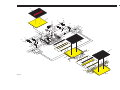
RA300 Ramp Exploded View
Repair Parts List ....................................................... 40
Exploded View (Fold Out) .............................41A, 42A
Chassis Requirements ............................................. 14
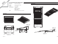
Door Opening........................................................... 15
6SHFLÀFDWLRQVDQG'LPHQVLRQV ....................41B, 42B
Obstructions ............................................................. 15
Installation Illustrations........................................ 15-17
Daily Preventive Maintenance Schedule ................ 43
Electrical Connections.............................................. 18
Electrical Connections Illustration ............................ 19
Page 1
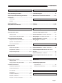
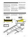
RAMP TERMINOLOGY
Ramp Terminology Illustration
Refer to the illustration below and the illustrations on
SDJHIRULGHQWLÀFDWLRQRIFRPSRQHQWVDQGFODULÀFDtion of direction terminology. Details regarding lift
model variations, terminology, direction and components are provided on pages 4 and 5.
6XEÁRRU
(Fixed)
Drive
Arm
®
Inboard Ramp
(Stage One)
Tension
Cable
Pan Weldment
Drive
Arm
Vertical
Side Plate
(Barrier)
Hand
Hold
IN
LEFT
RIGHT
OUT
As viewed from outside the vehicle
Page 2
Outboard
Ramp
(Stage Two)
RAMP TERMINOLOGY
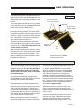
Ramp Components Terminology Illustration
Cable Pulley
Relays
Counter
Cable Tension
Gas Spring
Tension Cable
Cylinder
Remote
Hydraulic Block
(BF3248Y &
BF3748Y Only)
Cam/Hydraulic
Assembly
(BF3248Y &
BF3748Y Only)
Cam/Microswitch
Assembly
Remote Valve Block
(BF3248YP Only)
Pump
Cylinder
Pan Weldment
Ramp Drive Arm
Cable
Pulley
Relays
Cam/Hydraulic
Assembly
(BF3248Y &
BF3748Y Only)
Counter
Ramp Drive Arm
Cable Tension
Gas Spring
Pump
LEFT
Cam/Microswitch
Assembly
IN
Remote Valve Block
(BF3248YP Only)
OUT
RIGHT
As viewed from outside the vehicle
Note: The tension cable, sub
ÁRRUDQGWUDQVLWLRQWKUHVKROG
plate removed from these illustrations for clear view.
Page 3
RAMP TERMINOLOGY
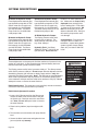
Introduction
Braun RA300 Series Transit
Ramps (to be referred to as
RA300 throughout this manual)
DUHGHVLJQHGIRUXVHLQORZÁRRU
transit vehicles. The RA300
provides vehicle access to people
with disabilities (wheelchair passengers or standees using other
type mobility aids). The commercial oriented ramp is ADA compliant (dependant upon installation
height). See the Installation secWLRQIRU$'$VSHFLÀFDWLRQV
The self-contained “drop-in” unit
requires no remote pump, external hydraulic lines or pre assembly. The hydraulic and electrical
components are internal and easily accessible. A single electrical
feed provides the power supply
(12 volt or 24 volt), the ground, a
ramp OUT signal (+), a ramp IN
signal (+) and various indicator
signals.
The RA300 features a 32” wide
ramp in a 34” wide package. A
´ÁRRUSRFNHWµEXLOWLQWRWKHFKDVVLVÁRRUV\VWHPDOORZVIRUVLPSOH
installation (dimensional requirePHQWVVSHFLÀHGLQWKH,QVWDOODWLRQ
section).
7KH5$LVVSHFLÀFDOO\GHsigned to be operated by an
attendant. The ramp installer
provides an appropriate control
switch for the end user. Consquently, the operating instructions contained in this manual
are generic due to the limitless
variables.
Page 4
The RA300 provides fully automatic operation of ramp functions.
The electric/hydraulic system is
controlled by two relays which activate the hydraulic pump in opposite directions for deploy and stow
functions (powering a dual-acting
hydraulic cylinder). No sensitive
electronic controls or sensors are
required for operation.
All RA300 ramp models feature
gravity down "drift" during the
deploy cycle. When deploying
the ramp, the motor stops running
when the ramp reaches an approximate 45° angle. The ramp
continues to slowly lower the
remaining distance by the force of
gravity.
5DPSPRGHOQXPEHUVZLWKVXIÀ[
"Y" are hydraulic fold with gravity
down "drift" feature when deploying and stowing. When stowing
the ramp and it folds inward beyond the 15° shut off point, gravity
lowers the ramp to the pan.
Ramp model numbers with sufÀ[<3DUHK\GUDXOLFSRZHUHG
throughout the stow cycle (to full
stow). The hydraulic system remains pressurized while the ramp
is in the stowed position.
The pressure relief valves built
into the pump prohibit the ramp
from lifting (raising) with approximately 20 pounds or more on the
ramp.
Instructions are provided for
manual operation of the ramp
in event of power or equipment
failure. See Manual Override
on the following page for further
details.
Read and become familiar with
all operation safety precautions,
pre-operation notes and details,
operating instructions and manual
operating instructions before attempting operation.
Terminology: Become familiar
with the terminology that will be
used throughout this manual.
Become familiar with the idenWLÀFDWLRQRI5$FRPSRQHQWV
and their functions. Contact your
sales representative or call The
Braun Corporation at 1-800-THE
LIFT® if any of this information is
not fully understood.
Direction: The terms “left”,
“right”, “in” and “out” will be used
throughout this manual to indicate
direction (as viewed from the outside of the vehicle looking directly
at the ramp). Refer to the TermiQRORJ\,OOXVWUDWLRQVIRUFODULÀFDWLRQ
of direction terms.
RAMP TERMINOLOGY
Ramp Components
Refer to the Terminology Illustrations on pages 2 and 3.
components from above. The
cover is easily removed for access to drive components. The
VXEÁRRUSURYLGHVDQDQWLVNLG
surface for entry and exit when
the ramp is deployed. The
RA300 stows (folds) onto the sub
ÁRRUSURYLGLQJDQXQREVWUXFWHG
antiskid surface for entry and exit
when the ramp is not in use.
Ramp Assembly: The ramp
assembly is made of an inboard
ramp section (stage one) and an
outboard ramp section (stage
two). Each aluminum ramp section features vertical side plates
and full antiskid surface.
Deploy: Deploy is the action of
the ramp assembly extending and
unfolding to ground level when
the DEPLOY (OUT) switch* is
activated (*installer supplied).
Stow Position: Stow position
is achieved when the two stage
ramp assembly is fully retracted
and folded (resting fully on the
pan weldment).
Stow: Stow is the action of the
ramp assembly raising and folding inward to stow position when
the STOW (IN) switch* is activated (*installer supplied).
Manual Override: Manual
operation is achieved without the
use of any mechanical release or
complicated procedures. Simply
use the Hand Holds provided on
the ramp assembly to manually
deploy or stow the ramp. Minimal physical effort is required to
URXWHWKHK\GUDXOLFÁXLGWKURXJK
the system. Slow steady motion
results in the least resistance and
easy operation. The faster you
attempt to manually operate the
ramp, the greater the resistance.
See Ramp Manual Operation on
page 11 for further details.
Pan Weldment (Housing):
The pan is the stainless steel
(casing) mounted in the vehicle
ÁRRUV\VWHPZKLFKFRQWDLQVWKH
hydraulic pump and electrical
components that power the ramp
electric/hydraulic systems. The
À[HGVXEÁRRUFRYHUSURWHFWVWKH
Drive Arm Assembly:
The cylinder driven three stage
drive arm assembly deploys and
stows the ramp assembly.
Ramp Actions and Functions
Page 5
RAMP OPERATION
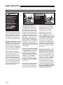
Safety Symbols
SAFETY FIRST!
Know That....
All information contained
in this manual and
supplements (if included), is provided for your safety. Familiarity
with proper operation instructions
as well as proper maintenance
procedures are necessary to ensure safe, trouble free operation.
Safety precautions are provided
to identify potentially hazardous
situations and provide instruction
on how to avoid them.
A
D
B
WARNING
C
This symbol indicates
important safety
information regarding
a potentially hazardous situation that
could result in serious
bodily injury and/or
property damage.
CAUTION
This symbol indicates
important information
regarding how to
avoid a hazardous
situation that could
result in minor personal injury or property
damage.
Note:$GGLWLRQDOLQIRUPDWLRQSURYLGHGWRKHOSFODULI\RUGHWDLODVSHFLÀFVXEMHFW
These symbols will appear throughout this manual. Recognize the seriousness of this information.
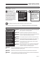
Ramp Operation Safety Precautions
WARNING
If the ramp operating
instructions, manual
operating instructions
and/or ramp operation
safety precautions are
not fully understood,
contact The Braun
Corporation immediately. Failure to do so
may result in serious
bodily injury and/or
property damage.
WARNING
Read manual and supplement(s) before operating ramp.
Read and become familiar with all safety precautions, preoperation notes and details, operating instructions and
manual operating instructions before operating the ramp.
Note: All transit agency personnel (drivers and ramp attendants) must read and become familiar with the contents of this manual and supplement(s) before operation.
WARNING
Load and unload on level surface only.
WARNING
Engage vehicle parking brake before operating ramp.
WARNING
Provide adequate clearance outside the vehicle to accommodate the ramp before opening lift door(s) or operating
ramp.
WARNING
Inspect ramp before operation. Do not operate ramp if you suspect lift damage, wear or
any abnormal condition.
WARNING
Keep operator and bystanders clear of area in which the ramp operates.
WARNING
/RDGDQGXQORDGFOHDURIYHKLFXODUWUDIÀF
WARNING
Open ramp door(s) fully and secure before operating ramp.
WARNING
Do not overload or abuse. The rated capacity is 300 kilograms (660 pounds).
Page 6
RAMP OPERATION
Ramp Operation Safety Precautions (continued)
WARNING
Do not activate control switch(es) when anyone is near the area in which ramp operates.
WARNING
It is the responsibility of the attendant to oversee and assist ramp passengers.
WARNING
The wheelchair passenger and/or attendant must ensure the ramp is fully deployed
before exiting the vehicle.
WARNING
Attendants must never operate the vehicle, the ramp or attend to passengers if intoxicated.
WARNING
Intoxicated passengers should not be allowed to board the vehicle.
WARNING
Wheelchair passengers must position and secure (buckle, engage, fasten, etc.) the
wheelchair-equipped occupant seat belt before loading onto the ramp.
WARNING
Be aware of the ramp slope (angle).
WARNING
Wheelchair passengers should not raise front wheelchair wheels (pull wheelie) when on
the ramp.
WARNING
The wheelchair must be positioned in the center of the ramp when loading and unloading.
WARNING
Keep ramp owner’s manual in ramp-mounted vehicle at all times.
WARNING
0DLQWHQDQFHDQGOXEULFDWLRQSURFHGXUHVPXVWEHSHUIRUPHGDVVSHFLÀHGLQWKLVPDQXDO
E\DXWKRUL]HGFHUWLÀHGVHUYLFHSHUVRQQHO
WARNING
Never modify (alter) a Braun Corporation ramp.
WARNING
Do not use accessory devices not authorized by The Braun Corporation.
WARNING
Do not remove any guards or covers.
WARNING
If the information contained in this manual is not fully understood, contact The Braun
Corporation immediately.
WARNING
)DLOXUHWRIROORZWKHVHVDIHW\SUHFDXWLRQVPD\UHVXOWLQVHULRXVERGLO\LQMXU\DQGRUSURSerty damage.
Page 7
RAMP OPERATION
Pre-Operation Notes and Details
The RA300 Ramp provides
vehicle access to people with
disabilities (wheelchair passengers or standees using other type
mobility aids). The commercial
oriented RA300 Ramp is operated
by the transit vehicle driver/attendant. Unless your transit agency
has a published policy stating that
driver/attendants do not aid ramp
passengers, safe entering and
exiting of ramp passengers is
the responsibility of the driver/
attendant.
As stated in the Ramp Operation
Safety section, all information in
this manual is provided for the
safety of passengers, attendants
and bystanders. Recognize the
seriousness of this information.
Read and become familiar with
all ramp operation safety precautions, pre-operation notes and
details, operating instructions and
manual operating instructions
before attempting ramp operation procedures or assisting ramp
passengers boarding and exiting
the vehicle.
Ramp Access Doors and Interlocks
Attendants must become familiar
with the vehicle ramp access door
system and interlock(s), as well
as the proper operation of the
ramp.
Vehicle ramp access door conÀJXUDWLRQVDQGRSHUDWLRQSURFHdures vary. Ensure the ramp door
is fully open before activating the
ramp (an interlock typically prevents ramp operation unless the
door is fully open). Attendants
and passengers must keep clear
of the area in which the power
door operates. Ensure the path
is clear before closing the door.
Be sure the door is fully closed
before attempting to drive the vehicle (interlocks typically ensure
this).
Page 8
Interlocks are required by nearly
all transit authorities. Vehicle
interlocks typically prevent vehicle
motion if the ramp is not stowed.
In some cases, the ramp cannot
be operated if interlock conditions
are not met. Interlock requirements may include: the vehicle
transmission must be engaged in
Park, the parking brake must be
engaged, the ramp access door
must be fully open and/or others.
Multiple interlocks may exist.
Instructions for operation of
interlocks and door systems will
not be addressed in this manual
due to the variety of procedures
required for operating them.
General instructions for safe
operation of the ramp are provided. Ramp safety and ramp
passenger safety information is
included. It is the responsibility of the attendant to properly
open and close the ramp access
door(s), to activate interlock(s), to
properly activate the ramp power
functions as well as assist ramp
passengers.
Do not operate the ramp if you
suspect ramp damage, wear or
any abnormal condition. Discontinue use immediately and
contact The Braun Corporation
at 1-800-THE LIFT®. One of our
national Product Support representatives will direct you to an
authorized service technician who
will inspect the ramp.
RAMP OPERATION
Operation Procedure Review
The Braun Corporation recommends that transit agency supervisors and driver/attendants
review the safety precautions and
operation procedures appearing
in this manual with the ramp sales
representative (or vehicle converter) before attempting ramp
operation.
Transit agency supervisors
should train and educate all
driver/attendants on the proper
use and operation of the vehicle,
door system, interlock(s), ramp
and ramp passenger safety.
The ramp owner’s/service manual must be stored in the rampequipped vehicle at all times.
Any questions or concerns can be
answered at that time. Operate
the ramp through all functions to
ensure the proper use and operation is understood.
WARNING
Read and become
familiar with all ramp
operation safety
precautions, preoperation notes and
details, operating
instructions and
manual operating
instructions prior to
operating the ramp.
If this information is
not fully understood,
contact The Braun
Corporation immediately. Failure to do so
may result in serious
bodily injury and/or
property damage.
Preventive Maintenance:
Maintenance is necessary to
ensure safe and trouble free
operation. General preventive
maintenance consisting of careful inspections and cleaning the
ramp system should be a part of
your transit agency’s daily service
program. Simple inspections
can detect potential operational
problems.
Regular preventive maintenance
will reduce potential operation
downtime and increase the service
life of the ramp, as well as possibly
detecting potential hazards.
Exposure to harsh weather, environmental conditions, or heavy
usage may require more frequent
maintenance and lubrication
procedures.
A generic Daily Preventive Maintenance Schedule is provided in
this manual for your transit agency’s use. The form can be tailored
to your particular application.
Preventive maintenance visual
inspections do not take the place
RIWKHSURFHGXUHVVSHFLÀHGLQ
the Maintenance and Lubrication
Schedule provided in this manual.
Refer to the Maintenance and
Lubrication section in this manual
for further details.
Page 9
RAMP OPERATION
Ramp Power Operation
The power ramp is attendant operated and activated
by the control switch provided by the vehicle converter (ramp installer). A momentary contact ramp
control switch (center off) will typically be provided
near the driver. The control switch may be part of a
panel providing other features and controls (power
on/off indicators, LED’s, etc.).
Before operating the ramp, park the vehicle on
DOHYHODUHDDZD\IURPYHKLFXODUWUDIÀF3ODFH
the vehicle transmission in “Park” and engage the
parking brake. Meet all other interlock conditions
(as equipped). Activate the vehicle “kneel” system
to lower the vehicle (if so equipped). Lowering the
vehicle reduces the slope of the ramp.
Power Ramp Safety
WARNING
Provide adequate
clearance outside
of vehicle to accommodate ramp.
Failure to do so may
result in serious
bodily injury and/or
property damage.
Be certain there is
adequate clearance
outside the vehicle
before deploying
the power ramp.
The ramp operator (attendant) and
bystanders must
keep clear of the
area in which the
ramp operates and
clear of all moving parts. Attendants must ensure that passengers
keep clear of the area in which the ramp operates.
Do not attempt to grip or hold the ramp, ramp drive
arm assemblies or the tension cables.
be aware of any special needs and/or procedures
required for safe transport of wheelchair passengers.
Do not attempt to load or unload a passenger in
DZKHHOFKDLURURWKHUDSSDUDWXVWKDWGRHVQRWÀW
on the ramp. Do not exceed the 660 pound (300
kilograms) load capacity of the ramp. Passengers
should enter and exit one at a time. The attendant
should not board the ramp with the passenger
except when assistance is required and the load
capacity is not exceeded. Always return the ramp to
the stowed position when not in use.
WARNING
Keep clear of
area in which
ramp operates.
If you are an attendant operating the ramp, it is your
responsibility to oversee and/or assist in performing
safe passenger loading and unloading procedures.
Observe your passengers at all times when they are
entering and exiting the vehicle. Attendants must
Gravity Down Drift
Deploy Gravity Down Drift (All RA300 models):
Stow Gravity Down Drift ("Y" ramp models only):
When deploying (unfolding) the ramp, the ramp
pump motor stops running when the ramp reaches
an approximate 45° angle (shut off point). The
ramp continues to slowly lower the remaining distance by the force of gravity (non-powered).
When stowing the ramp and it reaches an approximate 15° angle (shut off point), gravity lowers the
UDPSWRWKHSDQÁRRU
Allow the ramp to unfold (deploy) fully before
boarding the ramp. Forcing the ramp out or down
during the deploy (unfold) function, or boarding
onto the ramp before it is fully-deployed may result in damage to the ramp and/or drive assembly.
Page 10
Note: Pump
motor shut
off points are
microswitch
DGMXVWDEOH
CAUTION
Allow ramp to deploy
fully before boarding.
Failure to do so may
result in damage.
RAMP OPERATION
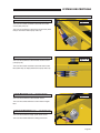
Ramp Manual Operation
If you experience power or equipment failure, the
ramp can be manually stowed and deployed. The
RA300 ramp must be manually operated by an attendant.
Figure A
Keep clear of area
where ramp side plates
VWRZLQSDQÁRRU
Two oval-shaped HAND HOLD slots are provided
on the ramp (see Figure A). Carefully unfold and
fold the ramp using the HAND HOLDs.
Keep clear of
hinged areas.
Keep clear of
tension cables.
Keep clear of the area in which the hinged RA300
ramp sections fold and unfold. Keep clear of the
area where the inboard ramp side plates stow in the
SDQÁRRU.HHSFOHDURIWHQVLRQFDEOHVDQGGULYH
arms. Remember to use good body mechanics
when folding and unfolding the ramp.
The safety precautions addressed in the Ramp
Power Operation section apply to manual operation
of the ramp also. Read and become familiar with
all ramp safety precautions.
Note: Minimal physical effort is required to manually operate the ramp. Slow steady motion results
in the least resistance and easy operation. The
faster you attempt to manually operate the ramp,
the greater the resistance.
Hand
Hold
Keep clear of
hinged areas.
Hand
Hold
Use HAND HOLDs to carefully
unfold and fold the ramp.
Ramp Passenger Safety
Unless your transit agency has a published policy
stating that driver/attendants do not aid ramp
(disabled) passengers, it is the responsibility of
the driver/attendant to ensure that ramp passengers enter and exit the vehicle on the ramp
in the safest manner.
ADA requirements state that transit drivers/attendants must assist with attaching and removing
wheelchair and occupant restraint belts.
Ramp passengers (wheelchair passengers and
standees), and attendants must use common
VHQVHDQGJRRGMXGJPHQWUHJDUGLQJUDPSVDIHW\
Each wheelchair passenger (or standee) has a
unique set of physical abilities combined with the
physical characteristics of his or her wheelchair (or
other mobility aid) that dictate the method in which
he or she will enter and exit the vehicle.
Wheelchair attendants should be instructed on
any special needs and/or procedures required for
safe transport of wheelchair passengers. Follow all
safety instructions regarding torso restraints, stability, balance, weight distribution and use of attenGDQWVDVVSHFLÀHGLQWKHRZQHUҋVPDQXDOVXSSOLHG
with the passenger’s wheelchair (or other mobility
aid). Wheelchair passengers must determine,
establish and practice ramp boarding and exiting
procedures under the direction of the their personal
health care professional and wheelchair representative. Those procedures should be conveyed to the
ramp attendant. Know your passengers abilities
and needs for optimum safety.
Attendants must never operate the vehicle, the
ramp or assist passengers if intoxicated. Intoxicated passengers should not be allowed to board or
exit the vehicle.
Passengers should be positioned in the center of
the ramp at all times. Attendants and ramp passengers must be able to clearly view the ramp
whenever boarding and exiting the vehicle. The
Page 11
RAMP OPERATION
Ramp Passenger Safety (Continued)
WARNING
Position and fasten
the wheelchairequipped occupant
seat belt before
loading onto the
wheelchair ramp.
Failure to do so may
result in serious
bodily injury and/or
property damage.
attendant and/or wheelchair passenger must ensure the ramp is
fully deployed before exiting the
vehicle. Observe your passengers at all times when they are
entering and exiting the vehicle.
Wheelchair-Equipped Occupant
Seat Belts: Wheelchair passengers should position and buckle
their wheelchair-equipped seat
EHOWWRUVRUHVWUDLQWDVVSHFLÀHG
by the manufacturer, before loading onto a wheelchair ramp.
Different types of disabilities
require different types of wheelchairs and different types of
wheelchair-equipped occupant
restraint belt systems (torso restraint). It is the responsibility of
the wheelchair passenger to have
his or her wheelchair equipped
with an occupant restraint (seat
belt) under the direction of their
health care professional.
Page 12
WARNING
Be aware of
ramp slope.
52217
Stabilizing Wheelchairs: Powered and manual wheelchairs
are designed to remain upright
and stable during normal operation. All activities which involve
movement in a wheelchair have
an effect on the combined center
of gravity of the occupant and
wheelchair. Be aware of the ramp
slope (angle). The slope of the
ramp has a direct effect on the
center of gravity. The wheelchair
passenger’s center of gravity and
their ability to maintain stability
and balance must be kept in mind
by the wheelchair passenger and
the attendant.
The aid of an attendant stabilizing
the wheelchair is recommended
for optimum safety. Wheelchair
passengers who are unable to
maintain stability and balance
should not board a ramp without
assistance. Counterbalance
devices (anti-tippers) may be
available from the wheelchair representative to enhance stability
and balance.
Wheelchairs should be operated
at a slow and constant speed
when on the ramp. Wheelchairs
should not accelerate suddenly
when on the ramp. Wheelchair
passengers should not raise the
front wheelchair wheels (pull
wheelie) when on the ramp.
Wheelchair passengers who
intend to enter and exit the
vehicle without the assistance of
an attendant must determine the
safest and most practical method
and orientation of entering and
exiting based on the physical
characteristics of their personal
wheelchair and his or her physical
capabilities to maintain stability
while the wheelchair is in motion
on the ramp.
Wheelchair Attendants: When
assisting a wheelchair occupant,
remember to use good body mechanics. When the wheelchair is
on the ramp, the attendant must
grasp the push handles (or other)
securely. Detachable wheelchair
parts such as arms or leg rests
must never be used for hand
holds or lifting supports. Doing
so could result in the parts being
inadvertently detached from the
wheelchair resulting in possible
injury to the wheelchair occupant and/or the attendant.
RAMP INSTALLATION
Safety Symbols
SAFETY FIRST!
Know That....
All information contained
in this manual and
supplements (if included), is provided for your safety. Familiarity
with proper operation instructions
as well as proper maintenance
procedures are necessary to ensure safe, trouble free operation.
Safety precautions are provided
to identify potentially hazardous
situations and provide instruction
on how to avoid them.
A
D
B
WARNING
This symbol indicates
important safety
information regarding
a potentially hazardous situation that
could result in serious
bodily injury and/or
property damage.
C
CAUTION
This symbol indicates
important information
regarding how to
avoid a hazardous
situation that could
result in minor personal injury or property
damage.
Note:$GGLWLRQDOLQIRUPDWLRQSURYLGHGWRKHOSFODULI\RUGHWDLODVSHFLÀFVXEMHFW
These symbols will appear throughout this manual. Recognize the seriousness of this information.
Installation / Service Safety Precautions
WARNING
If installation, maintenance or repair
procedures cannot
be completed exactly as provided in
this manual or if the
instructions are not
fully understood,
contact The Braun
Corporation immediately. Failure to do
so may result in
serious bodily injury
and/or property
damage.
WARNING
Read this manual and supplement(s) before performing installation, operation or service procedures.
CAUTION ,QVWDOODWLRQVSHFLÀFDWLRQVDQGGLPHQVLRQVPXVWEHPHW
WARNING
Remove any obstructions within the ramp mounting/operating
area prior to beginning installation procedures.
WARNING
Do not operate ramp prior to positive securement of the pan.
WARNING
Check for obstructions such as gas lines, wires, exhaust, etc.
before drilling or cutting during installation procedures.
WARNING
Route all cables clear of exhaust system, other hot areas,
moving parts, wet areas, etc.
WARNING
5LVNRIHOHFWULFDOVKRFNRUÀUH8VHH[WUDFDUHZKHQPDNLQJ
electrical connections. Connect and secure as outlined in
Installation Instructions and Wiring Diagrams.
WARNING
0HHWDOOUDPSSRVLWLRQLQJDQGFOHDUDQFHVSHFLÀFDWLRQVDVGHWDLOHGLQWKH3RVLWLRQLQJDQG
Clearance Checklist before operating ramp.
WARNING
Maintenance and repairs must be performed only by authorized service personnel.
WARNING
Perform maintenance and lubrication procedures exactly as outlined in the Maintenance
and Lubrication Schedule contained in this manual.
Page 13
RAMP INSTALLATION
Installation/Service Safety Precautions (Continued)
WARNING
Disconnect the power cable at the battery prior to servicing.
WARNING
Keep hands, arms and all other body parts clear of moving parts.
WARNING
Never modify (alter) a Braun Corporation ramp.
WARNING
Replacement parts must be Braun authorized replacements.
WARNING
Never install screws or fasteners (other than factory equipped).
WARNING
Whenever replacing a hydraulic cylinder or seals, deploy ramp fully.
WARNING
)DLOXUHWRIROORZWKHVHVDIHW\SUHFDXWLRQVPD\UHVXOWLQVHULRXVERGLO\LQMXU\DQGRUSURSerty damage.
Installation Requirements
Braun RA300 Ramps must be
installed and serviced by a Braun
authorized service representative who has attended and been
FHUWLÀHGE\7KH%UDXQ&RUSRUDtion Sales and Service School for
Braun Mobility Products.
WARNING
Read and become familiar with
the operating instructions and the
installation instructions contained
in this manual before beginning
installation, operation or service
procedures.
Read this manual,
before performing
installation, operation
or service procedures.
Failure to do so may
result in serious
bodily injury and/or
property damage.
Chassis Requirements
The Braun RA300 Ramp is deVLJQHGIRUXVHLQORZÁRRUWUDQVLW
YHKLFOHV$´ÁRRUSRFNHWµPRXQWing hole) built into the chassis/
ÁRRUV\VWHPDOORZVIRUVLPSOHLQstallation (accepts “drop-in” unit).
The Floor Pocket Clear Opening DimensionsDUHVSHFLÀHGRQ
pages 15 and 16. See Figures B,
C, D and E.
The ramp installer must provide
an appropriate framework in the
applicable location in the vehicle
(aligned center with passenger
door opening). Ramp assembly
mounting hardware and/or brackets are directly dependant upon
WKHYHKLFOHFKDVVLVDQG´ÁRRU
Page 14
SRFNHWµFRQÀJXUDWLRQQRWVXSplied).
Slope:7KHSRUWLRQRIWKHÁRRU
where the ramp mounts must
slope at an approximate 8° angle
(see Figure C).
Outboard Support Tube: An
outboard support tube must be
positioned under the outboard
edge of the opening (minimum
1-1/2” x 2” steel tube). See Figures C and D. The recommended
height of the support tube is 12”
above ground level. Kneeling
Vehicles: This dimension measured with suspension lowered.
ADA: Installations with the support tube positioned higher than
12” above ground level may not
comply with ADA ramp slope
requirements.
Some OEM chassis meet these
VSHFLÀFDWLRQV7KH5$UDPS
was designed to conform to these
VSHFLÀFDWLRQV
The ramp pan horizontal borGHUOLSVHWVRQWKHÁRRUSRFNHW
SHULPHWHUIUDPHZRUNVXEÁRRU
HWF7KHÀQLVKHGÁRRULQJFDQEH
cut to conform to the border of the
SDQIRUDÁXVKWUDQVLWLRQVXUIDFH
IURPUDPSWRÁRRU
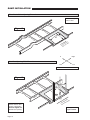
RAMP INSTALLATION
Door Opening: Open the door(s)
fully and check the clear door
opening width dimension. SpeciÀHGPLQLPXPFOHDUGRRURSHQing width must be provided (34"
for 32" ramps and 39-1/2" for 37"
ramps). See Figure F.
Door(s) must open outward.
When closed, the door(s) should
align with and conform to the
outboard edge of the ramp pan
(rubber seal on bottom of door).
Minimum Clear Door Opening
'LPHQVLRQVDUHGHÀQHGDVÀQished door opening, including any
LQWUXVLYHGRRUMDPEVKHDGHUV
sills or hinges.
Obstructions: Any intrusive obstructions within the door opening
or the ramp mounting/operating
area (such as seats, molding,
lights, brackets, etc.) must be removed. Trim or molding that creates an uneven mounting surface
should be removed. The molding
FDQEHPRGLÀHGWRÀWDURXQGWKH
ramp pan horizontal border (lip).
There must be a minimum 1/8”
clearance between the deployed ramp assembly and the
YHKLFOHÁRRURUDQ\REVWUXFWLRQ
RQWKHÁRRUVXFKDVDUXEEHUVLOO
or threshold).
“Floor Pocket” Clear Opening Dimensions
Outboard Support Tube: Recommended Height: 12” above ground
level. Kneeling Vehicles (measured
with suspension lowered).
ADA: Installations with support tube
positioned higher than 12” above
ground level may not comply with
ADA ramp slope requirements.
Figure B
7KHSRUWLRQRIWKHÁRRUZKHUHWKH
ramp mounts must slope at an approximate 8° angle.
Figure C
Outboard
Support Tube
SH Ý
)ORRU6OR
12"
BF3248Y & BF3248YP 34-3/4"
BF3748Y 39-3/4"
Ý
23"
Figure D
Structure: Minimum
1-1/2” x 2” steel tubing (or equivalent).
Floor Pocket
Framework
is
ass
Ch
E
UB
TT
OR
PP
SU
Outboard
Support Tube
Page 15
RAMP INSTALLATION
"Floor Pocket" Clear Opening Dimensions
Note: See Figure
B and C also.
Figure E
23
"
ket
Poc h
r
o
o
Fl Widt
is
ass
Ch
E
UB
TT
th: p
Wid
ket 2" Ram mp
c
o
rP r3
Ra
Floo 3/4" fo or 37"
34- -3/4" f
39
OR
PP
SU
In
Right
Left
Out
Clear Door Opening Width Dimension
As viewed from outside the vehicle
Figure F
is
ass
Ch
M
IMU ING
MIN PEN
O
OR TH
DO WID
CL
is
ass
Ch
9HKLFOHFKDVVLV´ÁRRU
SRFNHWµFRQÀJXUDWLRQ
must be aligned center with door opening.
Page 16
CL
th:
Wid
g
n
ni
Ope amp p
oor 32" R " Ram
D
m
r
imu 34" fo for 37
Min
/2"
39-1
Door(s) must
open outward.
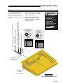
RAMP INSTALLATION
Installed Ramp - Stowed
Figure G
is
ass
Ch
is
ass
Ch
E
UB
TT
OR
PP
SU
Stowed RA300
Ramp positioned in
WKH´ÁRRUSRFNHWµ
In
Right
Left
Out
Installed Ramp - Deployed
As viewed from outside the vehicle
Figure H
is
ass
Ch
®
is
ass
Ch
E
UB
TT
OR
PP
SU
There must be a minimum 1/8” clearance
between the deployed ramp assembly and
WKHYHKLFOHÁRRURUDQ\REVWUXFWLRQ on the
ÁRRUVXFKDVDUXEEHUVLOORUWKUHVKROG
Page 17
RAMP INSTALLATION
Electrical Connections
An 8-pin Deutsch connector
is mounted at the back of the
RA300 ramp. A mating connector
(male plug) is supplied with the
ramp. The power supply (12 volt
or 24 volt), the ground, a ramp
OUT signal (+) and a ramp IN signal (+) must be terminated in the
supplied Deutsch connector.
The ramp installer provides an
appropriate control switch for the
end user. A momentary contact
ramp control switch (center off)
will typically be mounted near the
driver. The control switch may
be part of a panel providing other
features and controls (power on/
off indicators, LED’s, etc.).
Make electrical connections as
shown in Figure K page 19. Strip
wires, crimp and install contacts
DVVSHFLÀHGLQLQVWUXFWLRQVVXSplied with 8-pin Deutsch connector.
The Positive (+) “battery” lead wire must
be protected by an in-line 30 ampere
fuse or circuit breaker (installer provided).
Figure J
Cable
Clip
Do not connect the power “battery” lead
wire to the battery until all other connections are made.
WARNING
Route cables clear
of exhaust system,
other hot areas and
moving parts. Failure
to do so may result
in serious bodily
injury and/or property
damage.
Secure all cables using cable
ties and/or cable clips (mount
clips with self-tap screws).
Cable
(typical)
Connect the 8-pin Deutsch male plug to
the mating Deutsch connector mounted
at the back of the pan.
Cable Tie
Carefully connect the power “battery”
lead wire to the Positive (+) battery post.
Vehicle
Floor
Framing
Member
WARNING
Risk of electrical
shock! Use extra
care when making
electrical connections.
Page 18
Vehicle
Floor
WARNING
5LVNRIHOHFWULFDOÀUH
Use extra care when
making electrical
connections.
Self-Tap Screw
Chassis Ground Corrosion:
When mounting chassis ground
cables, remove undercoating, dirt,
rust, etc. from the framing member
around the mounting holes. Apply
a protective coating to mounting
holes to prevent corrosion. Apply
grease to ground cable terminals
and mounting hardware. Failure
to do so will void warranty of
certain electrical components.
RAMP INSTALLATION
Electrical Connections
An 8-pin Deutsch connector (male
plug) is supplied with the ramp.
WARNING
Positive (+) battery
lead wire must be
protected by
installer-provided 30
ampere fuse or
circuit breaker.
Failure to do so may
result in serious
bodily injury and/or
property damage.
The Positive (+) “battery” lead wire
must be protected by an in-line
30 ampere fuse or circuit breaker
(installer provided).
BF3248Y & BF3748Y
BF3248YP
CONNECTOR - P1
(B.C.# 30136)
CONNECTOR - P1
(B.C.# 30136)
TO SIGNAL TO RAMP STOW INDICATOR
E D C
TO SIGNAL TO RAMP DEPLOY INDICATOR
TO USER CONTROL SIGNAL TO DEPLOY RAMP - (MOMENTARY SWITCH)
TO USER CONTROL SIGNAL IGNITION/MANUAL RELEASE - BF3248YP ONLY
TO USER CONTROL SIGNAL TO STOW RAMP
TO POWER SOURCE - (30 AMP. CURCUIT PROTECTION DEVICE)
TO VEHICLE GROUND
The ramp installer provides an appropriate momentary contact control
switch.
Terminate the power supply, ground,
ramp OUT signal and ramp IN signal
DVVSHFLÀHGLQOHJHQG
A B
F G H
E D C
A B
F G H
WIRING PROVIDED
BY INSTALLER
OR
WIRING PROVIDED
BY INSTALLER
8-COND WIRE CODE
PIN
COLOR
8-COND WIRE CODE
A
POWER SOURCE - 12 GA.*
B
VEHICLE GROUND - 12 GA.*
C
TO USER STOW - 16 GA.*
A
POWER SOURCE - 12 GA.*
TO USER DEPLOY - 16 GA.*
B
VEHICLE GROUND - 12 GA.*
D
PIN
COLOR
C
TO USER STOW - 16 GA.*
F
PLUG - NOT USED
D
TO USER DEPLOY - 16 GA.*
G
RAMP STOW SIGNAL - 16 GA.*
E
H
RAMP DEPLOY SIGNAL - 16 GA.*
E
PLUG - NOT USED
* RECOMMENDED WIRE GAUGE
PLUG - NOT USED
F
USER IGN/MAN REL. - 16 GA.*
G
RAMP STOW SIGNAL - 16 GA.*
H
RAMP DEPLOY SIGNAL - 16GA.*
* RECOMMENDED WIRE GAUGE
8-pin Deutsch
Male Plug
(supplied with ramp)
8-pin Deutsch
Connector
(ramp equipped)
Figure K
Electrical Connections Illustration
Page 19
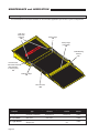
MAINTENANCE and LUBRICATION
Lubrication Diagram
See the Maintenance/Lubrication Schedule for recommended applications per number of cycles or elapsed time.
Gear and
Gear Rack
(internal)
DE
Ramp Hinge
LO
Ramp Hinge
(concealed)
LO
®
Cable Bearing
Surface
LO
Drive Arm and
Cam Gear Shaft
(after Smooths
or 1200 Cycles)
LO
Cable at Pulleys
LO
Drive Arm Slot
DE
Lubricant
LO - Light Oil
Type
Light Penetrating Oil
(30 weight or equivalent)
6SHFLÀHGUHFRPPHQGHG
Lubricant
$YDLODEOH
Amount
%UDXQ
Part No.
LPS2, General Purpose
Penetrating Oil
11 oz.
Aerosol Can
15807
DE - Door-Ease
Stainless Stick
Style (tube)
Door-Ease
Stick (tube)
1.68 oz.
LG - Light Grease
Light Grease
(Multipurpose)
Lubricate
14 oz.
Can
Page 20
15806
15805
MAINTENANCE and LUBRICATION
Maintenance and Lubrication Introduction
Proper maintenance is necessary to ensure safe,
trouble-free operation. Inspecting the ramp for
any wear, damage or other abnormal conditions
should be a part of all transit agencies daily service
program (preventive maintenance). Simple inspections can detect potential problems.
A generic Daily Preventive Maintenance Schedule is provided in this manual for transit agency
use. The form can be tailored to your particular
application. Preventive maintenance visual inspections do not take the place of the procedures speciÀHGLQWKLVVFKHGXOH
The maintenance and lubrication procedures speciÀHGLQWKLVVFKHGXOHmust be performed by a Braun
authorized service representative at the scheduled
intervals according to the number of cycles or
HODSVHGWLPHZKLFKHYHUFRPHVÀUVW
RA300 Ramps are equipped with hardened pins
and self-lubricating bearings to decrease wear,
provide smooth operation and extend the service
life of the ramp.
Clean the components and the surrounding area
before applying lubricants. LPS2 General Purpose Penetrating Oil is recommended where Light
Oil is called out. Use of improper lubricants can
attract dirt or other contaminants which could result
in wear or damage to the components. Ramp components exposed to contaminants when lowered to
WKHJURXQGPD\UHTXLUHH[WUDDWWHQWLRQ6SHFLÀHG
lubricants are available from The Braun Corporation
(part numbers provided on page 20).
cedures and will vary
WARNING
according to ramp use
and conditions. Transit
Maintenance and luagencies operating
brication procedures
vehicles equipped with
must be performed
ramps that are not
DVVSHFLÀHGE\DQ
monitored by cycles
may choose to have
authorized service
the ramp system maintechnician.
tained on the same
Failure to do so may
schedule as the vehicle
result in serious
(routine maintenance).
bodily injury and/or
Doing so ensures the
property damage.
ramp is being maintained regularly.
When servicing the ramp at the consecutive recommended intervals, inspection and lubrication proceGXUHVVSHFLÀHGLQWKHSUHYLRXVVHFWLRQVVKRXOGEH
performed (repeated). All listed inspection, lubrication
and maintenance procedures should be repeated at “8
Weeks or 200 Cycles” intervals following the scheduled
“1 Year or 1250 Cycles” maintenance.
Lifts exposed to severe conditions (weather, environment, contamination, heavy usage, etc.) may require
inspection and maintenance procedures to be perIRUPHGPRUHRIWHQWKDQVSHFLÀHG
Discontinue ramp use immediately if maintenance
and lubrication procedures are not properly performed,
or if there is any sign of wear, damage or improper
operation. Contact your sales representative or call
The Braun Corporation at 1-800-THE LIFT®. One of
our national Product Support representatives will direct
you to an authorized service technician who will inspect
your ramp.
Recommended Intervals: These intervals are a
general guideline for scheduling maintenance pro-
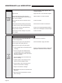
Maintenance and Lubrication Schedule
8 Weeks
or 200
Cycles
Inboard ramp hinge
Clean and lubricate. Apply Light Oil - See
Lubrication Diagram
Outboard ramp hinge
Clean and lubricate. Apply Light Oil - See
Lubrication Diagram
Drive arm pivot pins (screws, nuts and bearings)
Apply Light Oil - See Lubrication Diagram
Drive arm and cam gear pivot shaft
Apply Light Oil - See Lubrication Diagram
continued
Page 21
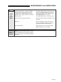
MAINTENANCE and LUBRICATION
continued
8 Weeks
or 200
Cycles
Cable at pulley and hinge areas
Clean and lubricate. Apply Light Oil - See
Lubrication Diagram
Drive arm slot
Apply Door-Ease. See Lubrication Diagram
Inspect drive arm pivot points (mounting
screws, nuts and bearings) for positive securement, wear or damage
Tighten, replace or correct as needed.
Inspect drive arm slots for excessive wear or
damage
Correct as needed
Clean ramp and ramp mounting area (ensure
no debris in area to obstruct stowing/stacking)
Clean and remove debris or obstructions
Cycle ramp and observe drift speed during
deploy and stow functions
,IGULIWVWRRIDVWDGMXVWDSSOLFDEOH'ULIW0LFURswitch Cam so drift begins at reduced height.
Inspect ramp for wear, damage or any abnormal condition.
Correct as needed
Perform all procedures listed in previous section also
5HPRYHVXEÁRRUSDQFRYHUDQGFOHDQGLUW
and other foreign debris
Blow out with air compressor
5HPRYHVXEÁRRUSDQFRYHUDQGOXEULFDWH
drive arm gear and cylinder gear rack
Clean and lubricate. Apply Door-Ease
5HPRYHVXEÁRRUSDQFRYHUDQGLQVSHFW
• Pump mounting bolts for securement (loose
or missing)
1 Year
or
1250
Cycles
• Drive arm and gear rack weldment teeth
IRUIRUHLJQREMHFWVZHDURUGDPDJHEHQW
deformed, misaligned), positive securement
and proper operation
• Gear rack weldment pin securement E-clip
(loose or missing)
+\GUDXOLFF\OLQGHUKRVHVÀWWLQJVDQGFRQnections for wear, damage or leaks
• Harness cables, wires, terminals and connections for securement or damage
• Relays for securement or damage
• Microswitches and cams for securement and
DGMXVWPHQW
• Microswitch wires and terminals for securement or damage
Page 22
5HVHFXUHDGMXVWPLFURVZLWFKHVUHSODFHGDPaged parts or otherwise correct as needed.
MAINTENANCE and LUBRICATION
continued
1 Year
or
1250
Cycles
Consecutive
8 Week or
200 Cycle
Intervals
Hydraulic Fluid (Pump) - Check level. Note:
Fluid should be changed if there is visible
contamination. Inspect the hydraulic system
F\OLQGHUKRVHVÀWWLQJVVHDOVHWFIRUOHDNVLI
ÁXLGOHYHOLVORZ
Use Braun 32840-QT (Exxon® Univis HVI 26)
K\GUDXOLFÁXLGdo not mix with Dextron III or
RWKHUK\GUDXOLFÁXLGV&KHFNÁXLGOHYHOZLWK
ramp deployed fully. Fill to within
µRIWKHERWWRPRIWKHµÀOOWXEHQHFN
Inspect vehicle-to-ramp wiring harness
Resecure, repair or replace or otherwise correct
as needed
Mounting
Check to see that the ramp is securely anchored to the vehicle and there are no loose
bolts, broken welds, or stress fractures.
Decals and Antiskid
Replace decals if worn, missing or illegible.
Replace antiskid if worn or missing.
Repeat all previously listed inspection, lubrication and maintenance procedures at 8 week or
200 cycle intervals (or per vehicle maintenance
schedule).
Page 23
SYSTEMS DESCRIPTIONS
Electrical
WARNING
Improper microswitch
adjustment may result in serious bodily
injury and/or property
damage.
Microswitches: Three microswitches (limit switches) are
incorporated in the RA300 Ramp
electrical system. "Y" ramp models microswitches are: Drift-In,
Drift-Out and Counter. The "YP"
ramp model also has three microswitches: Drift-In, Drift-Out and
Power Down Activation. Details
and photos of the microswitches
DUHSURYLGHGEHORZ$GMXVW
microswitch(es) as detailed (if
necessary only).
downward to ground level, during
which, at some position, the DriftOut microswitch is activated. The
Drift-In microswitch is deactivated
during the deploy movement of
the platform. Note, however,
that neither of the other 2 microswitches have any bearing on the
deploy sequence.
When the ramp’s platform reaches the Drift-Out limit (approx. 45°
above ground level) and deactivates the microswitch, the current
to the Stow Relay will be interrupted.
Microswitch Sequence
Stowed Position: When the
ramp is in the stowed position, the Drift-Out and Counter
microswitches are deactivated
(common and normally closed
terminals have continuity). In
contrast, the Drift-In microswitch
is activated.
Deploy Sequence: When the
ramp is in the stowed position, the
Drift-Out microswitch is deactivated. Current is allowed to pass
from the vehicle Deploy Relay,
which directs current to the Bidirectional Pump motor in direction
A (hydraulically drives cylinders to
deploy ramp).
When the ramp’s platform reaches the Drift-In limit (approx. 45°
above ground level), the microswitch is activated (common and
normally open terminals have
continuity), and the current to the
Deploy Relay is interrupted thus
stopping the current to the pump
motor. The platform then “drifts”
Page 24
Deployed Position: When the
ramp is in the deployed position, the Drift-Out and Counter
microswitches are activated. In
contrast, the Drift-In microswitch
is deactivated.
Stow Sequence: When the
ramp is in the deployed position, the Drift-In microswitch is
deactivated, allowing current to
pass from the vehicle Stow switch
circuit and energize the ramp
Stow Relay, which directs current
to the Bidirectional Pump motor
in direction B (hydraulically drives
cylinder to stow ramp).
"Y" Models Only: When the
ramp’s platform reaches the
Drift-In limit (approx. 15° above
YHKLFOHÁRRUOHYHOWKHPLFURswitch is activated and the current
to the Stow Relay is interrupted
thus stopping the current to the
pump motor. The platform then
“drifts” downward to the vehicle
ÁRRU7KH'ULIW2XWPLFURVZLWFKLV
also deactivated during the stow
movement of the platform
SYSTEMS DESCRIPTIONS
Electrical (Continued)
Drift In Microswitch (Cam 1 - All RA300 Models)
Figure L
Turn Cam #1 counter-clockwise to start Drift In function
sooner (shut pump off).
Turn Cam #1 clockwise to start Drift In function later (allow
ramp to stow further before pump shuts off).
3
2
1
Drift Out Microswitch (Cam 2 - All RA300 Models)
Figure M
Turn Cam #2 clockwise to start Drift Out function sooner
(shut pump off).
Turn Cam #2 counter-clockwise to start Drift Out function
later (allow ramp to deploy further before pump shuts off).
1
2
3
Counter Microswitch (Cam 3 - All RA300 Models)
Figure N
Turn Cam #3 clockwise to start Interlock sooner.
Turn Cam #3 counterclockwise to return Interlock signal
later.
Power Down Microswitch (Cam 3 - "YP" Models Only)
1
2 3
Turn Cam #3 clockwise to begin power down sooner.
Turn Cam #3 counterclockwise to delay power down.
Page 25
SYSTEMS DESCRIPTIONS
Hydraulics
M-2202-0102 Hydraulic Pump:
Fixed displacement external gear
type hydraulic pump with 12 VDC
electric motor and 76 cubic inch
ÁXLGUHVHUYRLUIRU9%)<
and 12V BF3748Y. The Braun
Pump Code for 12 volt M-22020102 pumps is 59.
M-2202-0102 Hydraulic Pump:
Fixed displacement external gear
type hydraulic pump with 24 VDC
electric motor and 76 cubic inch
ÁXLGUHVHUYRLUIRU9%)<
and 24V BF3748Y. The Braun
Pump Code for 24 volt M-22020102 pumps is 60.
B-3202-0100 Hydraulic Pump:
Fixed displacement external gear
type hydraulic pump with 12 VDC
electric motor and 76 cubic inch
ÁXLGUHVHUYRLUIRU9%)<3
The Braun Pump Code for 12 volt
B-3202-0100 pumps is 67.
All RA300 Hydraulic Pumps:
The Deploy pressure relief valve
is factory set at 1000 psi. The
Stow pressure relief valve is factory set at 1250 psi.
Hydraulic Fluid: Use Braun
32840-QT (Exxon® Univis HVI 26)
K\GUDXOLFÁXLGDo not mix with
'H[WURQ,,,RURWKHUK\GUDXOLFÁXids. Make sure the ramp is fully
deployedZKHQFKHFNLQJÁXLG
OHYHORUDGGLQJÁXLG)LOOWRZLWKLQ
1" of the top of the reservoir. DO
NOT XVHDVROLGSOXJRUÀOOFDS
without a breather hole. Doing so
will result in pump and/or reservoir damage.
Contamination: Fluid should be
changed if there is visible contamination. Inspect the hydraulic
V\VWHPF\OLQGHUKRVHVÀWWLQJV
VHDOVHWFIRUOHDNVLIÁXLGOHYHO
is low.
Deploy and Stow Pressure Relief Valves
7KHVHDGMXVWPHQWVRQWKHSXPSXQLWOLPLWWKHPD[LPXPRLOSUHVVXUHLQWKH
system to a safe level. It also keeps the amp draw and battery drain at a
minimum when the cylinders reach full stroke.
The Deploy pressure relief valve is preset at 1000 psi. The Stow pressure
relief valve is preset at 1250 psi. Do not WDPSHUZLWKWKLVDGMXVWPHQWXQOHVV
absolutely necessary (will not stow or deploy ramp) and then, only after
contacting The Braun Corporation. Note:7KHÀ[HGQXWRQHDFKDGMXVWPHQW
Allen screw is positioned to limit oil pressure to a maximum (Deploy relief
valve maximum 1450 psi and Stow relief valve maximum 1700 psi). Do not
DWWHPSWWRORRVHQRUUHPRYHWKHRXWHUÀ[HGQXW
WARNING
Contact The Braun
Corporation before
adjusting hydraulic
pressure relief valve.
Failure to do so may
result in serious
bodily injury and/or
property damage.
Relief Valve Access:7KHUDPSSDQFRYHUVXEÁRRUPXVWEHUHPRYHGWR
access the relief valve (access hole not provided).
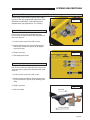
Relief Valve Adjustment Procedure
1. Insert a 3/16” Allen wrench into the Allen screw.
6HFXUHWKH$OOHQVFUHZDQGORRVHQWKHKH[MDP
QXWLQVLGHQXW%DFNMDPQXWRXWWRRXWHUÀ[HG
nut. Note: Do not attempt to loosen or remove
WKHRXWHUÀ[HGQXW
Stow Pressure
Relief Valve
Hex Jamb Nut
2. Place load on platform (equal to weight not lifting).
3. Turn the Allen screw clockwise until pump lifts the
load.
4. Secure the Allen head screw and tighten the hex
MDPQXWLQVLGHQXWsecurely.
Page 26
Allen Screw
Deploy Pressure
Relief Valves
Figure P
SYSTEMS DESCRIPTIONS
Drift IN and OUT Cam Adjustment Procedures ("Y" Ramp Models Only)
RA300 ramp models featuring gravity down deploy
DQGVWRZGULIWDUHHTXLSSHGZLWKDGMXVWPHQWFDPV
%)<DQG%)<$GMXVWGULIWVSHHGDV
detailed below (not applicable for "YP" models).
Figure Q
Drift OUT Speed (Cam 1):
1
2
Drift out cam controls the speed that the ramp
moves when the ramp is almost fully deployed and
the motor shuts off.
1. Loosen the set screw in the drift out cam.
2. Rotate clockwise to slow down the deployment
and counter-clockwise to speed up the deployment of the ramp.
3. Tighten set screw.
Figure R
4. Test deployment speed.
1
Drift IN Speed (Cam 2):
2
Drift in cam controls the speed that the ramp moves
when the ramp is almost fully stowed and the motor
shuts off.
1. Loosen the set screw in the drift in cam.
2. Rotate counter-clockwise to slow down the stowing and clockwise to speed up the stowing of the
ramp.
3. Tighten set screw.
4. Test stow speed.
Figure S
Clockwise
2
Counter-Clockwise
Page 27
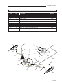
TROUBLESHOOTING
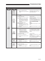
Troubleshooting Diagnosis Chart
WARNING
Troubleshooting and
repair procedures
must be performed
DVVSHFLÀHGE\DQ
authorized service
technician only.
Failure to do so may
result in serious
bodily injury and/or
property damage.
FUNCTION
If a problem occurs with your
ramp, discontinue operation
immediately! Contact your sales
representative or call The Braun
Corporation at 1-800-THE LIFT®.
One of our national Product Support representatives will direct you
to an authorized service technician who will inspect your ramp.
The cause of the problem can
be determined by locating the lift
function and related symptom in
the Troubleshooting Diagnosis
SYMPTOM
1.10
No Power
To Ramp
POSSIBLE CAUSE
continued
Page 28
2.10
No
Operation
continued
REMEDY
Clean and tighten
Clean and tighten. See Chassis Ground
Corrosion on page 18.
Replace
Charge battery
Replace fuse
Check for loose terminals or broken wire
Correct or replace
Disconnect harness from ramp. Using
volt meter, test (probe) 8-pin Deutsch
male plug terminals as follows:
Pin A = +12/24 V
Pin B = -Ground
Pin C = V (when Stow switch is activated)
Pin D = V (when Deploy switch is activated)
1.21 Ramp wiring harness
Remove relays from sockets. Using volt
meter, test (probe) wires/terminals at
relay sockets:
Red = +12/24 V
Black = -Ground
Blue = V (when Stow switch is activated)
Orange = V (when Deploy switch is
activated)
Replace
Clean and tighten
Repair
Crimp tightly to wire
1.00
NO
OPERATION
2.00
DEPLOY
(Out)
A Repair Parts section with an
exploded view and corresponding
parts list is also provided. Correct
the problem if possible. If the
problem continues, contact The
Braun Corporation.
1.11 Battery terminals dirty
1.12 Chassis ground connection (frame
ground cables)
1.13 Battery damaged
1.14 Battery discharged
1.15 25 ampere in-line fuse faulty
1.16 Power cable
1.17 Vehicle Interlock(s) circuit incomplete
1.18 Vehicle-to-ramp wiring harness
(Circuit Problem)
1.20
Power to
Ramp But
No Pump
Operation
&KDUW7KHVSHFLÀFFDXVHDQG
remedy can then be determined
by process of elimination. Wiring
Diagrams, Electrical Schematics,
Hydraulic Diagrams and Hydraulic Schematics are provided to aid
in troubleshooting.
1.22
1.22
1.24
1.25
Faulty relay(s)
Loose connection(s)
Broken wire(s)
Wire terminal(s)
2.11 See 1.00
'ULIW2XW0LFURVZLWFKRXWRIDGMXVWment or damaged
2.13 Drift Out Microswitch harness disconnected, damaged or otherwise
damaged
2.14 Pump motor brushes worn
See Microswitches in Systems Descriptions for details
Connect, repair or replace
Contact Braun Product Support - replace
pump
TROUBLESHOOTING
FUNCTION
SYMPTOM
continued
continued
POSSIBLE CAUSE
REMEDY
2.20
Locked in
Intermediate
Position
2.21 Ramp was stopped within the
Deploy “Drift Out” range during Stow
function
Activate Stow function until ramp is out
of the Deploy “Drift Out” range. Then
activate Deploy function.
2.31 Physical obstruction (20 lb or more)
on ramp
2.32 Mechanical binding
2.33 Deploy pressure relief valve setting
too low
/RZK\GUDXOLFÁXLGVXSSO\Note:
Fluid should be changed if there is
visible contamination. Inspect the
K\GUDXOLFV\VWHPIRUOHDNVLIÁXLG
level is low.
2.35 Leak in hydraulic system
2.36 Cylinder leak
2.37 Deploy pressure relief valve stuck
open due to contamination or otherwise damaged
2.38 Pump internal shuttle valve stuck or
damaged
Remove obstruction
(No Response to
Deploy Switch/No
Drift Out)
2.30
Pump Runs
But
Doesn’t
Deploy
2.00
DEPLOY
(Out)
2.40
Faulty or
Sluggish
Operation
2.41 Lack of lubrication (drive arm assembly pivot pins and shaft)
2.42 Misalignment or damage to:
• Drive arm and/or pivot pins
• Linkage arms and/or pivot pins
• Drive arm and cam gear shaft
• Cylinder rack gear and/or cam gear
2.43 Mechanical binding
2.44 Restriction in hydraulic lines
+\GUDXOLFÁXLGWRRWKLFNGXHWRFROG
climate
Check and correct
$GMXVWUHOLHIYDOYHVHWWLQJ6HH6\VWHPV
Descriptions for details.
Use Braun 32840-QT (Exxon® Univis HVI
K\GUDXOLFÁXLGdo not mix with DexWURQ,,,RURWKHUK\GUDXOLFÁXLGV&KHFN
oil level with ramp fully deployed. See
Systems Descriptions for details.
Repair
Replace.
Contact Braun Product Support - replace
pump
Contact Braun Product Support - replace
pump
Lubricate pivot pins. See Maintenance
and Lubrication Schedule and Diagram
Correct/Replace/Lubricate. See Maintenance and Lubrication Schedule and
Diagram
Check and correct
Check for contamination or kinks - correct
or replace
Thin with Diesel fuel - 2 T. Change in
spring. See Systems Descriptions for fullWLPHFROGFOLPDWHVSHFLÀFDWLRQV
2.50 Drifts
Excessively
Slow
(or No Drift)
2.51 See 2.38 and 2.40
3XPSLQWHUQDORULÀFHSOXJJHGRU
damaged
'ULIWRXWFDPQHHGVDGMXVWPHQW
Contact Braun Product Support - replace
pump
6HHGULIWFDPDGMXVWPHQWSURFHGXUH
2.60
Drifts
Excessively
Fast
2.61 See 2.35 and 2.36
3XPSLQWHUQDORULÀFHHQODUJHGRU
damaged
'ULIWRXUFDPQHHGVDGMXVWPHQW
Contact Braun Product Support - replace
pump
6HHGULIWFDPDGMXVWPHQWSURFHGXUH
Page 29
TROUBLESHOOTING
FUNCTION
SYMPTOM
3.10
No
Operation
POSSIBLE CAUSE
3.11 See 1.00
'ULIW,Q0LFURVZLWFKRXWRIDGMXVWment or damaged
3.13 Drift In Microswitch harness disconnected, damaged or otherwise
damaged
REMEDY
$GMXVWRUUHSODFH6HH0LFURVZLWFKHVLQ
Systems Descriptions for details
Connect, repair or replace
3.20
Locked in
Intermediate
Position
(No Response to
Stow Switch/No
Drift In)
3.00
STOW
(In)
3.40
Pump Runs
But
Doesn’t
Stow
3.50
Faulty or
Sluggish
Operation
3.60
Drifts
Excessively
Slow
(or No Drift)
3.21 Ramp was stopped within the Stow
“Drift In” range during Deploy function ("Y" models only)
Activate Deploy function until ramp is
out of the Stow “Drift In” range. Then
activate Stow function.
3.41 See 2.31, 2.32, 2.34, 2.35 and 2.36
3.42 Stow pressure relief valve setting
too low
3.43 Stow pressure relief valve stuck
open due to contamination or otherwise damaged
$GMXVWUHOLHIYDOYHVHWWLQJ6HH6\VWHPV
Descriptions for details.
Contact Braun Product Support - replace pump
4.51 See 2.40
4.61 See 2.40 and 2.50
4.71 See 2.35, 2.36 and 2.62
3.70
Drifts
Excessively
Fast
Page 30
BLANK for LAYOUT
Page 31
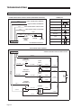
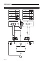
TROUBLESHOOTING
Electrical Schematic - BF3248Y & BF3748Y
SYMBOL KEY
POWER CONNECTIONS / CONTROL SIGNALS (PROVIDED BY INSTALLER)
DESCRIPTION
16 GA. *
SYMBOL
SIGNAL TO RAMP DEPLOY INDICATOR
BATTERY
16 GA. *
SIGNAL TO RAMP STOW INDICATOR
CHASSIS GROUND
16 GA. *
USER CONTROL SIGNAL TO DEPLOY RAMP
CIRCUIT PROTECTION DEVICE
16 GA. *
USER CONTROL SIGNAL TO STOW RAMP
JUNCTION
12 GA. *
GROUND
NO
MICROSWITCH
P1
H
G
F
E
D
C
B
A
12 GA. *
C
NC
12 GA. *
85
RELAY
CIRCUIT
PROTECTION
DEVICE
(25 AMP.)
86
87
30
87A
BATTERY
GROUND
MOTOR
M
1
4
2
3
COUNTER
* RECOMMENDED WIRE GUAGE
RA300 TRANSIT RAMP ASSEMBLY
J1
H
G
F
E
D
C
B
A
DRAWING SHOWN WITH RAMP IN STOWED POSITION
12 GA. RD
STOW
RELAY
NO
16 GA. BN/BK
C
85
16 GA. BL/BK
86
12 GA. BK
12 GA. RD
30
87
87A
12 GA. BK
"DRIFT OUT"
MICROSWITCH
DEPLOY
RELAY
NO
16 GA. OR/BK
C
NC
12 GA. BU
12 GA. RD
85
16 GA. OR/BK
86
PUMP
16 GA. YL
16 GA. WH
16 GA. OR/BK
NC
12 GA. BK
"DRIFT IN"
MICROSWITCH
12 GA. RD
16 GA. BN/BK
12 GA. BK
12 GA. BK
12 GA. RD
30
87
87A
12 GA. BK
"COUNTER"
MICROSWITCH
12 GA. OR
12 GA. RD
COUNTER
C
NC
16 GA. YL/WH
1
4
COUNT
NEG
N/A
POS
12 GA. RD
NO
12 GA. BK
16 GA. YL
12 GA. BK
16 GA. WH
2
12 GA. RD
Page 32
3
12 GA. RD
M
87
87a
30
COLOR
87
87a
3
COLOR
PLUG - NOT USED
TO STOW INDICATOR - 16 GA.*
BLACK - 12 GA.
"DRIFT OUT"
MICROSWITCH
WHITE - 14 GA.
MOTOR - ORANGE
ORANGE / BLACK - 16 GA.
BLACK - 12 GA.
RED - 12 GA.
BLACK - 12 GA.
30
85
86
87
87a
COLOR
LOC.
COLOR
ORANGE / BLACK - 16 GA.
NOT USED
N.O.
COM.
N.O.
N.C.
"COUNTER"
MICROSWITCH
WHITE - 16 GA.
RED - 12 GA.
COM.
COLOR
YELLOW / WHITE - 16 GA.
N.C.
N.O.
PIN
MICROSWITCH CONN.
ORANGE / BLACK - 16 GA.
N.C.
COM.
PIN
MICROSWITCH CONN.
COM.
N.O.
N.C.
COM.
N.O.
BLACK - 12 GA.
N.C.
BROWN / BLACK - 16 GA.
NOT USED
BLUE / BLACK - 16 GA.
COLOR
MICROSWITCH CONN.
PIN
YELLOW - 14GA.
G
H
N.C.
N.O.
PLUG - NOT USED
PLUG - NOT USED
COM.
ORANGE / BLACK - 14 GA.
"DRIFT IN"
MICROSWITCH
F
BLACK - 12 GA.
4
E
D
COLOR
2C3 RED - 12 GA.
BLUE / BLACK - 14 GA.
A
B
C
PIN
8-COND WIRE CODE
A B
F G H
RED - 12 GA.
* RECOMMENDED WIRE GAUGE
TO DEPLOY INDICATOR - 16 GA.*
F
H
PLUG - NOT USED
D
G
USER STOW SIGNAL - 16 GA.*
USER DEPLOY SIGNAL - 16 GA.*
C
E
NOT USED
RED - 12 GA.
3
YELLOW / WHITE - 16 GA.
2
1
POWER SOURCE - 12 GA.*
VEHICLE GROUND - 12 GA.*
LOC.
A
E D C
POS
4
COUNTER - WIRE CODE
N/A
NEG
B
CONNECTOR - J1
2
COUNT
COLOR
PIN
8-COND WIRE CODE
WIRING PROVIDED
BY INSTALLER
A B
F G H
E D C
COUNTER
BLACK - 12 GA.
RELAY #1 - WIRE CODE
85
30
1
BLUE / BLACK - 16 GA.
MOTOR - BLUE
86
DEPLOY RELAY
(RELAY - 1)
87a
87
86
85
30
LOC.
RELAY #2 - WIRE CODE
85
STOW RELAY
(RELAY - 2)
86
CONNECTOR - P1
(B.C.# 30136)
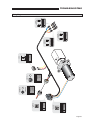
TROUBLESHOOTING
Wiring Diagram - BF3248Y & BF3748Y
Page 33
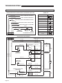
TROUBLESHOOTING
Electrical Schematic - BF3248YP
POWER CONNECTIONS / CONTROL SIGNALS (PROVIDED BY INSTALLER)
SYMBOL KEY
DESCRIPTION
12 GA. or 14 GA. *
SYMBOL
SIGNAL TO RAMP DEPLOY INDICATOR
BATTERY
12 GA. or 14 GA. *
SIGNAL TO RAMP STOW INDICATOR
CHASSIS GROUND
USER CONTROL SIGNAL IGNITION/MANUAL RELEASE
CIRCUIT PROTECTION DEVICE
(5 AMP.)
12 GA. or 16 GA. *
JUNCTION
USER CONTROL SIGNAL TO DEPLOY RAMP
NO
MICROSWITCH
12 GA. or 14 GA. *
12 GA. or 16 GA. *
C
USER CONTROL SIGNAL TO STOW RAMP
NC
85
RELAY
12 GA. *
86
87
30
GROUND
87A
COIL
12 GA. *
12 GA. *
DIODE
P1
H
G
F
E
D
C
B
A
CIRCUIT
PROTECTION
DEVICE (30 AMP.)
BATTERY
GROUND
M
MOTOR
* RECOMMENDED WIRE GAUGE
1
4
2
3
COUNTER
J1
H
G
F
E
D
C
B
A
RA300 TRANSIT RAMP ASSEMBLY
DRAWING SHOWN WITH RAMP IN STOWED POSITION
RD - 12 GA.
RD - 12 GA.
BK - 12 GA.
BK - 12 GA.
BL/BK - 14 GA.
BL/BK - 18 GA.
PRESSURE SWITCH
BL/BK - 14 GA.
BL/BK - 14 GA.
NO
85
NC
86
COIL
A
RELAY 1
C
BK - 12 GA.
RD - 12 GA.
87
BK - 16 GA.
87A
"DRIFT IN"
MICROSWITCH
RELAY 2
85
OR/BK - 14 GA.
30
BK - 12 GA.
BLUE (MOTOR)
BL/BK - 14 GA.
86
BLUE (MOTOR)
BK - 12 GA.
87
87A
"DRIFT OUT"
MICROSWITCH
M
NO
RELAY 3
C
NC
85
OR/BK - 14 GA.
86
PUMP
OR/BK - 14 GA.
YL - 14 GA.
WH - 14 GA.
RD - 12 GA.
30
BK - 12 GA.
RD - 12 GA.
WH - 14 GA.
"COUNTER & POWER DOWN"
MICROSWITCH
30
87
87A
BK - 12 GA.
ORANGE (MOTOR)
BK - 16 GA.
COUNTER
YL/WH - 18 GA.
NC
WH - 14 GA.
1
COUNT
NEG
N/A
POS
4
BK - 12 GA.
3
RD - 12 GA.
COIL
B
NO
C
2
RD - 18 GA.
Page 34
ORANGE (MOTOR)
RD - 18 GA.
87
87a
30
RELAY - 1
BLUE / BLACK - 14 GA.
MOTOR - BLUE
BL/BK - 14 GA. & BL/BK - 14 GA.
BLACK - 12 GA.
RED - 12 GA.
BLACK - 12 GA.
30
85
86
87
87a
COLOR
LOC.
RELAY #1 - WIRE CODE
87
87a
30
87a
NOT USED
BLACK - 12 GA.
86
85
87
ORANGE / BLACK - 14 GA.
85
COLOR
WHITE - 14 GA. & WHITE - 14 GA.
30
LOC.
RELAY #2 - WIRE CODE
85
RELAY - 2
86
86
1
RED - 12 GA.
86
BLACK - 12 GA.
85
87
BLACK - 12 GA.
30
87a
COLOR
MOTOR - ORANGE
ORANGE / BLACK - 14 GA.
LOC.
2
RELAY #3 - WIRE CODE
87
87a
30
RELAY - 3
85
3
TO STOW INDICATOR - 12 or 14 GA.*
TO DEPLOY INDICATOR - 12 or 14 GA.*
G
H
* RECOMMENDED WIRE GAUGE
PLUG - NOT USED
USER IGN. / MAN. REL. - 12 or 14 GA.*
USER DEPLOY SIGNAL - 12 or 14 GA.*
D
F
USER STOW SIGNAL - 12 or 14 GA.*
C
E
VEHICLE GROUND - 12 GA.*
A
B
COLOR
POWER SOURCE - 12 GA.*
PIN
8-COND WIRE CODE
WIRING PROVIDED
BY INSTALLER
A B
F G H
E D C
2
COLOR
BK/BL - 18 GA. & BK/BL - 18G.
BLACK - 16 GA.
PIN
1
2
MICROSWITCH CONN.
1
SOLENOID COIL A
RED - 12 GA.
WHITE - 14 GA.
E
YELLOW - 14 GA.
PLUG - NOT USED
D
F
C
H
ORANGE / BLACK - 14 GA.
A
B
G
COLOR
RED - 12 GA.
BLACK - 12 GA.
BLUE / BLACK - 14 GA.
PIN
8-COND WIRE CODE
A B
F G H
E D C
CONNECTOR - J1
N/A
POS
NEG
3
4
PRESURE SWITCH
BLACK - 18 GA.
4
COLOR
NOT USED
RED - 18 GA.
YELLOW / WHITE - 18 GA.
3
1
2
LOC.
COUNTER - WIRE CODE
2
COUNT
COUNTER
COLOR
BL/BK - 14 GA. & BK/BL - 18G.
BL/BK - 14 GA. & BK/BL - 18G.
PIN
COM.
N.O.
MICROSWITCH CONN.
N.O.
86
1
COM.
CONNECTOR - P1
(B.C.# 30136)
2
COLOR
BLACK - 16 GA.
WHITE - 14 GA.
PIN
1
2
MICROSWITCH CONN.
1
SOLENOID COIL R
2
COLOR
RED - 18 GA.
BLACK - 16 GA.
PIN
1
2
MICROSWITCH CONN.
1
SOLENOID COIL B
RED - 18 GA.
COM.
COLOR
WHITE - 14 GA.
YELLOW / WHITE - 18 GA.
N.C.
N.O.
PIN
MICROSWITCH CONN.
COM.
N.O.
N.C.
"COUNTER & POWER DOWN"
MICROSWITCH
NOT USED
COM.
COLOR
ORANGE / BLACK - 14 GA.
ORANGE / BLACK - 14 GA.
N.C.
N.O.
PIN
MICROSWITCH CONN.
COM.
N.O.
N.C.
"DRIFT OUT"
MICROSWITCH
NOT USED
COM.
COLOR
BLUE / BLACK - 14 GA.
BLUE / BLACK - 14 GA.
N.C.
N.O.
PIN
MICROSWITCH CONN.
COM.
N.O.
N.C.
"DRIFT IN"
MICROSWITCH
TROUBLESHOOTING
Wiring Diagram - BF3248YP
Page 35
HYDRAULICS
Hydraulic Schematic - BF3248Y & BF3748Y
Description
Cylinder, Double
Acting
Symbol
Pump, Bidirectional
Displacement
Relief Valve
Pump Motor,
Bidirectional
Check Valve
M
Flow Control
Valve
Hydraulic Port
Fixed Orifice
Filter Screen
3 Way 2 Position
Shuttle Valve
Reservoir,
Vented
.033
.020
M
69 BAR
1000 PSI
Page 36
86 BAR
1250 PSI
HYDRAULICS
Hydraulic Diagram and Parts List - BF3248Y and BF3748Y
Item
Qty.
Description
1
1
Cylinder - 1514.3 - Compact
2
1
Cylinder - 1514.3 - Compact
3
1
Pump - Power Unit - Hydraulic - RA300
4
1
Hose Assembly - 6" - 1/8" Dia - SW/SW
5
2
Hose Assembly - 10" - 1/8" Dia - SW/SW
6
3
Hose Assembly - 12" - 1/8" Dia - SW/SW
7
2
Hose Assembly - 12" - 1/8" Dia - SW/SW
8
4
Hose Assembly - 16" - 1/8" Dia - SW/SW
9
2
Hose Assembly - 28" - 1/8" Dia - SW/SW
10
2
Hose Assembly - 36" - 1/8" Dia - SW/SW
11
6
Elbow - 45* - 7/16-20 + 7/16-20 SAE Male O-Ring
12
2
Tee - 7/16 O-Ring RUN - 7/16 M. JIC37*
13
5
Elbow - 7/16-20 M/O-Ring/37*
14
1
Fitting - 7 /16-20 - 7/16-20 - 37*
* Optional 24V Model Ramp
11
BF3248Y
BF3748Y
C1514.3-9800
C1514.3-9900
31698-12V or 24V*
16004A-006
16004A-010
16004A-012
16004A-028
24505
24505
25085
24504
C1514.3-9800
C1514.3-9900
31698-12V or 24V*
16004A-012
16004A-016
16004A-036
24505
24505
25085
24504
5 or 7
13
6 or 8
6 or 8
4 or 8
13
9 or 10
1
3
5 or 8
12
13
11
9 or 10
13
12
14
11
13
11
11
6 or 7
11
2
Page 37
HYDRAULICS
Hydraulic Schematic - BF3248YP
Description
Cylinder, Double
Acting
Symbol
Pump, Bidirectional
Displacement
Pump Motor,
Bidirectional
Relief Valve
Check Valve
M
Flow Control
Valve
Hydraulic Port
Fixed Orifice
Filter Screen
3 Way 2 Position
Shuttle Valve
Reservoir,
Vented
.020
COIL B
COIL A
COIL R
34 BAR
500 PSI
PRESURE
SWITCH
PD
PC
D
RL
C
T
M
69 BAR
1000 PSI
Page 38
86 BAR
1250 PSI
HYDRAULICS
Hydraulic Diagram and Parts List - BF3248YP
Item
Qty.
1
2
3
4
5
6
7
8
9
10
11
12
13
14
1
1
1
1
1
1
1
1
1
1
1
11
2
1
Description
BF3248YP
Cylinder - 1514.3 - Compact
Cylinder - 1514.3 - Compact
Pump - Power Unit - 12V Hydraulic - RA300
Switch - Pressure
Hose Assembly - 8" - 1/8" Dia - SW/SW
Hose Assembly - 10" - 1/8" Dia - SW/SW
Hose Assembly - 12" - 1/8" Dia - SW/SW
Hose Assembly - 16" - 1/8" Dia - SW/SW
Hose Assembly - 20" - 1/8" Dia - SW/SW
Hose Assembly - 22" - 1/8" Dia - SW/SW
Hose Assembly - 26" - 1/8" Dia - SW/SW
Elbow - 45* - 7/16-20 + 7/16-20 SAE Male O-Ring
Elbow - 7/16-20 M/O-Ring/37*
Fitting - 7 /16-20 - 7/16-20 - 37*
C1514.3-9800
C1514.3-9900
33364
31199
16004A-008
16004A-010
16004A-012
16004A-016
16004A-020
16004A-022
16004A-026
24505
25085
24504
12
1
3
5
9
13
12
12
12
7
12
12
12
12
10
6
4
12
12
13
14
11
8
12
2
Page 39
REPAIR PARTS
Item Qty.
Description
1
1
Pan - Weldment
2
1
Drive Arm - Left - Weldment
3
1
Drive Arm - Right - Weldment
4
2
Gear Rack - Weldment
5
2
Bearing Strip
6
4
Bearing - Flange - 3/4" x 1/4" - 12FDU04
7
2
Pin - Cylinder Mount
8
2
Pin - Cylinder / Rack
9
1
Cylinder - 1514.3 - Compact
10
1
Cylinder - 1514.3 - Compact
11
2
Shaft - Main Pivot
12 *
2
Nut - 1/4-20 Nylock - Auto Black
13 *
2
Bolt - 1/4-20 x 2 1/2" Hex
14
2
Washer - Shaft Main Pivot
15
2
Bolt - 5/16-18 x 1/2" 316 SS Hex
16
2
Washer - Spherical SS 5/8" OD - 2pcs
17
1
Drive Arm
18
1
Drive Arm
19
4
Shaft - Sheave
20
2
Shaft - Bearing Support
21 *
2
Bearing - 5/16" ID - 3/8" OD - 1/2" L
22
4
Spacer - Drive Arm
23
2
Bearing - Ramp Fold
24
8
E-Clip - 3/8" Shaft
25
1
Ramp Platform - Stage 1
26
1
Ramp Platform - Stage 2
27
1
Plate - Transition
28
1
Hinge - 2" x __" - SS with PEM Nuts - 1 Row
29
1
Hinge - 2" x __" - SS with PEM Nuts - 2 Rows
30
1
Plate - Hinge Support
31
6
Nut - Weld 10-32 x 9/32" Plain Slab Base
32
2
Plate - Cable Retainer
33
2
Plate - Cable Retainer
34
2
Plate - Cable Retainer
35
2
Plate - Cable Retainer
36
2
Cable Retainer
37
2
Cable Retainer
38
8
Nut - #10-32 x 0.20 - Cable Retainer
39
10
Nut - #10-32 x 0.49 - Cable Retainer
40
1
Pump - Power Unit - __V Hydraulic - RA300
41 *
2
Bolt - 3/8-16 x 1/2" 316SS Hex
42
1
Plate - Tapped #4-40 Microswitch
43
92
Screw - #10-32 x 3/8 FL HD-HX SKT - Auto Black
44
3
Microswitch - Sealed
&DP0LFURVZLWFK$GMXVW%L)ROG
&DP0LFURVZLWFK$GMXVW
47
2
Cam - Manual Valve - RA400/02
48 *
3
Screw - #10-32 x 5/16" Set - Auto Black
49 *
2
Screw - 1/4-28 x 3/8" Set
50
2
Screw - #4-40 x 1 1/2" RD HD
51
2
Relay - 30/40A SPDT 12V P&B Plastc. - Plug In
52
1
Cycle Counter - LCD without Reset
53
1
Nut - Panel - DT 114020-90
54
1
Washer - Lock - DT 114021
55 *
2
Cable 3/16" Nylon Coated 1/8" Cable/84"
56 *
2
Nut - 1/4-28 SS Hex
57
12
Sheave - 3/16" Rope Dia. - Zinc/Bronze Bearing
58
2
Gas Spring - 7.87" M8 x 1.25 Threaded - 25 LB
59 *
2
Ring - 3/8" Retaining Snap
60
2
Mount - Gas Spring
61
2
Mount - Sheave - Gas Spring
62
2
Pin - Gas Spring Sheave
63
10
Ring -1/2" Ext Snap - Auto Black
64
26
Screw - #10-32 x 1/2 BHSCS - Auto Black
65 *
2
Nylon Loop - Manual Backup
66 *
2
Washer - #10 Flat - Auto Black
67 *
2
Nut - #10-32 with Lock Washer - Auto Black
68 *
2
Foot - Rubber Adh Back 13/16" Sq. - Black
69
1
Pan - Top RA300
70
2
Antiskid Tape - __" x 21"
71
2
Antiskid Tape - __" x 2.25"
72
1
Antiskid Tape - __" x 22" - Red Braun Logo
73 *
2
Tag - Serial# / Series# - Plastic
74 *
2
Decal - Danger Keep Clear
75 *
1
Harness - Main Assembly
* Item not shown ** Optional 24V Model Ramp
Page 40
BF3248Y
BF3748Y
BF3248YP
BF00267WY
BF00261LWBKN
BF00261RWBKN
RA40402WBKN
RA40105
24012
BF00067
RA40002
C1514.3-9800
C1514.3-9900
BF00239
14614
10004
BF00248
BF00251
BF00229
BF00215LBKN
BF00215RBKN
BF00238
BF37317
31902
BF00240
BF00221
84383
BF00200Y
BF00201Y
BF00247Y
29960PS-1Y
29960PS-2Y
BF00013Y
30209
BF00235LY
BF00235RY
BF00236LBKN
BF00236RBKN
BF00237LY
BF00237RY
BF00242
BF00243
31698-12V or 24V**
BF00249
24998
24537
30205
%)
5$
RA40500
11562
11566
11485
18087
30547
30030
30031
BF00252A
BF00250
BF00254
BF00255
13889
BF00231BK
BF00245BK
BF00246
20946
30375
RA40507
11541
18349
15759
BF00269Y
30081
30082
30084
18548P
81819
BF00080A
BF37304WY
BF00261LWBKN
BF00261RWBKN
RA40402WBKN
RA40105
24012
BF00067
RA40002
C1514.3-9800
C1514.3-9900
BF00239
14614
10004
BF00248
BF00251
BF00229
BF00215LBKN
BF00215RBKN
BF00238
BF37317
31902
BF00240
BF00221
84383
BF37401Y
BF37402Y
BF37406Y
BF37403-1Y
BF37403-2Y
BF37307Y
30209
BF00235LY
BF00235RY
BF37404LBKN
BF37404RBKN
BF00237LY
BF00237RY
BF00242
BF00243
31698-12V or 24V**
BF00249
24998
24537
30205
%)
5$
RA40500
11562
11566
11485
18087
30547
30030
30031
BF37410A
BF00250
BF00254
BF00255
13889
BF00231BK
BF00245BK
BF00246
20946
30375
RA40507
11541
18349
15759
BF37411Y
BF37407
BF37408
BF37409
18548P
81819
BF00080A
BF00267WY
BF00261LWBKN
BF00261RWBKN
RA40402WBKN
RA40105
24012
BF00067
RA40002
C1514.3-9800
C1514.3-9900
BF00239
14614
10004
BF00248
BF00251
BF00229
BF00215LBKN
BF00215RBKN
BF00238
BF37317
31902
BF00240
BF00221
84383
BF00200Y
BF00201Y
BF00247Y
29960PS-1Y
29960PS-2Y
BF00013Y
30209
BF00235LY
BF00235RY
BF00236LBKN
BF00236RBKN
BF00237LY
BF00237RY
BF00242
BF00243
33364
BF00249
24998
24537
30205
%)
5$
RA40500
11562
11566
11485
18087
30547
30030
30031
BF00252A
BF00250
BF00254
BF00255
13889
BF00231BK
BF00245BK
BF00246
20946
30375
RA40507
11541
18349
15759
BF00269Y
30081
30082
30084
18548P
81819
BF00081A
EXPLODED VIEW
72
®
69
24
10
40
7
24
58 63
57
62
6
5
57
18
57
61
63
1
63
53
44
51 52
11
9
24
7
13
50
45
63
61
58
57
45
24
46
24
5
8
20
15
62
60
3
6
16
22
23
19
42
63
57
22
63
54
57
4
24 8
24
70
28
47
71
4
24
6
15
14
11
30
64
2
70
19
20
22
57
6
17
28
35
43
22 23
29
34
25
71
38
37
35
33
27
34
32
36
64
29
37
39
33
32
36
Page 41A
31
26
Page 42A
U
Ex Bi nfo
f
pl ol ld
od d
f
ed Ra or:
m
V p
ie
w
SPECIFICATION AND DIMENSIONS
Power Unit:
Hydraulic Pump Module
Voltage:
12 VDC (Optional 24 VDC)
Current:
25 Amps (Max)
Inputs Required:
+12 Volt Supply
(-) Ground
Ramp “Out” Signal (+)
Ramp “In” Signal (+)
Interlock Signal
Notes:
Mounting holes/brackets per application
Deployed View
BF3248Y = 36.77"
BF3248YP = 36.77"
BF3748Y = 41.98"
Stowed View
BF3248Y = 10.96"
BF3248YP = 1096"
BF3748Y = 11.25"
BF3248Y = 32.07"
BF3248YP = 32.07"
BF3748Y = 37.02"
BF3248Y = 32.07"
BF3248YP = 32.07"
BF3748Y = 37.02"
BF3248Y = 33.53"
BF3248YP = 33.53"
BF3748Y = 38.48"
BF3248Y = 6.90"
BF3248YP = 6.90"
BF3748Y = 7.41"
23.18"
17.04"
BF3248Y = 34.75"
BF3248YP = 34.75"
BF3748Y = 39.76"
BF3248Y = 36.97"
BF3248YP = 36.97"
BF3748Y = 41.98"
Page 41B
BF3248Y = 2.56"
BF3248YP = 2.56"
BF3748Y = 2.72"
8.4o
25.80"
BF3248Y = 27.69"
BF3248YP = 27.69"
BF3748Y = 27.73"
23.18"
BF3248Y = 2.56"
BF3248YP = 2.56"
BF3748Y = 2.72"
Page 42B
DAILY PREVENTIVE MAINTENANCE SCHEDVehicle Number:
Date:
Inspector:
Pre-Trip Inspection:
Before each scheduled day of lift service, operate ramp minimum one complete cycle and
inspect each of the following :
Do the vehicle interlock(s) function as intended?
Does the ramp deploy when the ramp interlock is activated as intended?
Does the lift control switch function properly?
Does the ramp cargo door light (if equipped) function as intended?
Do the lift cargo door securement devices function as intended (if equipped)?
Does the ramp safely clear the cargo door as the ramp is deployed and stowed?
'RHVWKHUDPSRSHUDWHVPRRWKO\QRMHUNLQJRUDEQRUPDOPRYHPHQW"
Does the ramp operate at normal speed?
Is the lift power source adequate?
Do the drive arms clear the ramp and housing?
Is ramp operation quiet (no rattles, abnormal sounds, etc.)?
Are the ramp-posted decals worn, missing or illegible?
Is the ramp antiskid in place, worn or damaged?
Can you visually detect any ramp wear, damage, misalignment, hydraulic leaks, loose bolts,
broken welds or any abnormal conditions?
Post-Trip Inspection:
Operate ramp minimum one complete cycle and check each of the above daily pre-trip inspections if applicable for your daily inspection routine (outlined by your transit agency).
Clean ramp surfaces where wheelchairs travel
Clean and lubricate key locations based on ramp usage frequency and climate conditions
(outlined by your transit agency). Lubrication procedures should be performed by transit
agency maintenance personnel.
Page 43
41
"Providing Access to the World"
®
Over 300 Braun
Dealers Worldwide
®
"Providing Access to the World"
International Corporate Hdqrs: P.O. Box 310 Winamac, IN 46996 USA
1-800-THE LIFT ®
(574) 946-6153
FAX: (574) 946-4670
Braun Commercial RA300 Transit Ramp
Braun “Worry-Free” Limited Warranty
The Braun Corporation (“Braun”) warrants it’s ramp against defects in material and
workmanship for three years, provided the ramp is installed, operated and maintained in conformity
with this manual. Warrantied replacement parts are covered until the expiration of
the Braun warranty or 90 days, whichever is longer. The Braun warranty covers the cost of labor
for any repair or replacement covered under the warranty during the first year of the warranty
period, if an approved Braun dealer completes the warranty work.
The warranty registration card accompanying this ramp is to be completed and returned
to The Braun Corporation within 20 days of purchase. If Braun receives the warranty card, the
warranty period begins on the day the ramp is put into service. If Braun does not receive the
warranty card, the parts warranty will expire in three years, and the labor warranty will expire in
one year from the manufacture date of the ramp.
The Braun warranty does not cover any defects in the motor vehicle on which the ramp
is installed, or defects in the ramp caused by any defect in the motor vehicle. The warranty does
not cover work deemed by Braun to be normal maintenance, service, or periodic adjustments
necessitated by use or wear. The Braun warranty is null and void if any repair or maintenance work
is completed during the warranty period using parts not authorized by Braun or if, as determined
solely by Braun, the ramp is damaged through accident, misuse or abuse, or altered in any way.
THIS WARRANTY IS IN LIEU OF ALL IMPLIED WARRANTIES, INCLUDING
WARRANTIES OF MERCHANTABILITY, FITNESS FOR A PARTICULAR PURPOSE, PERFORMANCE, OR
OTHERWISE, WHICH ARE HEREBY EXCLUDED. IN NO EVENT SHALL BRAUN BE LIABLE FOR ANY
DAMAGES, WHETHER DIRECT, IMMEDIATE, INCIDENTAL, FORESEEABLE, CONSEQUENTIAL, OR
SPECIAL, ARISING OUT OF OR IN CONNECTION WITH ITS PRODUCT.
To contact Braun or to obtain a list of Braun authorized dealers, call 1-800-THE-LIFT or visit
our web site at www.braunlift.com.
The Braun Corporation
Winamac, Indiana
Return Authorization Procedure
When processing any warranty claims (parts, repairs, etc.), all requests must be processed through The
Braun Corporation Product Support Department. Call 1-800-THE LIFT during normal working hours.
Product Support will issue a Return Material Authorization (RMA) number and detail the procedures
required for processing returns and/or authorizing credit.
The ramp identification information is provided on the Braun Serial No./Series No. identification tag and
the two warranty cards (supplied with ramp). The lift identification information must be
provided when filing a warranty claim or ordering parts.
Braun RA300 Transit Ramp
"Providing Access to the World"
33778
March 2007
®
®
International Corporate Hdqrs: P.O. Box 310 Winamac, IN 46996 USA
(574) 946-6153
FAX: (574) 946-4670
1-800-THE LIFT ®
All illustrations, descriptions and specifications in this manual are based on the latest product information available at the
time of publication. The Braun Corporation reserves the right to make changes at any time without notice.
© The Braun Corporation