1
English
Fitting Instructions:
Bonneville and Bonneville T100
A9708204, A9708205, A9708220, A9708221
Thank you for choosing this Triumph genuine accessory kit. This accessory kit is the product of Triumph's use of proven
engineering, exhaustive testing, and continuous striving for superior reliability, safety and performance.
Completely read all of these instructions before commencing the installation of the accessory kit in order to become
thoroughly familiar with the kit’s features and the installation process.
These instructions should be considered a permanent part of your accessory kit, and should remain with it even if your
accessory equipped motorcycle is subsequently sold.
14
1
6
4
13
3
2
11 5
8
4
9
6
8
7
9
11
10
10
12
5
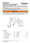
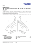
Parts Supplied:
1.
Quick release screen assembly
1 off
8.
Large spacer
2 off
2.
Mounting bracket, left hand
1 off
9.
Small spacer
2 off
3.
Mounting bracket, right hand
1 off
10. Spacer, stainless steel
2 off
4.
Upper mounting
2 off
11.
2 off
5.
Lower mounting
2 off
12. Outer bracket, left hand
1 off
6.
Screw, countersunk head, M8 x 50
2 off
13. Rubber pad, small
2 off
7.
Outer bracket, right hand
1 off
14. Rubber pad, large
2 off
Publication part number A9900430 issue 6, DC 72188
© Triumph Designs Ltd. 2015
1 of 8
Screw, button head, M8 x 50
Warning
This accessory kit is designed for use on
Triumph Bonneville and Bonneville T100 motorcycles only
and should not be fitted to any other manufacturer’s
motorcycle. Fitting this accessory kit to any other
manufacturer’s motorcycle will affect the performance,
stability and handling of the motorcycle. This may affect
the rider’s ability to control the motorcycle and could
cause an accident.
1.
Remove the seat as described in the service manual.
2.
Disconnect the battery, negative (black) lead first.
3.
Remove the headlamp fixings. Support the headlamp
ensuring it does not hang from the wiring harness.
Retain the fixings for reuse.
Warning
Always have Triumph approved parts, accessories and
conversions fitted by a trained technician of an authorised
Triumph dealer. The fitment of parts, accessories and
conversions by a technician who is not of an authorised
Triumph dealer may affect the handling, stability or other
aspects of the motorcycle’s operation which may result in
loss of motorcycle control and an accident.
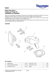
1. Headlamp
2. Fixings
Warning
4.
Throughout this operation, ensure that the motorcycle is
stabilised and adequately supported to prevent risk of
injury from the motorcycle falling.
Warning
A torque wrench of known accurate calibration must be
used when fitting this accessory kit. Failure to tighten any
of the fasteners to the correct torque specification may
result in loss of motorcycle control and an accident.
If fitted, remove the spacer plates from the headlamp
mounting brackets. Retain the spacer plates if the
motorcycle is returned to original condition.
1. Headlamp bracket
2. Spacer, (if fitted)
2 of 8
5.
If fitted, do not remove the original grommets from the
headlamp mounting brackets.
8.
Locate the left and right hand indicator connections in
the headlamp bowl (black and white wires). Mark the
connections to aid identification on re-assembly.
1. Grommet
6.
Remove the headlamp bezel fixings. Retain the fixings
for reuse.
1. Headlamp bowl
2. Indicator connections
9.
Disconnect both indicator connections.
10. Release any straps retaining the indicator wiring to the
headlamp bowl.
1. Headlamp bezel
2. Fixings
7.
Remove the headlamp bezel. Support the headlamp
bezel and lamp, ensure it does not hang from the
headlamp wiring harness.
3 of 8
1. Indicator wiring
2. Strap
11.
Gently pull the indicator wiring, through the grommet,
out of the headlamp bowl.
14. Locate the left hand and right hand mounting brackets
in position, as shown below.
1. Headlamp bowl
2. Indicator wiring
1. Mounting bracket
2. Fork leg
12. Peel off the backing strip from the back of the rubber
pads.
15. Feed the indicator wiring through the mounting
brackets as shown below.
13. Fit the large rubber pads to the smaller half of the left
and right hand mounting brackets and the small
rubber pads to the larger half of the brackets, as shown
below.
1
2
3
1. Mounting bracket
2. Indicator
3. Indicator wiring
T0586_3
1. Large rubber pad
2. Small rubber pad
3. Mounting brackets
4 of 8
16. Fit a countersunk head screw, upper mounting, right
hand outer bracket and large spacer into the right
hand mounting bracket. Do not fully tighten the screw
at this stage.
21.
Position one of the stainless steel spacers, aligning the
holes of all three items as shown below.
1.
2.
3.
4.
17.
1. Mounting bracket
2. Headlamp mounting
3. Stainless steel spacer
Outer bracket
Upper mounting
Countersunk head screw
Large spacer
22. Repeat step 21 for the right hand side.
Repeat steps 14 to 16 for the left hand screen bracket.
Note, the left hand outer bracket must locate correctly
over the ignition barrel, as shown.
23. Refit the headlamp assembly and secure with the
original fixings. Do not fully tighten the fixings at this
stage.
24. Fit a button head screw, lower mounting and small
spacer to the right hand mounting bracket and right
hand outer bracket, as shown. Do not fully tighten the
screw at this stage.
1. Outer bracket
2. Ignition barrel
18. Feed the indicator wiring back through the grommet
into the headlamp bowl.
19. Re-connect the indicators as noted earlier.
20. Refit the headlamp bezel and secure with the original
fixings. Tighten to 3 Nm.
1.
2.
3.
4.
5.
Outer bracket
Mounting bracket
Lower mounting
Button head screw
Small spacer
25. Repeat step 24 for the left hand side.
26. Re-connect the battery, positive (red) lead first.
5 of 8
27. Switch on the ignition and check that the headlamp
and indicators operate correctly. Rectify as necessary.
28. Refit the seat as described in the service manual.
34. Align the screen upper mounting slots with the upper
mountings. With a firm push, fully engage the upper
mountings.
29. Adjust the headlamp beam alignment as described in
the service manual.
30. Tighten the headlamp fixings to 10 Nm.
31.
Visually check that the mounting brackets and outer
brackets are parallel. Re-position the brackets if
necessary, repeating the appropriate steps from 14 to
30, to ensure the mounting brackets and outer
brackets are parallel.
Note:
•
The screen must be temporarily fitted to check
the screen alignment with the headlamp, before
the mounting bracket fixings are fully tightened.
32. Stand astride the front wheel with a firm grip on both
sides of the screen close to the upper mountings.
33. Locate the screen onto the lower mountings. Carefully
rotate the screen over the headlamp, as shown.
1. Screen
2. Upper mountings
35. Ensure the screen locates correctly over the headlamp
and locks in position.
36. To remove the screen, stand astride the front wheel
and firmly grip both sides of the screen close to the
upper mounting.
1. Screen
2. Lower mounting
3. Headlamp
Note:
•
An audible click can be heard when the screen
upper mountings are fully engaged.
1. Screen
2. Upper mounting
37. Pull the screen firmly to disengage the upper
mountings.
6 of 8
38. Carefully rotate the screen away from the headlamp, as
shown below, and lift clear from the lower mounting.
If, after fitment of this accessory kit, you have any doubt
about the performance of any aspect of the motorcycle,
contact an authorised Triumph dealer and do not ride the
motorcycle until the authorised dealer has declared it fit
for use. Riding a motorcycle when there is any doubt as to
any aspect of the performance of the motorcycle may
result in loss of control of the motorcycle leading to an
accident.
Warning
After fitting the quick release screen the motorcycle will
exhibit new handling characteristics. Operate the
motorcycle in a safe area free from traffic to gain familiarity
with any new characteristics. Operation of the motorcycle
when not familiar with any new handling characteristics
may result in loss of motorcycle control and an accident.
1. Screen
2. Lower mounting
3. Headlamp
Note:
•
Warning
During steps 39 to 41 only one screw must be
removed at any time.
39. Remove the left hand side countersunk head screw
and upper mounting. Ensure the spacer and all
brackets remain in position. Apply 2 - 3 drops of
ThreeBond 1305, or equivalent thread locking
compound, to the screw threads. Refit the screw and
upper mounting. Tighten the screw to 22 Nm.
40. Repeat step 39 for the left hand side button head
screw and lower mounting.
41.
Warning
Repeat steps 39 and 40 for the right hand side.
Never attempt to clean the screen while riding the
motorcycle. Removal of the rider’s hands from the
handlebars while riding the motorcycle will diminish the
ability of the rider to maintain control of the motorcycle.
Attempting to clean the screen while riding the motorcycle
may result in loss of control of the motorcycle and an
accident.
Warning
Never ride an accessory equipped motorcycle at speeds
above 80 mph (130 km/h).
42. Repeat steps 32 to 35 to refit the screen.
The presence of accessories will cause changes in the
stability and handling of the motorcycle. Failure to allow
for changes in motorcycle stability may lead to loss of
control or an accident.
Remember that the 80 mph (130 km/h) limit will be
reduced by the fitting of non-approved accessories,
incorrect loading, worn tyres, overall motorcycle condition
and poor road or weather conditions.
7 of 8
Warning
Warning
The quick release screen is not a substitute for a safety
helmet or eye protection. Quick release screens are
designed to provide wind protection and increased riding
comfort. They are not designed to provide protection in
the event of a collision with another vehicle, the road, birds
or any other object. When riding a motorcycle both rider
and passenger must always wear a safety helmet, eye
protection, boots, gloves and trousers (close fitting around
the knees and ankle). Although full protection is not
possible, wearing the correct protective clothing can
reduce the risk of injury when riding.
Warning
The motorcycle must not be operated above the legal
road speed limit except in closed-course conditions.
8 of 8
Only operate this Triumph motorcycle at high speed in
closed-course on road competition or on closed-course
racetracks. High speed operation should only be
attempted by riders who have been instructed in the
techniques necessary for high speed riding and are
familiar with the motorcycle’s characteristics in all
conditions.
High speed operation in any other circumstances is
dangerous and will lead to loss of motorcycle control and
an accident.