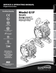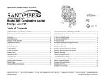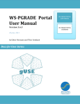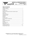
1
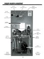
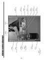
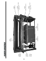
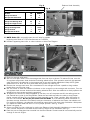
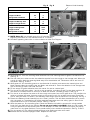
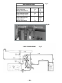
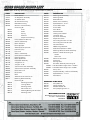
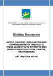
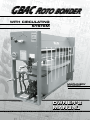
GBAC RROTO
OTO BONDER
BONDER
WITH CIRCULATING
SYSTEM
G
B
MACHINERY
DIVISION
OWNER’S
MANUAL
L to R Unit Shown
--
IMPORTANT FOREWORD
1) To ensure efficiency, the GBAC must be properly maintained. Carefully follow the clean-up procedures outlined in this manual. Should
a valve handle become sluggish or stuck, remove the valve from
the plumbing system, dismantle and clean it in warm water.
2) Check and adjust the air supply every week. (See Maintenance
Section.)
3) The GBAC is designed for use with genuine Duro Dyne waterbased adhesives.
IMPORTANT
Always follow manufacturer's recommendations for proper safety and
handling procedures for all materials used in conjunction with this
machine as outlined in Manufacturer's Safety Data Sheet (MSDS)
for each product.
TABLE OF CONTENTS
IMPORTANT FOREWORD
PARTS LOCATION
OPERATION
CLEAN-UP
MAINTENANCE
WIRING DIAGRAM
ELECTRIC SYSTEM - SERVICING
CIRCULATION SYSTEM - SERVICING
PARTS LISTING
--
2
3-5
6
7-8
8
8
9
10-11
12
PUMP PARTS LOCATION
39172
Clean Up Switch
39237
Adjustment Knob
39238
Adjustment Handle
Casting
39109
Power Light
17309
Power Switch
39239
Valve Chart
39236
Metering Wheel
17377
Air Regulator
39197
Multi-Port Valve
(only)
39169
Valve 1-2
Assembly
1
3
4
39032
Valve 3-4
Assembly
2
39247
GBAC Aro Pump
39252
Complete
Plumbing Assembly
(not shown)
39019
Rebuild Kit for
Aro Pump
(not shown)
--
--
39201
Transmission Gear
(not shown)
39118
Cord
39094
Motor
39220
R to L Reducer
(not shown)
39258
L to R Reducer
(shown)
39202
Transmission Sprocket
39205
Drive Chain
MOTOR PARTS LOCATION
39206
Pinion Gear
39207
Rack
39208
Adhesive Chain
39098
Adhesive Sprocket
39262
Pillow Block
39211
Metering Base Assembly
39209
Metering Bracket Only
39210
Locking Wheel
39098
Drive Sprocket
--
39179
Trough
(L to R)
39178
Trough
(R to L)
39228
Adhesive
Roller
PARTS LOCATION
39243
Storage Tank
39231
Top Cover
39242
Storage Tank Cover
39245
Exit Finger Covers (clear)
(set of 10)
39244
Exit Rack Assembly
39246
Exit Rack Finger Tips (yellow)
(set of 10)
39227
Drive Roller
Selector Knob Assembly
Fig. A
VALVE FUNCTION CHART
Fig. C
TURN SPECIFIED VALVE HANDLE TO APPROPRIATE POSITION
TO FILL:
Trough from Drum
Storage Tank from Drum
UP
2-4
4
DOWN
3
2-3
CIRCULATE:
Trough from Storage Tank
Trough to Trough (in-out)
2-3
2
4
3-4
TO EMPTY:
Trough to Storage Tank
Trough to Drum
Storage Tank to Drum
1
1-3
1-2-3-4
2·3-4
2
1) NOTE: Valve #5 is a normally open shut-off valve for models
beginning with Serial #7132 (manufactured on10-28-80)
2) Numbers appearing here refer to valve numbers on Valve Flow Diagram.
Fig. B
Clean Position
Fig. D
OPERATION
1) Open the storage tank cover.
2) Set the multi-port valves to fill the storage tank from the drum as shown. To reduce fill time, turn the
air regulator adjustment knob clockwise increasing adhesive flow. (This operation need only be repeated
when the level of the adhesive in the storage tank is low and is being replenished. Keep the 55 gallon
adhesive drum for later use as a water bath during clean-up.) See Fig. B.
3) Remove the storage tank cover. Stir the adhesive in the storage tank with a paddle or long wooden
handle after removing the cover.
4) Set the valves so that the adhesive circulates to the trough from the storage tank as shown. Turn the
air regulator knob counter clockwise (decreasing adhesive flow). Allow the adhesive to slowly spillover the
spillgate into the storage tank during operation.
5) To regulate the amount of adhesive applied to the liner, turn off the power and lift the safety guard on
the material entry side of the Roto Bonder. Raise the feed table and allow the table to drop perpendicular toward the floor. Turn the Selector Knob Assembly to the “Clean” position. With the power on,
look into the machine. Do not put your hands into the GBAC. Turn the Metering Wheel (clockwise to
decrease-counter clockwise to increase) to adjust the amount of adhesive that coats the adhesive roll.
For maximum efficiency, the adhesive roll should be coated with a thin even coat of adhesive. With power
off, replace the feed table and return it to its proper position. See Fig. C and D.
6) Switch the power on.
7) Adjust the GBAC for liner thickness by moving the Selector Knob Assembly [clockwise to increase (thicker
liner), counter clockwise to decrease (thinner liner)] to adjust the roll clearances. See Fig C.
8) Feed the pre-cut fiberglass liner material into the Roto Bonder. Coated material is automatically carried
through to the exit fingers.
--
Fig. A
Fig. C
Selector Knob Assembly
VALVE FUNCTION CHART
TURN SPECIFIED VALVE HANDLE TO APPROPRIATE POSITION
TO FILL:
Trough from Drum
Storage Tank from Drum
UP
2-4
4
DOWN
3
2-3
CIRCULATE:
Trough from Storage Tank
Trough to Trough (in-out)
2-3
2
4
3-4
TO EMPTY:
Trough to Storage Tank
Trough to Drum
Storage Tank to Drum
1
1-3
1-2-3-4
2·3-4
2
1) NOTE: Valve #5: is a normally open shut-off valve for models
beginning with Serial #7132 (manufactured on 10-28-80)
2) Numbers appearing here refer to valve numbers on Valve Flow Diagram.
Fig. B
Clean Position
Fig. D
Clean-up
1) With power on, turn the metering wheel clockwise until the metering blade is against the adhesive roll.
See Fig. D.
2) Set the multi-port valves so that the adhesive empties from the trough to the storage tank. When the
trough is empty, back the metering blade away from the adhesive roll. Disconnect the air and turn off
the power. See Fig. A and D.
3) With power off, lift the safety guards on the feed side of machine, and remove the metering bar and
blade. Sponge clean the metering bar and blade, and reinstall it. Cover the adhesive in the storage tank
with a thin film of water, and cover the tank.
4) Fill the empty 55 gallon adhesive drum with water for use as a water bath.
5) Turn the air on and place valves 1 and 4 to the up position, and valves 2 and 3 to the down position. Allow water to circulate (drum to drum) for at least (2) minutes. Proceed to Step 6. See Fig. A.
6) Turn the air on and adjust the valves to fill the trough with water from the 55 gallon drum. Then readjust the
valves to circulate the water from the trough to the trough (in-out), for at least five minutes. Disconnect
the air. Allow the water to remain in the stainless steel trough while the machine is not operating. See Fig. A
7) Rotate the Selector Knob Assembly into the “Clean” position. This will allow the adhesive roll to rotate
with the guard up. The adhesive roll will be rendered inoperative when the safety guard is lifted if the
adjustment lever is not in the clean position. See Fig. C and D.
8) With the power on, lift the safety guard. Clean the adhesive roll while it rotates with a long handled
brush from the feed side of the machine. Do not put your hands in the GBAC. When the roll is clean, be
sure you reposition the adjustment lever. Do not attempt to clean the adhesive roll unless the adjustment lever is in the clean position. Do not render safety micro-switches inoperative. See Fig. C and D.
9) Turn the power off. (The metering blade will have to be readjusted when next used.)
10)Remove the exit rack and sponge it clean. Replace the exit rack.
--
EXTENDED CLEAN-UP
NOTE: If the machine is to be idle for several days there are additional clean-up procedures which must
be followed.
1) With power off remove the exit rack and metering bar. With a long handled brush wipe down the trough.
At this time the trough should still contain water.
2) Cover the 55 gallon drum of water. Turn the air on and empty the adhesive from the storage tank to the
55 gallon drum. Cover the adhesive in the 55 gallon drum with a thin coat of water and cap the drum.
See Fig. A
3) Set the multi-port valves so that the water empties from the trough to the storage tank. See Fig. A and B
4) With the power off remove the feed table and tank cover. Set the multi-port valves to fill the storage tank
from a convenient water bath, and with a long handled brush wipe the side of the storage tank. See Fig. A
5) Set the multi-port valves so that the water empties from the storage tank to a convenient water container. See Fig. A
6) Disconnect the air and power. Wipe the adhesive roll dry and return the feed table, exit rack, and metering
bar to their proper position.
MAINTENANCE
1) Periodically grease the end bearings on the adhesive roll as well as the metering bar gearing.
2) The metering bar wiper blade can be removed and rotated 180° (end over end) as the blade shows wear.
AIR SUPPLY UNIT
1) To provide uninterrupted service, the air regulator assembly must be kept clean. Turn the drain valve clockwise to drain off any filter bowl accumulation before it becomes full. A visible coating of dirt or condensate
on the filter element or erratic operation indicates cleaning is necessary. Wash the filter element and
the regulator, in denatured alcohol and blow them out with compressed air. Clean the Filter Bowl With
Household Soap Only.
2) Check for leaks in all air hoses.
3) Check and adjust the air pressure to 80 psi minimum. When reducing regulator pressure, pull the knob
upward and turn the knob counter-clockwise. Cycle the machine before reading the gauge. To increase air
pressure repeat the procedure turning the knob clockwise.
WIRING DIAGRAM
Fig. E
--
ELECTRIC SYSTEM SERVICING
It is necessary to use a voltmeter and an ohmmeter
to perform the simple servicing procedures.
Follow the instructions below for reading resistance and voltage.
MEASURING RESISTANCE (OHMMETER)
1) Disconnect the power supply.
MEASURING AC VOLTAGES
(VOLTMETER)
250
2) Set the ohmmeter at x1000
scale and keep it there for
all resistance reading.
250
1) Set the voltmeter at
ACV
the nearest
scale above
(never below) the voltage
you wish to read.
3) Touch the two probes
together and “zero” the
ohmmeter.
1
1
110 V
2
1
110 V 110 V
110 V
2
3
ACV
ELECTRICAL SERVICING
1
3
ACV
1
ACV
110 V
250
ACV
1) Check the power supply for 110 volts.
2) CAUTION: This troubleshooting step requires
bypassing the safety switches. Be extremely
careful to keep hands and clothing away from
any moving parts or electrical connections.
Remove the top cover. Remove the screws
retaining the inner panel with the guard interlock attached. Let this panel hang. Depress
each microswitch placing a shim between the
microswitch button and the flange the button
protrudes through. With power on, read voltage
across 1 and 2 on terminal strip.
250
If the voltmeter reads: 110 volts, proceed to
Step 3.
ACV
If the voltmeter reads: “0” V: the problem is
either broken wires from the power supply to the
power switch or a defective power switch.
110 V
ACV
110 V
If the power switch is on and the rolls do not turn,
4
follow the procedure outlined below.
1
1
ACV
1
ACV guard interlock
either a faulty or4 misadjusted
ACV
or a broken wire from the terminal strip to the
guard interlock. (Trace the wires from the
terminal strip to the guard interlock.)
1
110 V
1
110 V
2
ACV
3
ACV
250
ACV
4) With1 the power on,
110 V read the voltage across 1
and 4 on the terminal strip.
ACV reads: 110 volts, proceed to
If the 1voltmeter
1
4
110 V
110 V
Step 5.
2
If the voltmeter reads: “0”
V: the problem is
3
ACV
ACV
either a faulty or
misadjusted guard interlock
or
a broken wire from terminal strip to the guard interlock. (Trace the wires to the guard interlock.)
1
110 V
110 V
ACV
4
2
ACV
3
ACV
1
110 V
3) With the power on, read the voltage across
1
and 3 on the terminal strip.
ACV
If the voltmeter reads: 1104 volts, proceed
to
Step 4.
If the voltmeter reads: “0” V: the problem is
--
5) Replace the panel and the cover. Remove the
motor side cover. With the power on, check
whether the motor is turning or not. If the motor
does turn, check that the keys and set screws
in the sprocket are in position and tight. If the
motor does not turn, check that the reducer is
not bound up - replace the motor.
Fig. A
VALVE FUNCTION CHART
TURN SPECIFIED VALVE HANDLE TO APPROPRIATE POSITION
TO FILL:
Trough from Drum
Storage Tank from Drum
UP
2-4
4
DOWN
3
2-3
CIRCULATE:
Trough from Storage Tank
Trough to Trough (in-out)
2-3
2
4
3-4
TO EMPTY:
Trough to Storage Tank
Trough to Drum
Storage Tank to Drum
1
1-3
1-2-3-4
2·3-4
2
Fig. B
VALVE FLOW DIAGRAM
- 10 -
Fig. F
CIRCULATION SYSTEM SERVICING
The air is on but the adhesive is not circulating through the plumbing.
NOTE: Never force a valve handle. If a valve handle sticks, remove the valve and soak it in warm water.
1) Check the valve setting against the function chart to insure that the valves are set properly. If the valves
are set properly, proceed to Step 2.
2) Check that number 2 valve is either in the up or down position. The circulation system will not work unless
number 2 valve is in either position. Then proceed to Step 3.
3) Check that the air-regulator unit is functioning according to the maintenance section of the Operating Instructions.
4) Disconnect the air line that leads from the regulator to the pump. With the air line disconnected, check
the air supply. If there is no air leading into the pump, proceed to Step 5. If there proves to be a good air
supply, reconnect the air line and proceed to Step 6.
5) Disconnect the air line leading to the air regulator and check the air supply. If there is a good air supply to the regulator, replace the regulator. If there is no air supply to the regulator, the problem is independent of the GBAC.
6) Fill a bucket with warm water. Place the GBAC input hose in the warm water and set the valves to fill the
trough from the drum. Activate the pump. If the water begins to pump into the trough, deactivate the
pump immediately and proceed to Step 8. If no water pumps to the trough, proceed to Step 7.
7) Fill a bucket with warm water. Place the GBAC input hose in the warm water and set the valves to fill the storage
tank from the drum, Activate the pump with air. If the water begins to pump into the storage tank, deactivate
the pump immediately and proceed to Step 8. If the water does not circulate, proceed to Step 9.
8) Remove the bucket of warm water and set the multi-port valves to circulate the adhesive from the drum
to the trough. If the adhesive will not circulate, proceed to Step 9.
9) Set the multi-port valves so that adhesive circulates from the storage tank to the trough. Activate the
pump and observe whether adhesive is flowing into the trough. If there is an adhesive flow, proceed to
Step 12. If there is no adhesive flow, proceed to Step 10.
10)Disassemble the plastic union located beneath valve 2. Set the multi-port valves so that glue circulates
from the storage tank to the trough. If adhesive is pumped from the union, disconnect the air and replace
the valve assembly 1 and 2.
Note: It is important that all surfaces on the valves and the unions be free of glue residue before reassembly.
If the glue is not pumped out from the union, disconnect the air, reassemble the union and proceed to Step
11 .
11)Set the multi-port valves so that the adhesive empties from the tank to the drum. Activate the pump. If the
adhesive exits the machine from the out port, replace valves number 3 and 4. (Order an assembly.) Close
valve number 5 if supplied, before disassembling valve number 3 and number 4. After replacing valve number
3 and number 4, open valve number 5. If the adhesive is not pumped out the exhaust port, proceed to Step
12.
12)Set the multi-port valves so that the trough is filled from the drum. Activate the pump. If adhesive is
pumped into the trough, replace valve assembly number 1 and number 2. If adhesive does not pump into
the trough, proceed to the pump service manual.
- 11 -
GBAC SPARE PARTS LIST
NOTE: When ordering spare parts include serial number of machine.
G
B
A
C
ITEM#
DESCRIPTION
17309
Power Switch
17377
Air Regulator Assembly
39001
Air Sleeve Valve
39003
Street Elbow Fitting
39004
Male Elbow Fitting
39006
Selector Knob Assembly
Consisting Of:
39237
Knob
39007
Shaft
39008
Spring
39009
Retainer
39238
Adjustment Casting
39019
Pump rebuild kit ARO only
39032
Valve 3-4 Assembly
39094
Motor (Electric)
39098
Drive Sprocket
39098
Adhesive Drive Sprocket
39109
Indicator Lamp
39118
Line Cord
39169
Valve 1-2 Assembly
39172
Guard Interlock (Switch)
39172
Clean Up Switch
39176
Motor Side Cover
39177
Feed Table Assembly
39178
Trough (R to L)
39179
Trough (L to R)
39201
Transmission Gear Assembly
39202
Transmission Sprocket Assembly
39205
Drive Chain Link
39206
Pinion Gear
39207
Rack
39208
Adhesive Drive Chain & Link
39211
Metering Base Assembly
Consisting Of:
39209
Metering Bracket
39210
Locking Wheel
39212
Metering Shaft
39216
Mitre Gear (Pr.)
39217
Metering Bushing 1/2 ID (3 set)
39218
Metering Collar
ITEM#
DESCRIPTION
39213
Metering Bar Assembly
39214
Metering Blade
39215
Blade Retainer
39219
Sleeve Joint Assembly
39220
Speed Reducer - R to L
39225
Pinion Shaft Collar
39226
Pinion Shaft
39227
Drive Roller
39228
Adhesive Roller
39229
Leveling Feet (4/Set)
39230
Universal Joint
39231
Top Cover Assembly
39237
Adjustment Knob
39260
Connecting Rod (R-L 57 1/2")
39261 Connecting Rod (L-R 59 1/2")
39271
Flat Pillow Block
39272
GBAC Trough Strainer
39233
Side Panel (Operator's Side)
39236
Metering Wheel & Handle Assembly
39238
Selector Handle Consisting Of:
Handle
Setscrew
39239
Valve Function Chart
39242
Tank Cover
39243
Storage Tank
39244
Exit Rack Assembly Consisting Of:
39245 - 1 Set Rack Plastic Finger Covers (10/Set)
39246 - 1 Set Rack Plastic Finger Tips (10/Set)
39247
Pump ( Aro )
39252
Complete Plumbing 1-2 and 3-4 Assembly
39258
Speed Reducer - L to R
39262
Pillow Block
SANDPIPER
39015
39016
39017
39018
PUMP PARTS
Pump Balls (4)
Flange Gasket (4)
Manifold Gasket (2)
Pump Diaphragm Set (1)
MACHINERY DIVISION
© 2008 Duro Dyne Corporation
Printed in USA 09/2008
BI039405
- 12 -
®