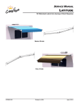
1
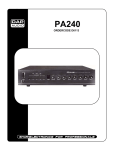
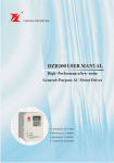
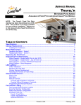
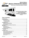
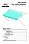
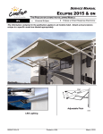
SERVICE MANUAL LATITUDE 12V Motorized Lateral Arm Awning w/ Direct Response SINGLE STAGE DUAL STAGE 070005-301r1 Printed in USA October, 2014 PROPRIETARY STATEMENT The Latitude Awning is a product of Carefree of Colorado, located in Broomfield, Colorado, USA. The information contained in or disclosed in this document is considered proprietary to Carefree of Colorado. Every effort has been made to ensure that the information presented in the document is accurate and complete. However, Carefree of Colorado assumes no liability for errors or for any damages that result from the use of this document. The information contained in this manual pertains to the current configuration of the models listed on the title page. Earlier model configurations may differ from the information given. Carefree of Colorado reserves the right to cancel, change, alter or add any parts and assemblies, described in this manual, without prior notice. Carefree of Colorado agrees to allow the reproduction of this document for use with Carefree of Colorado products only. Any other reproduction or translation of this document in whole or part is strictly prohibited without prior written approval from Carefree of Colorado. SAFETY INFORMATION WARNING A WARNING INDICATES A POTENTIALLY HAZARDOUS SITUATION WHICH, IF NOT AVOIDED, COULD RESULT IN DEATH OR SERIOUS INJURY AND/OR MAJOR PROPERTY DAMAGE. CAUTION A caution indicates a potentially hazardous situation that may cause minor to moderate personal injury and/or property damage. It may also be used to alert against unsafe practices. NOTE: A note indicates further information about a product, part, or step. Tip: A tip provides helpful suggestions. Safety Notes: To avoid shock hazard and/or accidental system shorting, always disconnect battery or power source before working on or around the electrical system. Always wear appropriate safety equipment (i.e. goggles). Awnings have significant weight. Always use appropriate lifting devices and/or helpers when lifting or holding heavy objects. When using fasteners, use care to not over tighten. Soft materials such as fiberglass and aluminum can be "stripped out" and lose the ability to grip and hold. Reference Publications located @ www.carefreeofcolorado.com: 070005-001 Installation Manual 070005-201 Owner's Manual 070005-301 Service Manual Carefree of Colorado 070005-301r1 2145 W. 6th Avenue Broomfield, CO 80020 a Scott Fetzer company October, 2014 TABLE OF CONTENTS Standard System Adjustments .................................................................................................... 1 Adjusting the Arm Position...................................................................................................................... 1 Adjusting the Pitch .................................................................................................................................. 1 Canopy Replacement .................................................................................................................... 2 Removing the Head Covers .......................................................................................................... 4 Removing the Covers .......................................................................................................................... 4 Attaching the Covers ........................................................................................................................... 4 Arm Replacement .......................................................................................................................... 5 Gas Spring Replacement .............................................................................................................. 6 RH (Motor) Arm Spring ........................................................................................................................... 6 LH (Idler) Arm Spring .............................................................................................................................. 6 Replacing the Mounting Plate ...................................................................................................... 7 Motor/Gearbox Replacement ........................................................................................................ 8 Sensor/Control Module Replacement .......................................................................................... 9 LED Lighting ................................................................................................................................ 10 Switch Installation ................................................................................................................................. 10 LED Strip Replacement ........................................................................................................................ 11 LED Harness Replacement .................................................................................................................. 12 Wiring Diagrams .......................................................................................................................... 13 Switch and Control Module ............................................................................................................... 13 LED Lighting...................................................................................................................................... 13 Standard Maintenance ................................................................................................................ 14 Fabric Care ........................................................................................................................................... 14 Mildew ............................................................................................................................................... 14 Pooling .............................................................................................................................................. 14 Hardware Maintenance ..................................................................................................................... 14 Motor Maintenance ............................................................................................................................... 14 Part Number Listing .................................................................................................................... 15 Part Number/Serial Number Location ................................................................................................... 15 Part Number Configuration ................................................................................................................... 15 Illustrated Parts List .............................................................................................................................. 16 Latitude – Single Stage ..................................................................................................................... 16 Latitude – Dual Stage........................................................................................................................ 18 070005-301r1 Printed in USA October, 2014 PRODUCT OVERVIEW The Latitude Awning is a state of the art lateral arm awning. Each unit is equipped with lateral support arms. No vertical arms interfere with coach sidewalls, custom graphics or equipment mounted on the sidewalls. Fully retractable and self-storing; Available in two configurations: single stage or dual stage; The awning motor operates on standard 12VDC (range 10VDC to 14VDC); Single touch operation for extend and retract; Direct Response is standard; LED lights standard, mounted in roller tube; SPECIFICATIONS Single Stage 10' 4" – 20' [3.15m – 6.1m] Length Dual Stage 10' 4" – 18' [3.15m – 5.49m] Lateral Spring Arms Support: Power: 10VDC–14VDC Circuit Rating: 15 amp Motor: (motor is mounted in RH roller tube head) Motor and controls are routed and hardwired into the vehicle’s 12V system Power Source: Carefree Direct Response Controls: Hardware: White or Black Color: Fabric: Heavy Duty Vinyl with Weatherguard or FLXGuard (refer to sales literature for colors and options) 10' 4" 12' 14' 16' 18' 20' Weight: Single Stage 45.5 lbs. 48.3 lbs. 51.7 lbs. 55.0 lbs. 58.3 lbs. 61.6 lbs. Dual Stage 52.1 lbs. 55.9 lbs. 60.4 lbs. 65.0 lbs. 69.6 lbs. n/a Awning Length + 3.9" Awning Length 2.7" 1.2" 6.1" 7" 12.75" 12.75" 5.6" 5.6" FL002 Original Mounting Plate Configuration Awning Length + 2.6" Awning Length 1.3" 1.3" 6.1" 7" 12.25" 13.75" 5.7" 5.7" FL002b Current Mounting Plate Configuartion 070005-301r1 October, 2014 Carefree of Colorado Service Manual LATITUDE STANDARD SYSTEM ADJUSTMENTS ADJUSTING THE ARM POSITION For the awning to operate and close correctly, the arms must be parallel to the roller tube. If the arm sags, the arm position can be adjusted to bring the arm parallel. 1. Open the awning 2"-3" to access the adjustment screws located on the side of the arm knuckle at the wall. Adjustment Screws 2. Loosen the upper screw (counterclockwise). 3. Tighten (clockwise) the lower screw to raise the arm elbow. Adjust Arm to be Parallel to Roller Tube Raise FL013 NOTE: Make adjustments in quarter turn increments. Tip: Lift the arm at the elbow while tightening the lower screw. 4. Repeat steps 2 and 3 until the arm is parallel with the roller tube. 5. Tighten the upper screw. ADJUSTING THE PITCH The awning pitch can be adjusted. It is strongly recommended that adjustments be made in small increments to achieve the desired setting. This procedure works best with 2 people. One person to lift the roller tube to relieve the weight and one person to make the adjustments. 1. Open the awning. Locking Screw Locking Screw 2. Loosen the locking screw at the top of the knuckle. 3. To raise the pitch: Turn the lower adjustment screw clockwise. 4. To lower the pitch: Turn the lower adjustment screw counterclockwise. 5. Tighten the locking screws when the desired pitch is achieved. Lower Raise Adjustment Screw Lower Raise Adjustment Screw FL009a Important Note: After the initial installation and the awning is opened, the awning may settle. This is normal. Check that the locking screws on the knuckle are snug. 070005-301r1 1 LATITUDE Service Manual Carefree of Colorado CANOPY REPLACEMENT Spring Arms 1. Extend the awning completely. 2. Firmly tie the elbows of the spring arms together. Use a minimum 1/2" rope - do not use bungee cords. When tying the rope, use a non-slip knot such as a square knot or equivalent. CAUTION FAILURE TO SECURE THE ARMS WILL ALLOW THE SPRING ARMS TO EXTEND POSSIBLY CAUSING PERSONAL INJURY AND DAMAGE TO THE AWNING. Firmly Tie Elbows Together Retaining Screw and Washer Align Fabric Slot with Cutout on Idler Head 3. Over extend the awning to align the fabric slot with the cutout on the idler side. This will cause slack in the fabric. 4. Disconnect Power. CAUTION When the power is on, the direct response system is active. Movement during this procedure can cause the awning to attempt to close unexpectedly. 5. At the roller tube: 5.1. Remove the fabric retaining screws and plastic washers (quantity of 2 ea). 5.2. On the motor side, remove the split grommet from the roller tube. Carefully pull the wires and connectors out of the tube and disconnect. 6. At the awning rail, cut the LED harness close to the canopy. Clamp the harness going into the vehicle to prevent it from falling in the wall. LED Harness Retaining Screw and Washer Canopy Grommet Harness 7. For canopies with QuicKonnect: #6 x 3/8" 7.1. Remove the fabric retaining screws from the Awning Rail Screw (x4) QuicKonnect (a & b). (b) (c) Fabric (a) 7.2. Remove one retaining screw from the awning rail (c). 7.3. Slide the QuicKonnect from the awning rail and canopy. QuicKonnect 7.4. Slide the canopy out of the roller tube. 7.5. Slide the new canopy into the roller tube and center. 7.6. At the reinforcements in the canopy, secure the fabric Awning Rail to the roller tube with the retaining screws and wahsers removed previously. Fabric QuicKonnect 7.7. Slip the fabric funnel onto the QuicKonnect. Funnel 7.8. While holding the fabric, simultaneously slide the FL016 QuicKonnect into the awning rail and over the canopy. 7.9. Remove the funnel from the QuicKonnect. 7.10. Place one (1) #6 x 3/8" screw (c) through the awning rail outside the end of the QuicKonnect (not through the QuicKonnect). 8. For canopies without QuicKonnect: 8.1. Remove the fabric retaining screws from the awning rail. 8.2. Slide the canopy out of the roller tube and awning rail. 8.3. Slide the new canopy into the roller tube and awning rail and center in the roller tube. 8.4. At the reinforcements in the canopy, secure the fabric to the roller tube with the retaining screws removed previously. 2 070005-301r1 Carefree of Colorado Service Manual LATITUDE 9. While firmly pressing the roller tube, remove the arm ties. Slowly allow the roller tube and arms to extend. 10. Restore power. 11. Retract the awning and check that the canopy is rolling up squarely onto the roller tube. Adjust as necessary. 12. Place one (1) #6 x 3/8" screw (a) through the QuicKonnect (or awning rail if the QuicKonnect is not used), fabric and polyrod approximately 1" in from the fabric edge 13. On the opposite side, pull the fabric tight then place one (1) #6 x 3/8" screw (b) through the QuicKonnect (or awning rail if the QuicKonnect is not used), fabric and polyrod approximately 1" in from the fabric edge. 14. Connect the LED harness: 14.1. At the roller tube, connect the canopy harness connector and LED connector. Then carefully push the connectors into the roller tube. 14.2. Place the split grommet over the canopy harness and press the grommet into the hole of the roller tube. 14.3. At the vehicle wall, route the new canopy harness through the wall to the switch. Tip: Tie the new harness to the old harness that was cut previously. Use the old harness to pull the new harness through the wall to the desired location. 14.4. At the vehicle wall, provide some slack between the canopy and wall. Seal the wall entrance hole and harness with a quality silicone sealant. 14.5. Connect the new harness to the switch. Two (2) .187, 18-24 awg female disconnects are provided if connecting to a switch. 14.6. Alternate method: At the wall, splice the new harness to the existing harness using 24 awg butt connectors. Push the connectors into the vehicle wall. Seal the wall entrance hole and wires with a quality silicone sealant. NOTE: Be sure to allow enough harness from the canopy to provide some slack for the harness and adequate length for the connectors to be pushed inside the wall before sealing the hole and harness with a quality silicone sealant. 070005-301r1 3 LATITUDE Service Manual Carefree of Colorado REMOVING THE HEAD COVERS These instructions are for removing the head covers for service or replacement. The illustration shows the motor head covers. The instructions apply to both the motor and idler head. NOTE: If replacing the covers: To ensure that the covers properly match up and latch together always replace both the front and rear cover. Replacement kits include both the front and rear covers and attaching hardware. 1. Extend the awning to access the screws in the back cover of the head assembly. 2. Disconnect power. CAUTION WHEN THE POWER IS ON, THE DIRECT RESPONSE SYSTEM IS ACTIVE. MOVEMENTS DURING THIS PROCEDURE CAN CAUSE THE AWNING TO CLOSE UNEXPECTEDLY. Removing the Covers 3. Remove the front cover. The cover snaps onto the Slide Module Out rear cover. To remove, press the bottom of the rear cover until the front cover releases then rotate and lift the front cover off. 4. For the motor side: Slide the sensor module out of the rear cover. It is not necessary to disconnect the wires. Carefully allow the module to hang down. 5. Remove the screws and bumper from the rear cover and remove the rear cover. Attaching the Covers Front Cover Rear Cover 6. Attach the rear cover. 7. For the motor side: Slide the sensor module into the rear cover. Tuck the wires inside the cover. Press Up On Rear Cover to Release Front Cover FL029 8. Snap the front cover onto the rear cover. Hang the cover on the top and swing down until it clicks. 4 070005-301r1 Carefree of Colorado Service Manual LATITUDE ARM REPLACEMENT These procedures apply to both the left and right arms. Differences are noted where required. WARNING THE ARM IS UNDER TENSION TO OPEN. USE EXTREME CARE TO FIRMLY HOLD THE ARMS DURING ASSEMBLY AND DISASSEMBLY TO AVOID ANY SUDDEN OR UNEXPECTED MOVEMENT BY THE ARM. SERIOUS PERSONAL INJURY AND/OR PROPERTY DAMAGE COULD OCCUR. CAUTION When detached, do not allow the roller tube and/or middle rail to drop toward the ground. the twisting motion can damage the opposite arm and awning. Use a scaffold or similar device to support the roller tube and middle rail. Glide 1. Over extend the awning. 2. DISCONNECT POWER. Retaining Screw Middle Rail 3. For Two-Stage Latitude: Loosen the retaining screw in Elbow Pin the glide above the arm elbow. Lift the middle rail off the elbow pin. Provide support for the middle rail. 4. For the motor side arm: Carefully pull the control cable from the slot at the top of the arm channels. It is not necessary to disconnect the cable from the motor or wall. Middle Rail 5. At the roller tube: 5.1. Remove the front cover. The cover snaps onto the rear cover. To remove, press the bottom of the rear cover to Control Cable release the front cover. 5.2. Remove the E-Clip that holds the rotation pin. 5.3. Provide support for the roller tube. Front 5.4. Firmly hold the arm and remove the rotation pin. Pull Cover E-Clip the arm out and allow the arm to extend out below the Rotation roller tube. Support the arm. Pin Roller Tube 6. At the wall connection: Control 6.1. Loosen the setscrew and remove the rotation pin. Cable 6.2. Pull the arm from the knuckle and set aside. 7. Using two people firmly hold the new arm assembly and remove the shipping ties. Allow the arm to slowly open to its maximum extension. CAUTION When the arm is closed, it can open Rotation Set Screw with significant force. Use care when opening. Pin Vehicle Wall FL023 8. Lift the new arm and attach to the wall knuckle with the rotation pin and set screw removed previously. Ensure that the groove in the pin is in line with the screw hole. 9. At the roller tube: 9.1. Fold the arm as necessary and align the arm with the mounting holes. 9.2. Insert the rotation pin. Ensure that the pin is oriented with the groove down. 9.3. Secure the pin with a new e-clip between the arm knuckle and lower attach bracket ear. Ensure that the clip is in the groove of the pin. 9.4. Attach the front cover. 10. For the motor side arm: Carefully press the control cable into the slot at the top of the arm channels. Allow some slack at the joints and elbows to allow the cable to flex when the awning is operated. 11. For Two-Stage Latitude: Press the middle rail glide onto the elbow pin. Tighten the securing screw loosened previously. 12. To align the arm. Refer to "Adjusting the Arm Position" on page 1. 13. To adjust the arm pitch. Refer to "Adjusting the Pitch" on page 1. 070005-301r1 5 LATITUDE Service Manual Carefree of Colorado GAS SPRING REPLACEMENT WARNING THE GAS SPRING CLEVISES MUST BE ORIENTED AND INSTALLED AS SHOWN. FAILURE TO ORIENT THE CLEVISES CORRECTLY CAN CAUSE THE ARMS TO NOT FUNCTION CORRECTLY. CAUTION When detaching the roller tube, do not allow the roller tube to drop toward the ground. the twisting motion can damage the opposite arm. Use a scaffold to support the roller tube. 1. Fully extend the awning. 2. DISCONNECT POWER. RH (MOTOR) ARM SPRING 1. Remove the front cover. To remove, press the bottom of the rear cover to release the front cover. Inner Groove 2. Remove the E-clip from the roller tube shaft. Roller Tube 3. While firmly holding the arm, slide the motor head off the roller tube shaft. Provide support for the roller tube. 4. Slowly allow the arm to extend fully. Provide support for E-Clip the end of the arm. Front 5. Remove the old spring in the following order: Cover 5.1. Unclip the cylinder clevis from the upper bracket. 5.2. Unhook the rod clevis from the lower bracket. 6. Install the new spring in the following order: Upper 6.1. Hook the rod clevis around the lower bracket post. Bracket Clevises Must Be Oriented and Installed As Shown 6.2. Clip the cylinder clevis onto the upper bracket post. 7. Fold the arm to align the roller tube shaft with the motor head. It may be necessary to twist the roller tube to align the flats of the shaft with the motor hole. Lower 8. Secure the shaft with a new e-clip. The e-clip goes in Remove 1st Bracket the inner groove of the roller tube shaft. Attach 2nd 9. Reattach the front cover. LH (IDLER) ARM SPRING Motor Side Outer Groove Remove 2nd Attach 1st 1. Remove the front cover. To remove, press the bottom of the rear cover to release the front cover. Roller Tube 2. Remove the e-clip (and press nuts and washers if installed) from the roller tube shaft. Front 3. While firmly holding the arm, slide the idler head off the Cover E-Clip roller tube shaft. Provide support for the roller tube. Replaces Washers, 4. Slowly allow the arm to extend fully. Provide support for Nuts and E-Clip the end of the arm. 5. Remove the old spring in the following order: Upper 5.1. Unclip the rod clevis from the lower bracket. Clevises Must Be Oriented Bracket 5.2. Unhook the cylinder clevis from the upper bracket. and Installed As Shown 6. Install the new spring in the following order: 6.1. Hook the cylinder clevis around the upper bracket post. 6.2. Clip the rod clevis onto the lower bracket post. nd Lower 7. Fold the arm to align the roller tube shaft with the idler head. Remove 2 Bracket st Attach 1 8. Secure the shaft with a new E-clip. The e-clip goes in the outer groove of the roller tube shaft. Remove 1st 9. Reattach the front cover. Attach 2nd FL021 Idler Side 6 070005-301r1 Carefree of Colorado Service Manual LATITUDE REPLACING THE MOUNTING PLATE This procedure requires two people. The illustrations show the RH plate. The procedure is the same for the LH plate. Tie Arm Together 4" 1. Open the awning 18"-24". This is to allow adequate room for tools and access to the mounting plate. 2. Disconnect power. 3. Do not remove the bottom inner screw and the outer upper screw marked with * in the illustration. Remove Control Cable the rest of the plate fasteners and set aside. Set Screw 4. On the side being repaired: 4.1. Collapse the arm. Leave a space between the arm and plate to access the set screw in later steps. 4.2. Securely tie the arm channels together with zip ties. The ties should be close to the head. 5. Have a second person hold and support the roller tube and arm at the arm elbow. Mounting Plate Rotation Pin Fasteners (x9) * Remove these fasteners last from old plate; Attach these fasteners first with new plate FL026 6. For the motor side mounting plate: CAUTION If replacing the plate on the motor side, use care to not pull or damage the cable. 6.1. If the motor cable is routed into the vehicle outside of the plate: Partially remove the wire from the top of the arm channel to provide adequate slack to move the cable out of the way. 6.2. If the motor cable and LED harness are routed through a hole in the plate: Pull some slack cable out of the wall and cut the wires. It will be necessary to splice the wires together after the new plate is installed. 7. Remove the two remaining screws in the mounting plate and rotate the arm and plate away from the wall. 8. Loosen the set screw and remove the rotation pin that attaches the arm to the plate. Set mounting plate aside. 9. Attach the arm to the new plate using the rotation pin removed previously. Tighten the set screw to secure the pin. 10. Using the existing mounting holes in the wall, attach the new plate to the wall with a minimum of 2 screws in the bottom inner screw position and the outer upper screw position. 11. Remove the arm ties and allow the roller tube to slowly extend out. CAUTION Firmly hold the arm while removing the ties. When the arm is closed, it can open with significant force. 12. Install the remaining plate fasteners. 13. For the motor side mounting plate: 13.1. If the motor cable is routed into the vehicle outside of the plate: Insert the motor cable into the groove in the top of the arm channel. 13.2. If the motor cable and LED harness are routed through a hole in the plate: Use appropriate sized butt connectors to attach motor cable and LED wires that were cut previously. Be sure to match the wire colors. Wire Wire Gauge Butt Connector Size Red and Black LED wires 24awg 22-24 awg Red and Black Power 16awg 14-16 awg Brown, Yellow and Gray 20awg 18-22 awg 13.3. Push the connectors into the wall and seal the hole with a quality silicone sealant. 14. Check that the arm is properly aligned with the roller tube. Refer to "Adjusting the Arm Position" on page 1. 15. Extend the awning and check the pitch. To adjust the arm pitch refer to "Adjusting the Pitch" on page 1. 070005-301r1 7 LATITUDE Service Manual Carefree of Colorado MOTOR/GEARBOX REPLACEMENT Spring Arms Roller Tube Shaft Motor Mount Screws (x3) Front Cover Firmly Tie Elbows Together Rear Cover Black Gearbox Red Sensor Motor Motor Wires Top= Black; Bottom = Red FL018 9. Extend the awning a minimum of 18" to access the screws in the back cover of the motor side head assembly. 10. Disconnect Power. CAUTION WHEN THE POWER IS ON, THE DIRECT RESPONSE SYSTEM IS ACTIVE. MOVEMENTS DURING THIS PROCEDURE CAN CAUSE THE AWNING TO ATTEMPT TO CLOSE UNEXPECTEDLY. 11. Press the roller tube toward the vehicle until the fabric becomes slack. 12. Firmly tie the elbows of the spring arms together. Use a minimum 1/2" rope - do not use bungee cords. When tying the rope, use a non-slip knot such as a square knot or equivalent. CAUTION FAILURE TO SECURE THE ARMS AS DESCRIBED WILL ALLOW THE SPRING ARMS TO EXTEND WHEN THE MOTOR IS DETACHED POSSIBLY CAUSING PERSONAL INJURY AND DAMAGE TO THE AWNING. 13. Remove the front cover. The cover snaps onto the rear cover. To remove, press the bottom of the rear cover until the front cover releases then lift the front cover off. Set part aside. 14. Slide the sensor module out of the rear case. Disconnect the wires attached to the motor and allow the sensor to hang down on the remaining wires. 15. Remove the screws and bumper from the rear cover and remove the rear cover. Set parts aside. 16. Remove the motor mounting screws and set aside. 17. Slide the motor and gearbox off of the roller tube shaft. Separate the motor and gearbox. 18. Align the gearbox and new motor and insert the motor mount screws through both. 19. Align the gearbox with the roller tube shaft and attach the gearbox and motor with the mounting screws. NOTE: It may be necessary to twist the roller tube to align the flats of the shaft with the hole in the gearbox. 20. Attach the motor wires from the module to the motor. Black goes to the top connection, Red goes to the bottom connection. 21. Attach the rear cover. 22. Slide the sensor module into the rear cover. 23. Snap the front cover onto the rear cover. Hang the cover on the top and swing down until it clicks. 24. Hold the roller tube and remove the ties around the arms. Allow the roller tube to extend out slowly. 25. Restore power and test. 8 070005-301r1 Carefree of Colorado Service Manual LATITUDE SENSOR/CONTROL MODULE REPLACEMENT This procedure may be done with the awning open or closed. 1. Disconnect power to the awning. 2. Remove the front cover. The cover snaps onto the rear cover. To remove, press the bottom of the rear cover until the front cover releases then lift the front cover off. Set part aside. Module 3. Slide the sensor module out of the rear case. Disconnect the wires to the module. 4. Connect the motor and cable wires to the new module. Make sure to match the wire colors. 5. Slide the new module into the rear cover and tuck the wires. Front Cover 6. Snap the front cover onto the rear cover. Hang the cover on the top and swing down until it clicks. Wires to Motor Cable to Module FL019 7. Restore power and test. 070005-301r1 9 LATITUDE Service Manual Carefree of Colorado LED LIGHTING SWITCH INSTALLATION NOTE: Installers may choose to furnish the control switch. The installation requires that the power line (+12VDC) be attached to a dedicated 2A circuit breaker or a 2A in-line fuse must be installed between the switch and power source. For easy access, locate the fuse close to the switch. 1. Determine the location of the switch. 2. At the switch location, cut a 1 1/8" x 1 1/2" hole. 5. Press the in-line fuse, wires and switch into the mounting hole. Secure the switch using two (2) #6 x 1/2" screws. 6. Snap the switch bezel over the switch frame. 10 1.13" 2A In-line Fuse (+12VDC Line) #6 x 1/2” Screw (x2) ON 1.5" 2.9" OFF 1.88" +12VDC 2A In-line Fuse 18-24awg Female Disconnect (x2) Red 18awg Wire (minimum) Single Pole Single Throw Switch GND Vehicle Wall Red Black 3. Wire the switch as shown below. Wire terminals at the switch are .187, 18-24 awg female disconnects. NOTE: Allow adequate slack in the 12VDC power line so that the in-line fuse (installed in step 4) can be accessed from behind the switch. 4. Install the in-line fuse: 4.1. Near the switch, cut the red 12VDC power line to the switch. Do not strip the insulation. 4.2. Insert a wire end into one of the wire channels until it butts up against the stop. 4.3. Fold that half of the connector body over until the element contacts the wire. Use pliers to crimp the connector closed. 4.4. Repeat for the second wire end. 4.5. Slide the fuse into the fuse port. Ensure that is firmly seated. LED Strip in Roller Tube Connector in Roller Tube Wire Sewn in Canopy Hem LED002b 070005-301r1 Carefree of Colorado Service Manual LED STRIP REPLACEMENT LATITUDE LED Slot 1. Extend the awning out completely. 2. Disconnect power. 3. Remove the slot covers from the ends of the LED strip. 4. Use a non-permanent marker to mark the location of each end Canopy Harness of the LED strip. 5. Carefully pull the wires and connectors out of the roller tube through the hole that is located behind the slot cover location. Disconnect the connectors. LED Strip Slot Cover Cut Between Pads to Adjust Length FL017 6. Remove the existing LED strip. 7. Clean the slot to remove any dirt and tape residue. 8. Starting at the reference mark on the motor side, remove the release paper from the back of the new strip and press the strip into the LED slot. 9. At the end of the roller tube, cut the LED strip to match the mark on the idler side. To trim the LED strip, ALWAYS cut between the 4-pad cluster as shown. CAUTION Ensure that power is off to the LED strip. Cutting the strip with power on can short the LED strip. 10. Connect the canopy harness and LED connectors. Then carefully push the connectors into the roller tube. 11. Press the slot covers into the LED slot. 12. Restore power and test. 070005-301r1 11 LATITUDE Service Manual Carefree of Colorado LED HARNESS REPLACEMENT 1. Over extend the awning so that the split grommet in the roller tube is accessible. LED Harness 2. Disconnect power to the awning and LED controls. 3. Locate and remove the split grommet from the roller tube. 4. Carefully pull the wires and connectors out of the roller tube. Disconnect the connectors. 5. Clamp or tape the LED harness connector outside the roller tube to prevent it from falling back into the roller tube. 6. At the awning rail, cut the harness close to the canopy. Clamp the harness going into the vehicle to prevent it from falling in the vehicle wall. 7. At the roller tube, remove the connector from the canopy harness. Clamp Wires Clip Wires Canopy Close to Canopy Harness Grommet Canopy Hem Retaining Wire Pull Until Wire is Inside Hem Pull Harness Back Keeping the Retaining Wire Inside Hem LG015 8. Firmly attach the wire ends of new harness to the old harness. Carefully use the old harness to pull the new harness through the hem of the canopy. 8.1. The harness has a retention wire attached near the connector. When pulling the harness, pull the harness so that the retaining wire is inside the hem. 8.2. Gently pull the harness back toward the roller tube to seat the retention wire inside the canopy hem as shown. 9. At the roller tube: 9.1. Connect the canopy harness connector and LED connector. Then carefully push the connectors into the roller tube. 9.2. Place the split grommet over the canopy harness and press the grommet into the hole of the roller tube. 10. At the vehicle wall: 10.1. For canopies with FLXguard, it will be necessary to attach the wire to the fabric wrap. For vinyl canopies with Weatherguard, the harness is routed in the seam of the Weatherguard, no additional attachment is necessary. 1" x 2" Velcro "Loop" 2" x 8" Velcro "Loop" 1" x 6" Clear Tape 10.1.1. For FLXguard: Position the harness approximately 3/8" from the edge of the material. Attach using a 1" x 6" piece of clear tape (the tape is a special bond tape available from Carefree). Position Wire 3/8" From Edge 10.2. At the vehicle wall, route the new canopy harness through the ALUMAGUARD UNIGUARD FLXguard LED008 wall to the switch. Tip: Tie the new harness to the old harness that was cut previously. Use the old harness to pull the new harness through the wall to the desired location. 10.3. Connect the new harness to the switch. Two (2) .187, 18-24 awg female disconnects are provided if connecting to a switch. 10.4. Alternate method: At the wall, splice the new harness to the existing harness using 24 awg butt connectors. Push the connectors into the vehicle wall. Seal the wall entrance hole and wires with a quality silicone sealant. NOTE: Be sure to allow enough harness from the canopy to provide a 3" loop for slack and adequate length for the connectors to be pushed inside the wall before sealing the hole and harness. 12 070005-301r1 Carefree of Colorado Service Manual LATITUDE WIRING DIAGRAMS Switch and Control Module To +12VDC .187, 18-20awg Female Spade Terminals (qty: 3) Awning .187, 14-16awg Female Spade Terminals (qty: 2) Extend/Retract F F Red Black On/Off Rear View of Switch Assy (+12Vdc switched) Red (Ground) Black Brown (Retract) Brown Yellow (Common) Yellow Gray (Extend) Gray Additional Extend/Retract Switch .25, 14-16awg Spade Terminals 1 Male, 1 Female M F M F F M F M F M F M F M Red Black Control Module (mounted in motor head) M F Chassis Ground FL004 LED Lighting +12VDC 2A In-line Fuse Red 18awg Wire (minimum) 18-24awg Female Disconnect (x2) Single Pole Single Throw Switch GND Red Black Vehicle Wall LED Strip in Roller Tube Connector in Roller Tube 070005-301r1 Wire Sewn in Canopy Hem LED002a 13 LATITUDE Service Manual Carefree of Colorado STANDARD MAINTENANCE Maintaining a Carefree Awning is easy. Just follow these basic steps: Always operate the awning according to the instructions. Periodically check that the fasteners are tight. Tighten if necessary. Keep the awning fabric and arms clean. FABRIC CARE CAUTION Do not use oil based cleaners or any caustic, granulated, or abrasive type cleaners on your Carefree product. 1. One of the best ways to keep the fabric looking good and to delay the need for deep or vigorous cleanings is to hose fabrics off on a monthly basis with clear water. This practice will help prevent dirt from becoming deeply imbedded in the fabric. In most environments, a thorough cleaning will be needed every two to three years. 16. When it’s time for a thorough cleaning, the fabric can be cleaned while still on the awning frame. For Vinyl Fabric – Use a soft brush and warm water with soap. For Acrylic Fabric – Use a stiff brush and warm water with soap. 17. When cleaning the fabric, it is important to observe the following: Always use a natural soap, never detergent. Water should be cold to lukewarm, never more than 100F. Air-dry only. Never apply heat to the fabric. Always allow the fabric to dry thoroughly before rolling up the awning. Mildew Mildew is a fungus growth that looks like dirt. Vinyl coated polyester fabrics are mildew resistant because of a chemical biocide in the vinyl coating. Under ordinary conditions, mildew will not appear. However, in areas where high temperature and humidity are common, mildew can be a problem and required the material to be washed more frequently. Thoroughly rinse the fabric with clean water and allow to air dry completely before rolling up the awning. Pooling When water collects on the top of the fabric, this is known as "pooling". This can occur during inclement weather or if a running air conditioner discharges over the awning. The water is dumped when the awning is retracted. It is recommended that if water accumulates on the top; retract the awning in steps (8"-12") to dump the water. This will help prevent the fabric from stretching or distorting. The effects of wind and rain on an awning are unpredictable. Severe damage to the awning and the vehicle may result. IF WIND OR EXTENDED PERIODS OF RAIN ARE EXPECTED, ROLL UP THE AWNING AND SECURE FOR TRAVEL. Hardware Maintenance Replace any parts that become damaged. Periodically check all mounting hardware, screws, lags, etc., and re-tighten when necessary. MOTOR MAINTENANCE 14 Check all wiring and connections for wear. Repair when needed. Check that the sealant is providing a good seal and no water is accumulating on the wiring. 070005-301r1 Carefree of Colorado Service Manual LATITUDE PART NUMBER LISTING PART NUMBER/SERIAL NUMBER LOCATION Serial Label Carefree Sn : 1234567890 Pn : 123456789X Dt : 1234 or go to www.e-carefree.com/sn This awning is designed to provide many years of safe and reliable Carefree service when operated and maintained according to the instructions in the owner’s manual. For Awning Operation, Canopy Care & Warranty Coverage Refer to the Owner’s Manual Need a copy of your manual or product warranty? Available on-line at www.carefreeofcolorado.com Carefree LATITUDE US and International Patents Pending 053661-001 Roller Tube (ref) FL012 PART NUMBER CONFIGURATION Example: Part Number GW 144 58 58 B RB SIZE CANOPY STYLE CODE (IN INCHES) COLOR GW 144 58 Single Stage GW = Latitude Single Stage GX = Latitude Dual Stage 070005-301r1 144" 124" (10'-4")" to 240" (20') Available in 1" increments Black/Gray VINYL: Refer to sales and order information for color and option availability and codes FABRIC WRAP COLOR 58 Black WEATHERGUARD: 00 = White (XX) = Matching Vinyl EXTRUSION COLOR B Black B = Black W = White LED LIGHTS RB LED Lights Standard – Lights mounted in roller tube FLXGUARD: 5A = Black 5B = White 15 LATITUDE Service Manual Carefree of Colorado ILLUSTRATED PARTS LIST Latitude – Single Stage 16a 17a 16b Original 18 15 Current 12 11 16 14 13 9 10 13 3 15 28 8 17b 17 3 11a 11a 11 7 1 2 ON RETR 2 3 6 5 4 21 ACT 19 12 23 ON 24 OFF EXTE Awnin g Contr ND ol OFF 20 16 25 Lead 22 FL501 070005-301r1 Carefree of Colorado Item 1 2 3 4 5 6 7 8 9 10 11 11a 12 13 14 15 16a 16b 17a 17b 18 19 20 21 Service Manual LATITUDE Part Number R001782-xxx R001783-00X R001798 R001784 R001810 R060686-003 R001785-00X R012660-001 R001786-10X R001787-00X R001788 R040905-001 R001789 R001823 R001790 R001791 R019376-20X R019380-20X R019376-30X R019380-30X R001792XXX-xxx R040925-001 R019468-006 R060755-001 R060755-002 SR101 R019493-001 R060715-001 R001716 R060703-00X Description Notes Roller Tube Assy 2 Cover Kit, Motor Bumper Motor Assy Gearbox Assy Sensor/Control Module, Direct Response Cover Kit, Idler Idler Bracket Arm Assy, LH, Single Stage 3 Arm Assy, RH, Single Stage 3 Gas Spring, Latitude Single Stage Hook, Gas Spring pkg of 2 Support, Gas Spring pkg of 2 Barrel, used on Single Stage Only pkg of 2 Cable Retainer used on Single Stage Only Arm Attach Kit One Arm 3 Mounting Bracket Assy, LH Original 5 Mounting Bracket Assy, LH Current 5 Mounting Bracket Assy, RH Original 5 Mounting Bracket Assy, RH Current 5 QuicKonnect Canopy Funnel Switch Kit LED Strip, White, 8" Lead Used for awnings 18' and shorter 4 LED Strip, White, 26" Lead Used for awning 19' and longer 4 Switch and Fuse Kit, LED 22 Fuse Kit (includes fuse holder and 2A fuse) 23 Harness, LED, Canopy 24 Slot Cover 24" Long 25 Cable Assy, 5 Conductor not shown 26 Canopy Only Refer to Canopy Order Form 27 R001848 E-Clips, Roller Tube Attach pkg of 2 6 28 R019886-005 Screw Pack, 1/4-20 x 1" Self-drilling, White not shown 29 R019886-006 Screw Pack, 1/4-20 x 1" Self-drilling, Black not shown R019886-007 Screw Pack, 1/4 x 2" Lag, White not shown 30 R019886-008 Screw Pack, 1/4 x 2" Lag, Black not shown Notes: 1. 0X = Color = 05 – White, 06 – Black; xx = Length 2. Roller tube (item 1) is complete with end bushings, LED strip 3. Arm Assemblies (items 9, 10) includes items 3, 11, 12, 13 and 14. Does not include attaching pins. For attach pins order item 15 (1 kit per arm). 4. Replacement LED strips are sent on a roll and cut to length during installation. 5. Original and current mounting brackets are not interchangeable. Replacement brackets must match the existing brackets. Original brackets can be identified by the 3 hole pattern beside the knuckle. 6. The roller tube e-clips w/ tab replaces the previous round e-clips and the push nuts and washers used on the idler side. Replaces Washers, Nuts and E-Clip FL030 070005-301r1 17 LATITUDE Service Manual Carefree of Colorado Latitude – Dual Stage 15a 16a 15b 16b 18 14 17 Original Current 13 15 11 13 9 12 3 10 16 3 11a 11a 14 11 8 28 12 19 3 2 7 1 6 5 4 ON RETR 21 ACT 23 ON 24 OFF EXTE Awnin g Contr ND ol OFF 20 18 25 Lead 22 FL502 070005-301r1 Carefree of Colorado Item 1 2 3 4 5 6 7 8 9 10 11 11a 12 13 14 15a 15b 16a 16b 17 18 19 20 21 Service Manual LATITUDE Part Number R001782-xxx R001783-00X R001798 R001784 R001810 R060686-003 R001785-00X R012660-001 R001793-10X R001794-00X R001795 R040905-001 R001789 R001796 R001791 R019376-20X R019380-20X R019376-30X R019380-30X R001797XXX-xxx R001792XXX-xxx R040925-001 R019468-006 R060755-001 R060755-002 SR101 R019493-001 R060715-001 R001716 R060703-00X Description Notes Roller Tube Assy 2 Cover Kit, Motor Bumper Motor Assy Gearbox Sensor/Control Module, Direct Response Cover Kit, Idler Idler Bracket Arm Assy, LH, Dual Stage 3 Arm Assy, RH, Dual Stage 3 Gas Spring, Latitude Dual Stage Hook, Gas Spring pkg of 2 Support, Gas Spring pkg of 2 Ramp, Midrail pkg of 2 Arm Attach Kit One Arm 3 Mounting Bracket Assy, LH Original 5 Mounting Bracket Assy, LH Current 5 Mounting Bracket Assy, RH Original 5 Mounting Bracket Assy, RH Current 5 Middle Rail Assy QuicKonnect Canopy Funnel Switch Kit LED Strip, White, 8" Lead Used for awnings 18' and shorter 4 LED Strip, White, 26" Lead Used for awning 19' and longer 4 Switch and Fuse Kit, LED 22 Fuse Kit (includes fuse holder and 2A fuse) 23 Harness, LED, Canopy 24 Slot Cover 24" Long 25 Cable Assy, 5 Conductor not shown 26 Canopy Only Refer to Canopy Order Form 27 R001848 E-Clips, Roller Tube Attach pkg of 2 28 R019886-005 Screw Pack, 1/4-20 x 1" Self-drilling, White not shown 29 R019886-006 Screw Pack, 1/4-20 x 1" Self-drilling, Black not shown R019886-007 Screw Pack, 1/4 x 2" Lag, White not shown 30 R019886-008 Screw Pack, 1/4 x 2" Lag, Black not shown Notes: 1. 0X = Color = 05 - White, 06 - Black; xx = Length 2. Roller tube (item 1) is complete with end bushings, LED strip 3. Arm Assemblies (items 9, 10) includes items 3, 11, 12, 13. Does not include attaching pins. For attach pins order item 14 (1 kit per arm). 4. Replacement LED strips are sent on a roll and cut to length during installation. 5. Original and current mounting brackets are not interchangeable. Replacement brackets must match the existing brackets. Original brackets can be identified by the 3 hole pattern beside the knuckle. 6. The roller tube e-clips w/ tab replaces the previous round e-clips and the push nuts and washers used on the idler side. Replaces Washers, Nuts and E-Clip FL030 070005-301r1 19