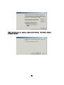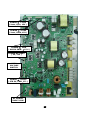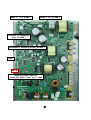
1
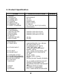
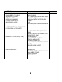
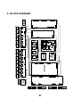
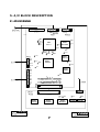
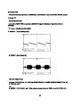
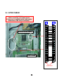
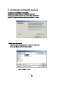
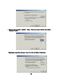
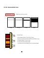
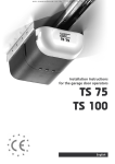
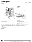
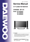
(FOR NEC MODULE)
CONTENTS
1. COMMENTS
2. SAFETY PRECAUTION
3. PRODUCT SPECIFICATION
4. BLOCK DIAGRAM
5. AV BLOCK DESCRIPTION
6. LVDS SPECIFICATIONS
7. SERVICE MODE (VIDEO PCB INITIAL DATA)
8. SOFTWARE UPGRADE METHOD
9. POWER ADJUSTMENTS
10.ASSEMBLY LIST
11.PDP MODULE CHECK POINT
11-1. Flow Chart
11-2. Serial Number
11-3. Panel Crack
11-4. Flexible Cable
11-5. Connectors
11-6. Tester Checking
11-7. Strip Defect
11-8. Vertical Line
11-9. Horizontal Line
12. EXPLODED VIEW
1
1. COMMENTS
This paper is the additional service manual for the
DP-42SM/WM/GM using the NEC panel.
Other service contents with the exception of this
manual are same as the existing service manual
(DP-42SM/WM/GM). The existing service manual
was made for ORION panel.
2
2. Saf ety Precautions
(1) When moving or laying down a PDP Set, at least two people must be working.
Avoid any impact towards the PDP Set.
(2) Do not leave the broken PDP Set on for a long time. To prevent any further
damages, after check the broken Set's condition, make sure to turn the power
(AC) off.
(3) When opening the BACK COVER, turn off the power (AC) to prevent electric
shock. When a PDP is on, high voltage and high current exist inside the Set.
(4) When loosening screws, check the connecting position and type of the
screw. Sort out the screws and store them separately. Because screws holding
PCB are working as electric circuit GROUNDING, make sure to check if any
screw is missing when assembling.
(5) If you open the BACK COVER, you will see a Panel Gas Exhaust Tube.If this
part is damaged, entire PDP PANEL must be replaced. Therefore, when working,
be careful not to damage this part.
(6) A PDP Set contains different kind of connector cables. When connecting or
disconnecting connector cables, check the direction and position of the cable
beforehand.
(7) When disconnecting connectors, unplug the connectors slowly with care.
Especially when connecting/disconnecting FFC (film) cables or FPC cables, do
not unplug the connectors too much instantaneously or strongly, and always
handle the cables with care.
(8) Connectors are designed so that if the number of pins or the direction does
not match, connectors will not fit. When having problem in plugging the
connectors, make sure to check their kind, position, and direction.
3
3. Product Specification
ITEM
1. GENERAL
1-1. MODEL NO
1-2. CHASSIS NO
1-3. SCREEN SIZE
1-4. COUNTRY
1-5. RESOLUTION
1-6. REMOCON TYPE
1-7. SAFETY STANDARD
2. MECHANICAL
2-1. APPEARANCE
1) WITHOUT STAND
2) WITH STAND
3) CARTON BOX
2-2. WEIGHT
1) WITHOUT STAND
2) WITH STAND
3. ELECTRICAL
3-1. VIDEO INPUT
3-2. DTV/DVD INPUT
3-3. PC INPUT
3-4. SOUND INPUT
3-4. SPEAKER OUTPUT
3-5. POWER REQUIREMENT
3-6. POWER CONSUMPTION
3-8. RS-232 CONTROL
3-9. FUNCTION
1) SCALING
2) ZOOM
3) OSD
4) OTHERS
SPECIFICATION
DSP-4280NVS
SP-115
42”(16:9)
WORLD WIDE
853(H) X 480(V)
R-V28A (E)
UL, C-UL, CE, CB, FCC(CLASS B),
CE(CLASS B)
WxHxD=1,039 x 628 x 80 mm
WxHxD=1,039 x 725 x 320 mm
WxHxD=1,256 x 800 x 327 mm
29.9 Kg
36.8 Kg
COMPOSITE(NTSC, PAL, SECAM,
PAL-M/N, NTSC4.43) &
S-VHS(50/60Hz Y/C) 2SETS
1080 i, 720P, 480P , 480i
(Y, Pb/Cb, Pr/Cr COMPONENT
SIGNAL) 2SETS
VGA ~ UXGA (15 PIN D-SUB) 1SET
VIDEO 2SETS, DTV/DVD 2SETS,
PC 1SET
8W(R) + 8W(L)
AC 100V~240V, 50/60Hz
320W
RS-232(FOR SOFTWARE UPGRADE)
PC: H/V SIZE & POSITION ADJUST
VIDEO/DTV/DVD:NOMAL,16:9,
PANORAMA,ENLARGE LB,ENLARGE
LBS
20 SCALE ZOOM & PANING
SUPPORT 11 LANGUAGES
STILL, SLEEP MODE,SOUND MODE
4
REMARK
4. OPTICAL
ITEM
4-2. ASPECT RATIO
4-3. NUMBER OF PIXELS
4-4. DISPLAY COLOR
4-5. PIXEL PITCH
4-6. PEAK LUMINANCE
4-7. CONTRAST RATIO
4-8. VIEWING ANGLE
SPECIFICATION
16:9
853(H)X480(V)
16.77 MILLION COLOR (8BIT RGB)
1.08(H)X1.08(V)
300cd/m³ (WITH FILTER GLASS)
1500:1
160
DEGREE(VERTICAL/HORIZONTAL)
5. USERCONTROL & ACCESSORY
5-1 CONTROL BUTTON(SET)
5-2. REMOTE CONTROL(R-V28)
5-3. ACCESSORIES
AC POWER BUTTON(PUSH-PULL
S/W)
MENU, SELECT, UP, DOWN, LEFT,
RIGHT(SOFT S/W)
POWER,INPUT
SELECT,DISPLAY,ZOOM-,
ZOOM+, MENU, UP,
DOWN,VOLUME UP,
VOLUME DOWN,FREEZE,SCREEN
MODE,
SOUND MODE,SLEEP
REMOCON,
BATTERY,INSTRUCTION MANUAL
A/V CABLE,STAND,
WALL HANGER,
SPEAKER R/L
5
REMARK
4. BLOCK DIAGRAM
6
5. A/V BLOCK DESCRIPTION
5-1. A/V BLOCK DIAGRAM
7
5-2.VIDEO PCB
- PROCESS Various Signal (PC, COMPONENT, COMPOSITE ) to produce 24BIT DIGITAL output
1) IC and TP
(1) IC400(UPD64083)
-Using 3D COMBFILTER to separate COMPOSITE signal to Brightness Signal(Y) and Color
Signal(C)
*TP ( Input : COLOR BAR PATTERN )
A. YCOMP : Brightness Signal(Y)
B. CCOMP : Color Signal (C)
(2) IC401 (SAA7118E)
-Receive NTSC, SECAM, PAL VIDEO by COMPOSITE(V) , S-VHS(Y.C) COMPONENT (Y Cb Cr)
and process signal
*TP
A. DECOE : CHIP ENABLE part. When signal process is done by IC401, output 3.3V DC LEVEL
8
(3) IC406 (DPTV-MVS)
-A Scan Rate Converter which converts Interlace signal into Progressive signal
*TP
A. VVS : VERTICAL SYNC (output by DPTV-MVS)
B. VHS : HORIZONTAL SYNC (output by DPTV-MVS)
C. VCLK : CLOCK (output by DPTV-MVS)
9
(4) IC500 (CXA3516R)
-3-channel 8-bit 165MSPS A/D converter which process PC , DTV signal
* TP
A. GCOAST : COAST CONTOL Signal for PLL (input by CXA3516)
B .GHS : HORIZONTAL SYNC for GRAPHIC (output by CXA3516)
C. GCLK : CLOCK for CLOCK (output by CXA3516)
10
D. GFBK : SYNC for PLL
(5) IC600 (PW171) - Image processor IC
*TP
A. DEN : DATA ENABLE (output by PW171)
B. DHS : HORIZONTAL SYNC (output by PW171)
11
C.DVS : VERTICAL SYNC for DISPLAY (output by PW171)
D. DCLKB : CLOCK for DISPLAY (output by PW171)
5-3. JACK PCB
- Separate and process various VIDEO and AUDIO signal
(1) IC706(VIDEO /SYNC SELECTOR)
- This chooses Y Cb/Pb Cr/Pr or RGB signal to output Y Cb/Pb Cr/Pr, to separate SYNC, and to
perform SYNC COUNTER.
(2) IC704(7_INPUT 3_OUTPUT AUDIO/VIDEO SWITCH)
- The IC perform AUDIO or VIDEO SWITCHING
(3) IC700(MULTI STANDARD SOUND PROCDSSOR)
-AUDIO SINGNAL VOLUME control, EQUALIZER control
12
*TP
R_OUT(L_OUT) : AUDIO SIGNAL that goes into MSP3420 before AUDIO PROCESSING
(4) IC701 .IC700 (TDA 7480)
*TP
A. RIGHT(LEFT) :AMP input signal before 30dB amplification
4-1-4.KEY PCB
-Input PCB using KEY
4-1-5.LED PCB
- PCB for REMOCON CONTROL
13
6. LVDS CABLE
CAUTION!
After servicing, you must check
if ring core is coupled with LVDS cable.
Otherwise, PDP may not display.
DIGITAL BOARD (PANEL)
VIDEO BOARD
14
7. SERVICE MODE (VIDEO PCB INITIAL DATA)
(1) Input Selection : VIDEO
(2) USER CONTROL INITIAL VALUE
BRIGHTNESS : 35, CONTRAST : 47, COLOR : 32, TINT : 0 (CENTER)
SHARPNESS : 4
(3) SERVICE MODE INITIAL VALUE
1) PW171
SUB-BRIGHTNESS : 28, SUB-CONTRAST : 40
R-BIAS : 64, G-BIAS : 64, B-BIAS : 64
R-GAIN : 64, G-GAIN : 64, B-GAIN : 64
2) SAA7118
SUB BRT : 128, SUB CONT : 50, SUB CLR : 55, SUB TNT : 0
SUB SRP : 10
3) DPTV
SUB BRT : 61, SUB CONT : 16,
4) CXA3516
SUB CONT : 58, Cb OFFSET : 39, Cr OFFSET : 37, HYS : 3,
THRSLD : 14
5) MSP34X0
PRESCALE : 22
6) PANEL
MOVING : Video60STD
STILL : Video60RFC
15
8. SOFTWARE UPGRADE Method
1.Connect the JACK PCB to the Video PCB.
2.Connect 9 PIN serial cable to the computer’s serial port.
3.Connect serial cable’s opposite end to Jack PCB’s RS-232C port.
4.Run PC’s Flashupgrader.exe and then push “Next(N) >” button.
1.Select current Upgrade file
-Copy files sent by research center to a folder you wish to copy.
-Browse and Select pwSDK.inf from the folder.
-Push “Next(N) >” button.
16
1. Select as above and push “Next(N) >” button. Select Comm port and Boud rate and push
“Next(N) >” button
1.Upgrade process will be displayed. Power the AC on will initiate the download.
17
1.When all files Upgrade are complete, a window (below) will open. Push “Finish” button to
complete the process.
18
9. POWER ADJUSTMENTS
1. Vsus (SUSTAIN Voltage) : Discharge Sustain Voltage
. METER used : DIGITAL MULTIMETER (DC Voltage Measure Mode)
. Adjusting TP : TP204 (refer to PAGE 11)
. Adjusting VOLUME : RV203 (refer to PAGE 11)
. Standard Voltage : 170V (This value could be different from the optimum
adjusting voltage)
. Optimum adjusting Voltage : Stated in the LABEL
(See voltage adjustment label in the top of Panel Back Plate - PAGE 11)
2. Vadd (ADDRESS voltage) : DATA Input Voltage
. METER used : DIGITAL MULTIMETER (DC Voltage Measure Mode)
. Adjusting TP : TP206 (refer to PAGE 11)
. Adjusting VOLUME : RV204 (refer to PAGE 11)
. Standard Voltage : 60V (This value could be different from the optimum
adjusting voltage)
. Optimum adjusting Voltage : Stated in the LABEL
(See voltage adjustment label in the top of Panel Back Plate - PAGE 11)
*. As NEC Panel doesn't apply Vyer, it is unnecessary to adjust.
19
POWER ⇒ Y-SUS
( Vsus, Vyer, 15V )
POWER ⇒ X-SUS
( Vsus, Vadd, 15V )
POWER ⇒ JACK
( AUDIO PWR : ± 15 V )
POWER ⇒ VIDEO
( 5V, 12V )
HIGH
VOLTAGE
SWITCH
POWER ⇔ VIDEO
( STB 5V, PWR_CTL )
AC POWER
INPUT LINE
20
Vsus ‘s
TP ( TP204 )
Vadd ‘s TP ( TP206 )
VOLUME for adjusting
Vsus ( RV203 )
VOLUME for adjusting Vadd ( RV204 )
GND
Ï ON
HIGH VOLTAGE SWITCH
*HIGH VOLTAGE : Vsus, Vyer, Vadd
21
10. ASSEMBLY LIST
No.
PCB ASS'Y NAME
ASS'Y CORD
ASS'Y DESCRIPTION
1
VIDEO PCB AS
PTVDMSG009
PCB VIDEO MANUAL AS
2
JACK PCB AS
PTJAMSG009
PCB JACK MANUAL AS
3
5V SUB PCB AS
PTSBMSG009
PCB SUB MANUAL AS
4
MODULE PDP
4850M06110
NP42B2MF02
5
X-SUS PCB AS
485AS00290
X-SUS PCB AS (NP42B2MF02 NEC)
6
Y-SUS PCB AS
485AS00390
Y-SUS PCB AS (NP42B2MF02 NEC)
7
DIGITAL PCB AS
485AS00490
DIGITAL PCB AS (NP42B2MF02 NEC)
8
CONN CENTER AS
485AS00790
CONN CENTER AS (NP42B2MF02 NEC)
9
CONN LEFT AS
485AS00590
CONN LEFT AS (NP42B2MF02 NEC)
10
CONN RIGHT AS
485AS00690
CONN RIGHT AS (NP42B2MF02 NEC)
11
PANEL GLASS
485AS00190
PANEL GLASS (NP42B2MF02 NEC)
12
GLASS FILTER
4952400200
PDF-6PH02
13
MODULE POWER
4850M05910
PDD-421
14
CONNECTOR
4850711N04
YMH025-11R+YMH025-11R+ULW=230
15
CONNECTOR
4850707N11
YMH025-07R+YMH025-07R+ULW=220
16
CONNECTOR
4850709N06
YMH025-09R+YH396-09V+ULW=400
17
CONNECTOR
4850710N09
YMH025-10R+YH396-10V+ULW=310
18
CONNECTOR
4850704N29
A2501H02-4P+440133-4+ULW=410
19
CONNECTOR
4850710N08
YMH025-10R+YMT025R+ULW=500
20
CONNECTOR
4850705N27
YMH025-05R+YMT025R+ULW=500
21
CONNECTOR
4950706025
12505HS-06+12505TS+ULW=750
22
CONNECTOR
4850705N28
12505HS-05+12505TS+ULW=900
23
CONNECTOR
4850704N28
YMH025-04R+YMT025R+ULW=400
24
CABLE FFC
485900038L
0.5-R-50P-320MM 6X4-6X4
25
CABLE FFC
485900018L
0.5-K-50P-400MM 6X4-6X4
26
CABLE FFC
485900028L
0.5-K-50P-360MM 6X4-6X4
27
FILTER EMI
5PZCAT3035
ZCAT3035-1330
28
BRKT MAIN
4853954100
SECC T1.0
29
SUPPORT CIRCUIT C
4957300400
PCBEHE2-25M-01
22
11. PDP MODULE CHECK POINT
11-1. Flow Chart
Check process
Type, Serial Number
Panel Crack
Take pictures (Module and shipment box)
Flexible Cable
Take pictures
Connectors
Take pictures
Tester Checking
If you can confirm visual malfunction,
take pictures
Phenomenon
Input it in your line again
Each
Strip Defect
Vertical Line Horizontal Line No Display Writing Issues
Page 38-39 Page 41-44
Page 45
Judgment (Make C-PDP Failure Description sheet)
23
11-2. Serial Number
Module Number and Panel ID
SERIAL NO.
Serial No.
302200129
Panel ID
Vd=60V
222301242941
Vs=168.4V
Type
CODE CA-01
24
11-3. Panel Crack
Panel Crack
Check the surface of glass whether crack or not
This issue may be caused by transportation or treatment after shipment.
We would like you to take some pictures, the broken module, the outside box,
and inform the shipment data
If you do not the pictures, we can dispose the broken modules on our responsibility.
25
11-4. Flexible cable
Flexible Cable
Check the Flexible Cables whether scratched, broken, or not.
Cutting cable or broken
In this case, it caused by handling them at customer line.
We would like you to be careful to handle the modules.
26
11-5. Connectors
Connectors Condition
Check the Cable or Connectors whether connected and locked, or not
NEC MODULE ONLY (with the exception of video, power and jack board)
DIGITAL BOARD
5 connectors
SCAN BOARD
11 connectors
COMMON BOARD
7 connectors
DATA RELAY BOARD 2 connectors
DATA RELAY BOARD 2 connectors
We would like you to be careful to handle the modules at assembling
27
Each Connectors Condition
Data HIC
-DATA RELAY BOARD
DIGITAL BOARD
DIGITAL BOARD
-DATA RELAY BOARD
LOCKED
UNLOCKED
28
-DATA RELAY BOARD
SCAN BOARD
-SACN DRIVING BOARD
Each Connectors Condition
COMMON BOARD
DIGITAL BOARD
- FLEXIBLE CALBLE
- FLEXIBLE CALBLE
LOCKED
CONNECTED
UNLOCKED
UNCONNECTED
29
11-6. Tester Checking
Fuse Checking
Glass fuse
Glass fuse
(F1 and F2)
(F1 and F2)
on Common Board
on Scan Board
OK :
Shortage
NG :
Opened
OK :
Shortage
NG :
Opened
Fuse resistance
Fuse resistance
(R101)
(R12 R29)
on Common Board
on Scan Board
R12 OK : 2.2
ohms
R29 OK : 4.7
ohms
OK : 2.2
ohms
NG :
Opened
30
Alarm Line
Checking
Glass Alarm
Glass Alarm
At #50 pin on CN8
between pins on CN3
On Data Relay Board
On Scan Board
(Right-Down)
OK :
Shortage
NG :
Opened
OK :
Shortage
NG :
Opened
31
Data HIC line
Checking
F2 fuse and GND on scan board
Between F2 fuse and GND
OK :
Opened
NG :Short
age
F2 fuse and GND on scan board
Between F2 fuse and GND
Check between F2 fuse and GND at scan or common board.
If it is shortage,
Remove the heatsink over the data HIC,
And Check the surface of data HIC, the take a picture
OK : Opened
NG :Shortage
32
Parts Location
COMMON Board
COMMON Board
PH2101
PH2101
PH2102
33
Power HIC Checking
PH2101 on Common board
Check the following
cases.
PH2101 on common board
A
G
B
H
C
PH2101
D
PH2101
E
F
Between A and G
Between B and H
Between C and D
Between E and F
34
OK : More than
K ohm
NG : Shortage
Power HIC Checking
PH2101 on Scan board
Check the following cases.
PH2101 on scan board
F
E
D
PH2101
C
PH2101
B
H
G
35
A
Between A and G
Between B and H
Between C and D
Between E and F
OK : More than
K ohm
NG : Shortage
Power HIC Checking
PH2102 on Scan
board
Check the following
cases.
PH2101 on common board
A
B
C
PH2102
D
E
F
G
H
I
J
PH2102
K
Between A and B
Between B and C
Between D and E
Between F and G
Between H and I
Between J and K
36
OK : More than
K ohm
NG : Shortage
SCAN IC Driver Checking
Scan IC
NEGA
Scan
IC
POSI
NEGA
POSI
OK : More than K ohm
NG : Shortage
Check the following cases.
Between NEGA and POSI
37
11-7. Strip Defect
Strip Defect
Compare with specification
1 Strip
2 Strip
38
2 Strip
Strip Defect
3 Strip
3 Strip
39
3 Strip
11-8. Vertical Line
Vertical Line
Single line
Open Mode
ALL Red
Pattern
ALL Green
Pattern
ALL Blue
Pattern
ALL Black
Pattern
Black 1 Line
Red 1 Line
Red1 Line
No
Appearance
Red 1 Line Open
Mode
[Check Point]
a)
The broken data flexible cable.
If OK, Data IC Broken.
40
Vertical Line
Two line
Shortage Mode
ALL Red
Pattern
ALL Green
Pattern
ALL Blue
Pattern
ALL Black
Pattern
Blue 1 Line
No
Appearance
Red1 Line
No
Appearance
Shortage between Red and
Blue
[Check Point]
a)
This phenomenon is caused by panel issues.
41
Vertical Line
Block
1/2 data IC Block (width
30mm)
[Check Point]
a) The broken surface IC on data IC.
b) The broken data flexible cable.
42
Vertical Line
Block
1 data IC Block
[Check Point]
a) Lacking connector between Data Relay board and Data IC.
b) The broken data flexible cable.
43
Vertical Line
Block
Many data IC Block
[Check Point]
a) Lacking connector between Data Relay board and Scan or Common board
b) The broken data flexible cable
c) Shortage between leads in connector.
Foreign Material etc.
44
11-9. Horizontal Line
Horizontal Line
Single
Single line, two lines or block
Two Line
NEGA
Block
Block
[Check Point]
a)The broken surface IC on scan IC driver.
Check the resistance between NEGA and POSI on scan
POSI
IC board. (Normal : K ohm Level)
b) The broken data flexible cable.
c) Lacking connector between scan IC and scan board.
NEGA
45