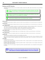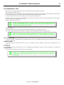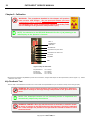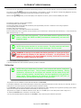
1
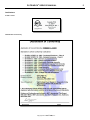
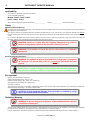
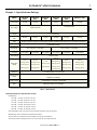
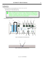
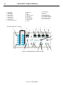
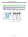
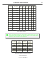
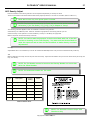
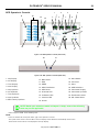
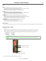
PATRIARCH High Frequency X-ray Generator Service Manual Models: P200, P300, P400, P500, P600, P700 PATRIARCH ® SERVICE MANUAL 2 Table of Contents Preface3 Chapter 4: Setup22 Warranty3 Overview22 Presentation3 Power On Test 23 Notation3 Blue Watch Dog LED23 Certifications5 Power On23 Applicability6 Pre-Set #s25 Safety6 mA Station Selection26 Environment6 X-Ray Tube Selection27 Radiation Warning6 mA Station Selection28 Chapter 1: Specifications7 Filament Standby Number28 Ratings7 HV Cable Length29 Maximum Technique Selections Buckys and AEC Selection 8 30 Configuration9 Maximum kVp30 Operator’s Console9 Rotor Speed30 Chapter 2: Installation11 Low Speed Boost Time31 Site Preparation11 Interlock Selection31 Unpacking11 Chapter 5: Calibration32 Inspection11 kVp Feedback Test32 Mechanical Installation12 Calibration33 Interconnection13 Manual Calibration 36 P1/P2 Cable13 AUTOCAL36 Interconnecting Cable13 AEC Density Adjust37 Hand Switch 13 Chapter 6: Compliance Testing 38 Chapter 3: Interface14 Overview38 Mains14 Configuration38 Single Phase, 220 VAC 14 Operator’s Console39 3 Phase, 220 VAC 14 APR Operator’s Console39 Buckys16 Exposure Factor Tests41 SYSTEM BUCKY CONNECTIONS 17 kVp/mA42 SIMPLIFIED BUCKY CONNECTIONS 17 Time43 Rotor18 Reporting44 External Handswitch/Footswitch18 Chapter 7: Error Codes45 Vet Footswitch for “One Touch” Operation 18 Overview45 Interlocks19 Error Codes46 AEC19 SCHEMATICS49 Auxillary Relay20 24 VAC Collimator Lamp Power 20 External Exposure Indication 21 High Speed Starter Interface 21 Copyright 2011 by GTR LABS, Inc. All rights reserved. Contents of this publication may not be reproduced in any form or by any means, electronic or mechanical, including photocopying and recording, or by any information storage or retrieval system without the written permission of: GTR LABS, Inc. 510 Elk Street Gassaway, WV 26624 Telephone: 304-364-2211 web: www.gtrllc.com email: [email protected] PATRIARCH ® SERVICE MANUAL 3 Preface Warranty GTR ® LABS, Inc. warrants that this product will be free from defects in materials and workmanship for a period of five (5) years from the date of installation at the first end user’s site; If any such product proves defective during this warranty period, GTR ®, at it’s option, either will repair the defective product without charge for parts or shop labor, or will provide a replacement in exchange for the defective product. This warranty shall apply to all equipment and systems sold by GTR ® with the exception of the following: X-Ray Tubes Image Intensifiers TV Camera Tubes The above items are subject to the manufacturer’s warranty in effect as of the date sold. These warranties vary and are pro-rated. The manufacturer will be the final authority for any warranty claim. In order to obtain service under this warranty, Customer must notify GTR ® of the defect before the expiration of the warranty period and make suitable arrangements for the performance of service. Customer shall be responsible for packaging and shipping the defective product to the service center designated by GTR® with shipping charges prepaid. GTR® shall pay for the return of the product to Customer if the shipment is to a location within the country in which the GTR ® designated service center is located. Customer shall be responsible for paying all shipping charges, duties, taxes, and any other charges for products returned to any other locations. This warranty shall not apply to any defect, failure, or damage caused by improper or inadequate maintenance and care. GTR ® shall not be obligated to furnish service under this warranty 1) to repair damage resulting from attempts by personnel other than GTR ® representatives to install, repair, or service this product; 2) to repair damage resulting from improper use or connection to incompatible equipment or power source; or 3) to service a product that has been modified or integrated with other products when the effect of such modification or integration increases the time or difficulty of servicing the product. Further, GTR ® LABS, Inc. warrants that the product is in compliance with U.S.A. DHHS regulations which may be in force and effect at the time of shipment of the product. The following is not covered by the warranty: General maintenance and simple adjustments mentioned in the manuals delivered with the material. THIS WARRANTY IS GIVEN BY GTR ® WITH RESPECT TO THIS PRODUCT IN LIEU OF ANY OTHER WARRANTIES, EXPRESS OR IMPLIED. GTR ® AND IT’S VENDORS DISCLAIM ANY IMPLIED WARRANTIES OF MERCHANTABILITY OR FITNESS FOR A PARTICULAR PURPOSE. GTR ®‘S RESPONSIBILITY TO REPAIR OR REPLACE DEFECTIVE PRODUCTS IS THE SOLE REMEDY PROVIDED TO THE CUSTOMER FOR BREACH OF THIS WARRANTY. GTR ® AND IT’S VENDORS WILL NOT BE LIABLE FOR ANY INDIRECT, SPECIAL, INCIDENTAL, OR CONSEQUENTIAL DAMAGES IRRESPECTIVE OF WHETHER GTR ® OR THE VENDOR HAS ADVANCE NOTICE OF THE POSSIBILITY OF SUCH DAMAGES. There are no warranties which extend beyond the description mentioned in this document. Presentation This manual contains information on the installation of the Patriarch generators. Notation NOTE: This is an example of a NOTE. NOTES are areas that need additional attention. CAUTION: This is an example of a CAUTION. CAUTIONS are procedures that the operator must heed in order to avoid damage to the equipment. WARNING: This is an example of a WARNING. WARNINGS are procedures that the operator must heed in order to avoid bodily harm or injury. Copyright 2013 GTR LABS, Inc. 4 PATRIARCH ® SERVICE MANUAL This page is blank. Copyright 2013 GTR LABS, Inc. PATRIARCH ® SERVICE MANUAL Certifications: UL 2601-1 Listed CE Declaration of Conformity Copyright 2013 GTR LABS, Inc. 5 PATRIARCH ® SERVICE MANUAL 6 Applicability This manual is applicable to the Patriarch Series, Single Tube RAD generators. Models: P200T, P300T, P400T, P500T, P600T, P700T This manual is shipped with generator Model # ________________, Serial #______________, with Software Version ___________. Safety Mechanical-Electrical Warning All of the electronic assemblies and parts of this equipment should be operated with care and routinely inspected in accordance with the manufacturer’s recommendations. Only properly trained and qualified personnel should be permitted access to any internal parts. Live electrical terminals are LETHAL. Be sure line disconnect switches are opened and other appropriate precautions are taken before removing covers or attaching accessories. Do not remove the flexible high tension cables from the x-ray tube housing or high tension generator, and/or the access covers from the generator until the main and auxiliary power supplies have been disconnected. WARNING: Failure to comply with the foregoing safeguards may result in serious or fatal bodily injuries to the operator or those in the area. WARNING: This product is not to be used in the presence of flammable anesthetics. Electrical Grounding Instructions WARNING: The equipment must be grounded to an earth ground by a separate #8 conductor. The neutral side of the line is not to be considered the earth ground. NOTE: This is “Type B” Equipment which employs both insulation protection and protective earthing to reduce the risk of electric shock to product users. Environment Storage and Transportation conditions: Ambient Temperature Range: -40C to +70C Relative Humidity Range: 10 to 100% (non condensing) Atmospheric Pressure Range: No requirements Operation Conditions: This equipment is designed to work within a temperature range of 20 0C to 30 0C, with a relative humidity (non-condensing) less than 60%. Atmospheric Pressure Range: -15 meters to 3000 meters. CAUTION: Provide adequate filtration if the generator is installed in a high dust or particulate matter environment. Radiation Warning WARNING: X-rays are dangerous to operator unless established safe exposure procedures are observed. The useful and scattered beams can produce serious or fatal bodily injuries to any persons in the immediate or surrounding area. Adequate precautions should be taken to avoid exposure to the central beam or to scattered radiation. Persons authorized to operate the equipment should be familiar with the established safe exposure factors and procedures. Copyright 2013 GTR LABS, Inc. PATRIARCH ® SERVICE MANUAL 7 Chapter 1: Specifications Ratings Model Patriarch 200T Patriarch 300T Patriarch 400T Patriarch 500T Patriarch 600T Patriarch 700T Power Rating 12.5 kW 25.0 kW 37.5 kW 40.0 kW 50.0 kW 60.0 kW 1 Phase, 240 VAC Line Voltage 3 Phase 240 VAC 3 Phase 240 VAC Line Voltage Range +/- 10% (50/60 Hz) Circuit Breaker Size 50 Amp 50 Amp 75 Amp 100 Amp 100 Amp 100 Amp Wire Type/ Size Stranded Copper #2 Wire (6.54mm diam) for runs less than 50 feet, #0 Wire (8.25mm diam) for runs more than 50 feet Power Line Requirements 0.30 Ohms or less kVp Range 40 to 125 kVp in 1 kVp steps mA Range 25 to 200mA 25 to 300mA 40 to 150 kVp in 1 kVp steps 25 to 400mA Timer Range Max Power Output 25 to 500mA 25 to 600mA 25 to 600mA 50.0 kW 60.0 kW 300mA @ 150 kVp 400mA @ 125 kVp 400mA @ 125 kVp 500mA @ 120 kVp 500mA @ 100 kVp 600mA @ 100 kVp .002ms to 6 sec. 12.5 kW 25.0 kW 100mA @ 125 kVp 200mA @ 125 kVp 150mA @ 80 kVp 250mA @ 100 kVp 200mA @ 60 kVp 300mA @ 80 kVp 40.0 kW 37.5 kW 250mA @ 150 kVp 300mA @ 125 kVp 300mA @ 140 kVp 400mA @ 90 kVp 400mA @ 100 kVp 500mA @ 80 kVp Technique Selection 4 Point Display (kVp, mA, Time, mAs) Auxiliary Power Supply Collimator Lamp Supply Bucky Control Included Bucky 1 and Bucky 2 Selectable AEC Optional to Control 3 Ion Chambers Magnetic Lock Supply Table 1-1: Specifications Technique Factors for maximum line current: Radiographic: 12.5 kW 125 kVp @ 100 mA > 20 ms 25.0 kW 125 kVp @ 200 mA > 20 ms 37.5 kW 125 kVp @ 300 mA > 20 ms 40.0 kW 100 kVp @ 400 mA > 20 ms 50.0 kW 100 kVp @ 500 mA > 20 ms 60.0 kW 100 kVp @ 600 mA > 20 ms The radiographic duty cycle can be one maximum exsposure every 30 seconds. Methodology used to measure actual technique factors: The kVp and mA is measured as the aveage of the top of the waveform. The exposure time is measured from 75% of rise and fall of the kVp waveform. Copyright 2013 GTR LABS, Inc. 8 PATRIARCH ® SERVICE MANUAL NOTE: Maximum allowable techniques for IPM Protection (see chart below). Table 1-1A Maximum Technique Selections Copyright 2013 GTR LABS, Inc. PATRIARCH ® SERVICE MANUAL 9 Configuration Operator’s Console There are two Operator’s Consoles available with the Patriarch family of generators: APR Operator’s Console (Part Number 6072.00) VET APR Operator’s Console (Part Number 6103) NOTE: Throughout the Technical Manual references are made to various aspects of the Operator’s Console. These include the reconfiguration of displays during Setup (Chapter 4), Calibration (Chapter 5) and Compliance (Chapter6). Familiarize yourself with the specific Operator’s Console supplied with your system and take note of it’s characteristics. APR Operator’s Console 21 1 22 23 5 24 2 6 3 7 4 8 9 10 18 26 25 17 16 15 14 13 Figure 1-1A APR Operator’s Console (Front View) 20 19 Figure 1-1B APR Operator’s Console (Rear View) Copyright 2013 GTR LABS, Inc. 12 11 PATRIARCH ® SERVICE MANUAL 10 1. 2. 3. 4. 5. 6. 7. 8. 9. kVp Display mA Display Time Display mAs Display kVp Up/Down mA Up/Down Time Up/Down mAs Up/Down AEC Density Up/Down 10. 11. 12. 13. 14. 15. 16. 17. 18. 19. 20. 21. 22. 23. 24. 25. 26. BKY Select EXP PREP AEC Field Select AEC Reset Overload LED Collimator LED Interlock LED On/Off VET APR Operator’s Console 21 1 22 23 2 5 24 Hand Switch Connector Store APR Selections Centimeter Display Centimeter Up/Down Film/Screen Select A/P-Lateral-Other 6 3 7 4 8 9 10 18 25 26 17 16 15 14 13 Figure 1-3A VET APR Operator’s Console (Front View) Copyright 2013 GTR LABS, Inc. 12 11 PATRIARCH ® SERVICE MANUAL 11 Chapter 2: Installation Site Preparation The following factors should be considered when selecting a site for installation of the Cabint: Environment: This equipment is designed to work within a temperature range of 20°C to 30°C, with a relative humidity (non-condensing) of less than 40%. Proximity to Mains Disconnect: L1/L2/L3 connections should be as short as possible in order to minimize line drop during an exposure. NOTE: If less than 15’ use #6 stranded wire from Mains Disconnect to F1/F2/ F3. If greater than 15’ use #4 stranded wire. Consult Local Electrical Code for the proper wire size between Mains Disconnect and Source. WARNING: For proper operation of the generator you may not increase the length of the Interface Cable or the P1/P2 Cable. Unpacking The generator is shipped in one carton. Carefully inspect the exterior of the carton for external damage. Report any damage immediately to the carrier. Damage due to mishandling during shipping or transportation is specifically not covered by the manufacturer’s warranty. NOTE: Damage due to mishandling during shipping or transportation is specifically not covered by the manufacturer’s warranty. Open Carton - Remove the Cabinet Cover. Unbolt and Remove the HV Tank. HV Tank NOTE: Due to pressure changes in shipping and transportation, residual amounts of oil may leak from the HVT and be evident on the carton or packing materials. Release the seal on the HV Tank (with the HV Tank in it’s normal, upright position) by turning the wing nut on top of the filler plug counterclockwise several times until it is loose. Inspection WARNING: It is critical that you conduct a complete visual inspection of the components of the generator after unpacking. Every precaution is taken during the final test and packing procedures to ensure that all screws and fasteners are secured tightly and that all circuit boards are seated properly. However, it is the responsibility of the installer to inspect carefully prior to the first application of power. Failure to follow this step could result in damage to the generator as well as injury to personnel. Copyright 2013 GTR LABS, Inc. PATRIARCH ® SERVICE MANUAL 12 HV Tank The High Voltage cable wells are covered by red plastic plugs. Remove the plugs and ensure that the wells are clean and free of any contaminant. Inspect the sides of the tank. They should be smooth and without indentations. Inspect the pins on the Interface Connector. Remove any residue that may have accumulated during shipping. Ensure that all the pins are straight. Remove the cover protecting P1/P2 and inspect the brass studs. Note the presence of the proper mounting hardware. Cabinet Inspect the cover of the Cabinet. It should be smooth without any indentations other than the air vents. Operator’s Console Unwrap and inspect the Operator’s Console. The metal case should be solid and without cracks or scratches. The graphic overlay should be without blemish and you should be able to see each of the 7 segment LED displays through the filters on the display windows. The rear panel should be intact with the connector for the Interconnecting Cable and the Hand Switch. Mechanical Installation Cabinet The cabinet can be mounted Free Standing, attached to the Wall, or mounted on the wall above floor level. Cable access is through the knockouts on left or right side of the cabinet. HV Tank The HV Tank weighs approximately 55 lbs and must be mounted in an upright position on the bottom of the cabinet. If the local building code requires that the HVT be secured mechanically to a mounting surface, you may drill holes in the bottom shelf of the Wall Mount Bracket. Operator’s Console The Operator’s Console is designed to mount on a shelf or desk top, or optional pedestal. The 25’ (7.5 meter) Interconnecting Cable connects between the rear of the Operator’s Console and J45 connector on the BBU PCB. Copyright 2013 GTR LABS, Inc. PATRIARCH ® SERVICE MANUAL 13 Interconnection Interconnection of the generator consists of three cables supplied with the generator. P1/P2 Cable This consists of 2 #8 Red Wires and a #8 Green/Yellow Ground Wire. #6 round terminals are attached to the open end of the cable for connection to the P1/P2 and Ground studs on the HV Tank. The ground wire attaches to the Ground stud. Connect the other two wires to P1 and P2. The order is not critical. CAUTION: P1/P2 connections are brass studs. It is possible to strip the threads on these studs or break them if you over tighten the locknuts. Do not use excessive force when tightening these connections. Interface Cable The Interface Cable connects the HV Tank to the Chassis. It consists of a 30” (80 cm) cable with a single connector on the HV Tank end and two (2) connectors on the Chassis end. (Refer to Figure 2-4) Connect the single connector to the HV Tank. At the Chassis connect the 4 conductor green Phoenix Connector to the TEC PCB. Connect the 9 pin D-Sub connector to the Feedback connector on the BBU PCB. Figure 2-4 Interface Cable Console Interconnecting Cable Route the 25’ (7.5 meter) Interconnecting Cable from the J45 Connector on the BBU PCB through conduit or trough to the Control Booth to the Operator’s Console. Hand Switch If your generator includes an optional Hand Switch, connect it to the rear of the Operator’s Console (refer to Fig. 1-1B {25}). This is a two position Hand Switch. The first position is PREP and the second position is EXP. These switches are in parallel with the PREP and EXP push buttons on the Operator’s Console. Figure 2-5 Hand Switch Copyright 2013 GTR LABS, Inc. PATRIARCH ® SERVICE MANUAL 14 Chapter 3: Interface Mains Input Line Voltage: For proper safe operation, you must match the input line voltage to the proper terminals on the Power Module Transformer. WARNING: Make sure the wires you move are the correct ones for the input taps on the Power Module Transformer. Failure to heed this caution will cause catastrophic failure of the Buss, Bridge Rectifier, Electrolytic Storage Capacitors and IPMs. Single Phase, 220 VAC Connect 220 VAC -/+10% 50/60Hz, 1 Phase to F1/F2 on the Single Phase 220VAC Power Module from Mains Disconnect. Refer to Figure 3-1A. NOTE: If less than 15’ use #6 (4.11mm diam) stranded wire from Mains Disconnect to F1/F2. If greater than 15’ use #4 (5.19mm diam) stranded wire. From Service Entry to Disconnect use Stranded Copper #2 Wire (6.54mm diam) for runs less than 50 feet, #0 Wire (8.25mm diam) for runs more than 50 feet (See Chapter 1 Specifications). WARNING: The equipment must be grounded to an earth ground by a separate #8 conductor. The neutral side of the line is not to be considered the earth ground. Measure the incoming line voltage at the input fuses. Your generator will have either F1/F2 setup shown below: F1/F2 F1/F2 Figure 3-1A F1/F2 Location Copyright 2013 GTR LABS, Inc. PATRIARCH ® SERVICE MANUAL 15 3 Phase, 220 VAC Connect 220 VAC -/+10% 50/60Hz, 3 Phase to F1/F2/F3 on the Three Pase 220VAC Power Module from Mains Disconnect. NOTE: If less than 15’ use #6 (4.11mm diam) stranded wire from Mains Disconnect to F1/F2/F3. If greater than 15’ use #4 (5.19mm diam) stranded wire. From Service Entry to Disconnect use Stranded Copper #2 Wire (6.54mm diam) for runs less than 50 feet, #0 Wire (8.25mm diam) for runs more than 50 feet (See Chapter 1 Specifications). WARNING: The equipment must be grounded to an earth ground by a separate #8 conductor. The neutral side of the line is not to be considered the earth ground. Measure the incoming line voltage at the input fuses. Your generator will have either F1/F2/F3 setup shown below: F1/F2/F3 F1/F2/F3 Ground Figure 3-1C F1/F2/F3 Location Copyright 2013 GTR LABS, Inc. PATRIARCH ® SERVICE MANUAL 16 Buckys Connect Bucky (or Buckys) to J9 Termnial Block on the SPB pcb. (Refer to Figure 3-2.) Input to the GCU is through the access hole on the Bottom Panel. Refer to Figure 1-6 in Chapter 1. WARNING: The Bucky Motion Inputs must be a “contact to ground” (NO VOLTAGE!). Any voltage on this input will result in damage to the equipment. J9 GND 1 Bucky 1 COM 2 Bucky 1 N.O. 3 Bucky 1 Motion 4 Bucky 2 COM 5 Bucky 2 N.O. 6 Bucky 2 Motion 7 Jumper VAC “A” 8 SPB pcb 9 10 11 12 VAC “B” BUCKY CONNECTIONS Figure 3-2 Bucky Connections VAC “A” to VAC “B” equals 220VAC VAC “A” or VAC “B” to GROUND equals 120VAC For Bucky’s supplied with 120VAC operation, use either VAC “A” or VAC “B” to GROUND. For Bucky’s supplied with 220VAC operation, use VAC “A” and VAC “B”. Follow the wiring directions on the label on the Bucky cable. The directions follow the diagram below. Bucky 1 is assumed to be the Table and Bucky 2 is assumed to be the Wall Stand in a 2 Bucky system. B uc ky C onn. B uc ky 1 B uc ky 2 B1 GND J 9-1 GND J 9-1 B2 B uc ky 1 Mot J 9-4 B uc ky 2 Mot J 9-7 B3 B uc ky 1 N/O J 9-3 B uc ky 2 N/O J 9-6 B4 220 VAC " B " 220 VAC " B " B6 E arth E art h B8 B uc ky 1 C OM J 9-2 B uc ky 2 C OM J 9-5 J umper J umper 220 VAC " A" to J 9-2 220 VAC " A" to J 9-5 Copyright 2013 GTR LABS, Inc. PATRIARCH ® SERVICE MANUAL SIMPLIFIED BUCKY CONNECTIONS 120 VAC BUCKY MOTOR CONNECTION (BUCKY 1) 240 VAC BUCKY MOTOR CONNECTION (BUCKY 1) WARNING: The Bucky Motion Inputs must be a “contact to ground” (NO VOLTAGE!). Any voltage on this input will result in damage to the equipment. BUCKY MOTION CONNECTION (BUCKY 1) Copyright 2013 GTR LABS, Inc. 17 PATRIARCH ® SERVICE MANUAL 18 Rotor Connect the Rotor to J9 Terminal Block on the SPB pcb. (Refer to Figure 3-5). Input to the Cabinet is through the access hole on the Left or Right Sidel. Refer to Figure 1-6 in Chapter 1. WARNING: The Common terminal for the Rotor(Rotor COM) is connected to one side of the AC Line at all times. DO NOT CONNECT AN X-RAY TUBE WITH A GROUNDED ROTOR TO THIS SYSTEM ! Failure to heed this WARNING will result in catastrophic failure of the x-ray tube in a very short time. J9 GND 1 2 3 4 5 6 7 GND Tube Thermal Interlock Rotor COM 8 SPB pcb External Handswitch/Footswitch Connect an External Handswitch/Footswitch to the J4 Terminal Block on the BBU. Refer to Figure 3-6. 9 10 Rotor Direct 11 Rotor Phase 12 All connections must be a “dry contact” (No Voltage!) to ground. J4 GND 1 PREP 2 EXP 3 BBU pcb Vet Footswitch for “One Touch” Operation Connect an External Single Position Footswitch to the J4 Terminal Block on the BBU. All connections must be a “ dry contact” (No Voltage) to ground. Figure 3-6 Handswitch/Footswitch Connections In Setup Mode at Setup Location [=28] enter a 1. This puts the generator in the “One Touch” mode. The first press of the footswitch initiates a PREP cycle which will last for 20 seconds. During this PREP cycle, the next press on the footswitch makes the exposure. NOTE: If using a two position footswitch - use the first position (Prep) and connect as indicated. Do not connect the second position. Copyright 2013 GTR LABS, Inc. PATRIARCH ® SERVICE MANUAL 19 Interlocks Connect Door and Collimator Interlocks to the J4 Terminal Block on the BBU pcb. Refer to Figure 3-7. All connections must be a “dry contact” (No Voltage!) to ground. J4 GND 1 COLLIMATOR 5 DOOR 6 BBU pcb Figure 3-7 Interlock Connections NOTE: Interlocks are disabled from the factory. If you use them you must enable them in Chapter 4, Setup. AEC Connect Ion Chambers to input connectors. Refer to Figure 3-8. NOTE: Ion Chamber selection is based upon configuration programming in Chapter 4: Setup. AEC #1/ Bucky 1 AEC #2/ Bucky 2 AEC #3/No Bucky Filament Figure 3-8 AEC Ion Chamber Connections NOTE: The AEC circuitry is compatible with positive slope Ion Chambers only. NOTE: AEC is active only if the specific option is installed. Copyright 2013 GTR LABS, Inc. PATRIARCH ® SERVICE MANUAL 20 Auxillary Relay An Auxillary Relay is provided on the SPB pcb. This relay may be used to switch on power to other devices in the x-ray room (ie. table, tube stand, etc.). Two sets of normally open contacts are provided at J3 on the SPB pcb (refer to Figure 3-9). These contacts close after a normal power up sequence. NOTE: The maximum rating for the relay contacts is 8 Amps @ 250 VAC. WARNING: For safety and compliance with the National Electrical Code, you must provide fuse protection for any voltage switched by this Auxillary Relay. J3 4 COM 2 3 N.O. 2 2 COM 1 1 N.O. 1 SPB pcb Figure 3-9 J3 Auxillary Relay Connections 24 VAC Collimator Lamp Power A 24 VAC Collimator Lamp and electric lock power supply is available with the Power Module. (Refer to Figure 3-10). Input power for this transformer comes from the SPB pcb and is present after a normal power up sequence. Output power is 24 VAC @ 8 Amps. 24 VAC Output Figure 3-10 24VAC Collimator Lamp and electric lock power supply Copyright 2013 GTR LABS, Inc. PATRIARCH ® SERVICE MANUAL 21 External Exposure Indication An open collector output is provided at J4-8 on the BBU pcb for an external exposure indication. Refer to Figure 3-11. The output is active low and is present during an exposure sequence. The output has a minimum on time of 75 milliseconds and a maximum time of the selected exposure time. WARNING: The maximum rating for this open collector output is 30 VDC @ 100 mA. If the device you attach requires a higher rating, use this output to energize a relay. J4 GND 1 7 External Exposure Indication 8 BBU pcb Figure 3-11 External Exposure Indication High Speed Starter Interface A High Speed Starter Interface is available with the HSS Option. NOTE: If a High Speed Starter is connected to the generator, do not connect the Rotor to TB-1. Connect the Rotor as indicated in the High Speed Starter Technical Manual. NOTE: If you select an x-ray tube in Pre-Set # [≡00] that does not have High Speed Rotor capability, you will not be able to select a 1 for Pre-Set # [≡22]. The interface for the High Speed Starter in on connector J3 of the AEC/HSS pcb. Refer to Figure 3-12. The signals and their descriptions are according to Table 3-1. SIGNAL CONNECT ION DESCRIP T ION HSSGO J 3 pin 1 Open Collec tor Output P ulled low on P REP if P re-Set # 22 s et to 180 HSSHI J 3 pin 2 Open Collec tor Output High Speed Reques ted P ulled low on P REP if P re-Set # 22 s et to 180 GND J 3 pin 3 Ground Connec tio n HS NT J 3 pin 4 Opto-Coupled Input P ulled low for Rotor Interloc k HS INT GND HSSHI HSSGO Table 3-1 High Speed Starter Connections Copyright 2013 GTR LABS, Inc. PATRIARCH ® SERVICE MANUAL 22 Chapter 4: Setup Overview This chapter covers the initial Power On Test, selecting the mA Stations, initializing all preset variables and testing the Filament. CAUTION: The generator is shipped with DIP1-1 on the BBU pcb in the OFF position. This disables the drive to the TEC pcb as well as the Pre-Charge and Charge relays. Do not move this switch to the ON position until directed to do so in this manual. In addition to the Self-Diagnostic functions built into the generator, there are several additional safety features. One of these is the Diagnostic Interlock. This Diagnostic Interlock allows the microprocessors to detect if the HV Tank feedback cable is disconnected. On Power Up if the HV Tank feedback cable is disconnected you will have an Error Code E01 displayed on the kVp Display of the Operator’s Console. CAUTION: Do not operate the generator with any of the circuit boards, the HVT, or the Operator’s Console disconnected. DIP1-1 Figure 4-1 BBU pcb Copyright 2013 GTR LABS, Inc. PATRIARCH ® SERVICE MANUAL 23 Power On Test NOTE: This test presumes you have performed the Inspection and Interconnection steps detailed in Chapter 2 of this manual. If you have not performed these steps please return to Chapter 2 and complete them at this time. Blue Watch Dog LED The Blue Watch Dog LED on the BBU pcb provides additional information. When the Line Disconnect is first turned on the LED will illuminate for approximately 2 to 4 seconds. During this time the processor is initializing and you cannot turn on the Operator’s Console. At the end of this initialization period, the Blue Watch Dog LED will go out. When you press the On/Off Pushbutton on the Operator’s Console the Blue Watch Dog LED will illuminate and stay on as long as the Console is on and there are no errors. If an error occurs, in addition to the Error Code being displayed in the kVp Display of the Operator’s Console, the Blue Watch Dog LED will blink the number of times corresponding to the Error Code number. Power On Switch on the wall disconnect. The Blue Watch Dog LED should illuminate steady for approximately 2 to 4 seconds and then go out. This indicates a normal power up sequence for the processor. WARNING: DANGER: When the wall disconnect is switched on, 220 VAC standby power is present on the SPB pcb even if the Operator’s Console is switched off. Lethal voltages are present on the pcb and care should be taken to avoid electrical shock. On/Off Pushbutton Figure 4-2 Operator’s Console Copyright 2013 GTR LABS, Inc. 24 PATRIARCH ® SERVICE MANUAL Momentarily press the On/Off push-button switch on the front of the Operator’s Console. Do not hold the switch down. Press and release. There will be a slight delay during which the microprocessors are initializing. Then you will hear an audible tone and the displays on the Operator’s Console will illuminate. The Blue Watch Dog LED on the BBU pcb will illuminate and stay on. This indicates a normal Power Up sequence. If this does not occur, read the Error Code on the kVp Display of the Operator’s Console and refer to Chapter 7, Diagnostics. During a normal Power Up sequence the generator initializes the microprocessors and checks the following data: Battery Backup RAM Communications Diagnostic Interlock Power Supplies If you have no Error Codes showing on the Operator’s Console and the Blue Watch Dog LED is illuminated, the generator has executed a normal Power Up sequence and is ready to proceed with the initialization process. NOTE: You must set DIP1-1 to the ON position and initiate a Power On sequence before proceeding. You must initiate a Power On sequence in order to reset the generator’s microprocessors. Momentarily press the On/Off Pushbutton on the rear of the Operator’s Console. This will turn the generator off. Move DIP1-1 on the BBU pcb to the ON position and momentarily press the On/Off push-button on the front of the Operator’s Console. This will initiate a Power On Sequence. DIP1-1 Figure 4-3 BBU pcb Copyright 2013 GTR LABS, Inc. PATRIARCH ® SERVICE MANUAL 25 With the generator on and no Error Codes showing on the Operator’s Console, momentarily press the Service Push Button. Refer to Figure 4-5. Service Push Button BBU pcb Figure 4-5 Location of SERVICE Push Button This puts the generator in the Set Up mode. The mAs Display on the Operator’s Console becomes the Pre-Set # Display. The first character will display this symbol [≡] . Refer to Figure 4-6. Pressing the Up/Down push-buttons associated with the mAs Display allows you to scroll forward and reverse through the Pre-Set # selections. The selection values associated with each individual Pre-Set # are displayed on the Time Display. Pressing the Up/Down push-buttons associated with the Time Display allows you to change the value in memory for that Pre-Set #. CAUTION: The value displayed on the Time Display is the value in memory for that Pre-Set #. Take care not to accidently change any of the values. Displays kVp (when required) Displays mA (when required) Displays Pre-Set # Value Scrolls Forward & Reverse Figure 4-6 APR Operator’s Console SERVICE Configuration Copyright 2013 GTR LABS, Inc. Displays PreSet # PATRIARCH ® SERVICE MANUAL 26 Pre-Set # Description Factory Setting 00 X-Ray Tube Selection 0 01 1st mA Station, 25mA 1 02 2nd mA Station, 50mA 1 03 3rd mA Station, 75mA 1 04 4th mA Station, 100mA 1 05 5th mA Station, 150mA 2 06 6th mA Station, 200mA 2 07 7th mA Station, 250mA 2 08 8th mA Station, 300mA 2 09 9th mA Station, 400mA 2 10 10th mA Station, 500mA 2 11 11th mA Station, 600mA 2 12 FIL Standby # (Small) 200 13 FIL Standby # (Large) 200 14 HV Cable Length 15 15 Bucky 1 Select 0 16 Bucky 2 Select 0 17 AEC - No Bucky Select 0* 18 AEC - Bucky 1 Select 0* 19 AEC - Bucky 2 Select 0* 21 Maximum kVp ** 22 Rotor Speed 50/60/180 23 Low Speed Boost Time *** 24 Tube Thermal Interlock 0 25 Collimator Interlock 0 26 Door Interlock 0 27 Software Version 32 kVp Feedback Test Notes Table 4-1 Pre-Set Number Selection * Only available on the P200, P300, P400 if the option is installed. If the option is not installed, these numbers will not move. ** 125 kVp for the P200, P300, P400 *** 1.7 sec for the P200, P300, P400 Copyright 2013 GTR LABS, Inc. PATRIARCH ® SERVICE MANUAL Tube # Descriptio n Focal Spo t 50H z 60H z 180H z 00 Eureka RAD 4 4 1.0/2. 0 X X 01 Eureka RAD 8 1.0/2. 0 X X 02 Eureka RAD 9 0.6/1. 5 X X 03 Eureka RAD 1 3 1.0/2. 0 04 Eureka RAD 1 4 0.6/1. 2 05 Eureka RAD 1 4 06 X X X X X X 0.6/1. 5 X X X Eureka RAD 1 6 1,0/2. 0 X X X 07 Eureka RAD 2 0 0.6/1. 2 X X 08 Eureka RAD 21 b 0.6/1. 2 X X 09 Eureka RAD 40 b 0.6/1. 0 X X 10 Eureka RAD 40 c 0.6/1. 2 X X 11 Eureka RAD 40 d 0.6/1. 5 X X 12 Eureka RAD 4 4 1.0/2. 0 X X 13 Eureka RAD 55 a 0.6/1. 2 X X 14 Eureka RAD 55 b 0.6/1. 5 X X 15 Eureka RAD 5 6 0.6/1. 0 X X 16 EIMAC A25 6 0.6/1. 0 X X X 0.6/1. 2 X X X 17 EIMAC A29 2 Tu1b8 e# ripAt4 io1n6 EDIe MsAcC 19 EIMAC A49 2 0.6/1. 2 20 EIMAC A10 2 1.0/2. 0 21 EIMAC A13 2 22 X X NOTE: 50 Hz data is not available for some x-ray tubes. If you have selected (50) for Setup location [≡22], you cannot select an x-ray tube unless an “X” appears in the 50Hz column. Fo1c.a 0Hz 0l/2S.p0o t 50H z 60XH z 18X X X X X X 0.6/1. 2 X X X EIMAC 19 2 0.6/1. 2 X X X 23 Toshiba E723 9 1.0/2. 0 X X X 24 GE Maxiray 100 - 12.5 ° 0.6/1.25 X X X 25 GE Maxiray 100 - 12.5° 0.6/1. 5 X X X 26 GE Maxiray 100 - 12.5° 0.6/1. 0 X X X 27 Eureka RAD 7 4 0.6/1. 5 X X X 28 Toshiba E724 2 0.6/1. 5 X X 29 EIMAC G29 2 0.6/1. 2 *3 0 C.E.I. OX/105- 4 2, 6 31 COMET DI9-30/50-15 0 32 GENDEX UX-4 2 33 X X X X X 0.6/1. 5 X X BEL DRA 1 1.2/2. 0 X 34 Toshiba E724 0 0.6/1. 2 X X 35 Toshiba E725 2 0.6/1. 2 X X 36 RAD 6 8 0.6/1. 2 X X 37 RAD 6 8 1.0/2. 0 X X 38 P hilips RO 123 0 0.6/1.2 X X X *NOTE: This tube has a fixed anode and is rated at 5 kW. Selecting this tube automatically disables the rotor circuit and sets 5 kW as maximum output (100 kVp @ 50 mA). X Table 4-2 X-Ray Tube Selection Copyright 2013 GTR LABS, Inc. 27 PATRIARCH ® SERVICE MANUAL 28 mA Station Selection You may use any combination between the large and the small filaments. NOTE: In the Time Display there are three (3) numbers which will be displayed. 0 1 2 Not Programmed or Not Available Progammed on Small Filament Programmed on Large Filament Small mA Station Selection Review the factory settings in Table 4-1. If the settings are ok no further action is required. If you wish to make a change in any of the selections use the following procedure. With the Setup Location for the mA station showing in the mAs display, select the desired programming in the mA display. Your options are: 0 1 2 Not Programmed or Not Available Progammed on Small Filament Programmed on Large Filament Large mA Station Selection Review the factory settings in Table 4-1. If the settings are ok no further action is required. If you wish to make a change in any of the selections use the following procedure. With the Setup Location for the mA station showing in the mAs display, select the desired programming in the mA display. Your options are: 0 1 2 Not Programmed or Not Available Progammed on Small Filament Programmed on Large Filament Filament Standby Number The generator has the capability of adjusting the standby current through the large and small filaments independently of each other. The filament standby current is adjusted by increasing or decreasing the number displayed on the Time Display of the Operator’s Console during Set Up. This number does not directly correlate to an actual amount of filament current. It is subjective and the adjustment procedure is augmented by visually inspecting each filament and monitoring the FIL I test point on the BBU pcb as you make the adjustment. FIL I Test Point Figure 4-7 FIL I Test Point GND Copyright 2013 GTR LABS, Inc. PATRIARCH ® SERVICE MANUAL 29 NOTE: The range of filament numbers for Standby is [0] to [230]. The Factory Setting is [200]. Since filament characteristics vary from x-ray tube to x-ray tube it is strongly recommended that you return this value to [200] when replacing an x-ray tube. CAUTION: Monitor the FIL I test point on the BBU pcb during Filament Standby Number adjustment. Do not exceed the maximum allowable filament current for the focal spot you are adjusting. At the FIL I test point, 1 VDC = 1.3 Amp Filament Current. Small Filament Standby Number Using the Up/Down push-buttons for the mAs Display, scroll through the Pre-Set #s until you have [≡12] displayed on the mAs Display. Monitor the FIL I test point on the BBU pcb with a Digital Voltmeter or an oscilloscope. 1 VDC = 1.3 Am. Using the Up/Down push-buttons for the Time Display, increase the Filament Number until the filament begins to illuminate. Determine that you are adjusting the Small Filament by visual inspection. Continue adjusting the number until the filament is bright enough.In no case should the FIL I exceed 2.75 Amps. Record this value in Table 4-1 for future reference. Large Filament Standby Number Using the Up/Down push-buttons for the mAs Display, scroll through the Pre-Set #s until you have [≡13] displayed on the mAs Display. Monitor the FIL I test point on the BBU pcb with a Digital Voltmeter or an oscilloscope. 1 VDC = 1.3 Amp. Using the Up/Down push-buttons for the Time Display, increase the Filament Number until the filament begins to illuminate. Determine that you are adjusting the Large Filament by visual inspection. Continue adjusting the number until you reach a maximum of 2.75 Amps or the Large Filament is bright enough. Record this value in Table 4-1 for future reference. HV Cable Length The length of the HV Cables is a factor in the shape of the kVp waveform. This effect is non-linear and more pronounced at the lower kW levels. The generator compensates for this effect automatically. With Pre-Set # [≡14] showing in the mAs Display, select the approximate length of the HV Cables connected to the generator using the Up/Down push-buttons for the Time Display. The length is displayed in increments of 5 feet. NOTE: For cable length not divisible in 5 feet increments, select the next lowest setting on the mA Display. For instance: for a cable length of 17 feet, select the setting of 15 feet on the Time Display. Copyright 2013 GTR LABS, Inc. PATRIARCH ® SERVICE MANUAL 30 Buckys and AEC Selection The generator will operate 2 Buckys and 3 Ion Chambers for AEC if the options are installed. Each of these functions can be programmed independently. NOTE: For Pre-Set #s [≡15] and [≡16] you have three choices on the Time Display; [0], [1] and [2]. [0] = disabled, [1] = enabled (bucky) and [2] enabled (tomo). NOTE: For Pre-Set #s [≡17] through [≡19] you have two choices on the Time Display; [0] or [1]. [0] = disabled, [1] = enabled. NOTE: Bucky’s and AEC are active only if the specific option is installed. Bucky 1 Select If you have connected a Bucky to the Bucky 1 position of J9 select a [1] for Pre-Set # [≡15]. For Tomo select a [2]. If none select a [0]. Bucky 2 Select If you have connected a Bucky to the Bucky 2 position of J9 select a [1] for Pre-Set # [≡16]. For Tomo select a [2]. If none select a [0]. AEC - No Bucky Select The generator has the capability of operating an Ion Chamber without the selection of a Bucky for table top, stretcher or wheel chair use. This condition is selected by having both BKY 1 and BKY 2 LEDs not illuminated on the Operator’s Console. The interconnection point for this Ion Chamber is AEC #3 on the Bottom Panel of the GCU (refer to Figure 1-6) If you have connected an Ion Chamber to AEC #3 select a [1] for Pre-Set # [≡17]. If not select a [0]. AEC - Bucky 1 Select If you have connected an Ion Chamber to AEC #1 and it is installed in Bucky 1 select a [1] for Pre-Set # [≡18]. If not select a [0]. AEC - Bucky 2 Select If you have connected an Ion Chamber to AEC #2 and it is installed in Bucky 2 select a [1] for Pre-Set # [≡19]. If not select a [0]. Maximum kVp The Maximum kVp selectable by the Operator can be programmed during Setup. With Pre-Set # [≡21] showing in the mAs Display, select the Maximum kVp. The choices are 99 kVp, 125 kVp (V-10/20/30) and 150 kVp (V-40/50). This selection represents the Maximum kVp the Operator will be permitted to select on the Operator’s Console during normal operation. Rotor Speed You must select the Rotor Speed. By selecting (50) for Pre-Set # [≡22] you configure the generator for 50Hz, Low Speed operation. In this configuration Pre-Set # [≡23] becomes a display of Rotor Boost Time. By selecting (60) for Pre-Set # [≡22] you configure the generator for 60Hz, Low Speed operation. In this configuration Pre-Set # [≡23] becomes a display of Rotor Boost Time. By selecting (180) for Pre-Set # [≡22] you configure the generator for High Speed operation. In this configuration Pre-Set # [≡23] has no function. CAUTION: If you select (180) for Pre-Set# [≡22] you must have an External High Speed Starter connected to the AEC/HSS option pcb and the rotor connections must terminate in the External High Speed Starter, not on J9 of the SPB pcb. Copyright 2013 GTR LABS, Inc. PATRIARCH ® SERVICE MANUAL 31 Low Speed Boost Time When you press the PREP push-button there is a delay before the green PREP LED illuminates. This delay is the Rotor Boost Time. During this time the rotor is accelerated to approximately 3600 RPM, the filament is boosted to the correct temperature, all the interlocks are checked (including the rotor interlock) and the Pre-Charge and Charge sequences are initiated. If you have selected (50) or (60) for Pre-Set# [≡22], you may select a Rotor Boost Time. Using the Up/Down push-buttons for the mAs Display, scroll through the Pre-Set #s until you have [≡23] displayed on the mAs Display. The Factory Setting for this Pre-Set # is [1.7] sec. Select a value for Rotor Boost Time. NOTE: The minimum value is [1.7] sec. This is the minimum time necessary for the filament temperature to stabalize when changing from Standby to the mA Station selected for exposure. Interlock Selection The generator provides for two independent interlocks with LED Displays on the Operator’s Console. They are Collimator Interlock and Door Interlock. In addition, there is a Thermal Interlock for the X-Ray Tube. NOTE: For Tube Thermal Interlock, Collimator Interlock, and Door Interlock you have two choices on the Time Display; [0] or [1]. [0] = disabled, [1] = enabled. Tube Thermal Interlock If you have connected a Thermal Interlock for the X-Ray Tube to J9, pin 9 on the SPB pcb (refer to Figure 3-5) select a [1] for Pre-Set # [≡24]. If not select a [0]. Collimator Interlock If you have connected a Collimator Interlock to J4, pin 5 on the BBU pcb (refer to Figure 3-7) select a [1] for Pre-Set # [≡25]. If not select a [0]. Door Interlock If you have connected a Door Interlock to J4, pin 6 on the BBU pcb (refer to Figure 3-7) select a [1] for Pre-Set # [≡26]. If not select a [0]. Software Version Pre-Set # [≡27] will indicate the Software Version of the generator. NOTE: This completes the Setup section of the Technical Manual. Advance the Pre-Set # showing in the mAs Display to [≡32] and turn to Chapter 5: Calibration. Copyright 2013 GTR LABS, Inc. PATRIARCH ® SERVICE MANUAL 32 Chapter 5: Calibration WARNING: The procedures detailed in this chapter will produce tube current and X-Rays. Do not proceed unless you have completed the steps outlined in Chapter 4: Setup. Failure to heed this WARNING may result in catastrophic failure of the X-Ray Tube, serious damage to the generator and possible injury. NOTE: You should be in the SERVICE Mode with Pre-Set # [≡32] showing in the mAs Display on the Operator’s Console. DIP1-4 Auto/Manual Calibration WATCHDOG Cumulative kVp Test Point Cumulative mA Test Point kVp POS kVp NEG GND Figure 5-1 kVp, mA Test Points kVp Cumulative kVp Anode kVp Cathode mA Cumulative 1 1 1 1 V V V V = = = = 32 kVp 28 kVp 28 kVp 133 mA Monitor the kVp POS and kVp NEG test points with a dual trace, storage oscilloscope for these procedures (refer to Figure 5-1). Select 1 V/division and 10 ms. kVp Feedback Test The first step in the Calibration Procedure is to ensure that the kVp Feedback loop is connected correctly and working properly. WARNING: Do not omit this procedure when initiating a Calibration Sequence. Catastrophic damage to the High Voltage components of the generator could occur. NOTE: The technique factors for the following series of exposures are automatically adjusted by the software. WARNING: DANGER: When the wall disconnect is switched on, 220 VAC standby power is present on the SPB pcb even if the Operator’s Console is switched off. Lethal voltages are present on the pcb and care should be taken to avoid electrical shock. Copyright 2013 GTR LABS, Inc. PATRIARCH ® SERVICE MANUAL 33 During this test the Time Display will indicate the DC Voltage charge on the Storage Capacitors and the kVp Display will show the test [≡32] kVp. With Pre-Set # showing on the mAs Display of the Operator’s Console, the capacitor voltage level [100] will be showing on the Time Display. The kVp Display will show the kVp value for the test (50 kVp). With Pre-Set # The The The The The The [≡32] showing on the mAs Display of the Operator’s Console, press and hold the PREP push-button. following sequence of events will be initiated: Discharge Relay will be disabled. Pre-Charge Relay will be energized momentarily until approximately 100 VDC is indicated on the storage capacitors. Charge Relay will be disabled. Rotor will boost and begin to run. green Ready LED in the PREP push-button will illuminate. Press the EXP push-button and monitor the kVp waveforms on the oscilloscope. The kVp POS should be 25 kVp +/- 5 kVp and the kVp NEG should be 25 kVp +/- 5 kVp. NOTE: Only make one exposure. If you must make another exposure for any reason, release the PREP and EXP push-buttons momentarily and start the sequence again. NOTE: During this test there is no tube current. The kVp waveforms will have a long “tail” on them due to slow cable discharge. This is normal. WARNING: If the kVp is not within the limits specified, or if you get an Error Code on the kVp Display of the Operator’s Console, do not proceed. This indicates a problem in the kVp Feedback circuitry and must be corrected before any further exposures are made. Release the PREP and EXP push-buttons. If the kVp waveforms are within the limits specified, proceed to Calibration. Calibration NOTE: During the Calibration Procedure each selected mA station is adjusted at different kVp Set Points. This procedure establishes mA linearity. During calibration, exposures for the higher mA stations will be made at kVp Set Points including 100 kVp, 120 kVp and/or 140 kVp regardless of the generator power rating. These exposures are limited to 10 milliseconds and have no relationship to the maximum kW output of the generator. The generator has two calibration modes: Manual Calibration and AUTOCAL. In the Manual Calibration mode the Service Engineer selects each programmed mA station and each kVp set point manually. At each of these points he can make exposures and adjust the Filament Number manually. In the AUTOCAL mode the Service Engineer selects each programmed mA station manually and the generator operating system makes exposures and adjusts the Filament Number automatically for each kVp set point. The generator is shipped in the Manual Calibration mode. DIP1-4 on the BBU pcb is in the OFF position (refer to Figure 5-1). To select the AUTOCAL mode, move DIP1-4 to the ON position. You may switch between Manual Calibration and AUTOCAL at any time during the Calibration procedure. Copyright 2013 GTR LABS, Inc. PATRIARCH ® SERVICE MANUAL 34 NOTE: You should monitor the Cumulative kVp and mA test points during the calibration sequence. Take note of any irregularities in either waveform and note the values indicated. CAUTION: If you encounter any difficulty during the calibration sequence, refer to Chapter 7: Diagnostics for assistance. kVp Setpoint mA Station kVp Setpoint Adjust Filament Number Pre-Set # Pre-Set # Adjust Filament # Adjust Figure 5-2a APR Operator’s Console Calibration Configuration Copyright 2013 GTR LABS, Inc. PATRIARCH ® SERVICE MANUAL P re-Set # 40 kVp Des c riptio n 33 25 mA Station 34 50 mA Station 35 75 mA Station 36 100 mA Station 37 150 mA Station 38 200 mA Station 39 250 mA Station 40 300 mA Station 41 400 mA Station 42 500 mA Station 43 600 mA Station 50 kVp 70 kVp 35 100 kVp 120 kVp 140 kVp Table 5-1 Calibration Pre-Set #s NOTE: The filament numbers in all the kVp Set Point locations for the mA stations were entered during Final Test at the factory. Your numbers will be different for the x-ray tube you are calibrating. mA Station mA Tes t P oint Voltage mA Station mA Tes t P oint Voltage 25 mA 0.1 9 250 mA 1.8 8 50 mA 0.3 8 300 mA 2.2 5 75 mA 0.5 6 400 mA 3.0 0 100 mA 0.7 5 500 mA 3.7 5 150 mA 1.1 3 600 mA 4.5 0 200 mA 1.5 0 Table 5-2 Voltage Readings at mA Composite Test Point on DIB for each mA Station Copyright 2013 GTR LABS, Inc. PATRIARCH ® SERVICE MANUAL 36 Manual Calibration The Manual Calibration mode provides for manual selection of each mA station and kVp set point and manual adjustment of the Filament Numbers for each programmed mA station to produce the correct mA. Tube Protection is automatic and is based upon the selection of the x-ray tube in Pre-Set # [≡00]. Press the SERVICE pushbutton on the BBU pcb to put the generator into the SERVICE mode. Using the Up/Down push-buttons for the mAs Display, advance the Pre-Set # until you have the first programmed mA station displayed on the mAs Display. (Refer to Table 5-1.) The Time Display will show the Filament Number. NOTE: The range of Filament Numbers is 0 to 999, depending upon the size of the filament. The kVp Display will show the first kVp set point (refer to Figure 5-2). The mA Display will show the mA Station. Press and hold the PREP push-button. When the green READY LED is illuminated make an exposure by pressing the EXP pushbutton. Adjust the Filament Number (up or down as required) and make another exposure and read the mA. Continue until you have completed calibration for this mA station on all the kVp set points. Using the Up/Down push-buttons for the mAs Display advance to the next Pre-Set # corresponding to the next programmed mA station. (Refer to Table 5-1). Adjust the Filament Number for each kVp set point in turn until you have completed calibration for this mA station. Continue until you have adjusted the correct mA for each mA station and each kVp set point programmed. AUTOCAL The AUTOCAL mode provides for manual selection of each programmed mA station and automatic adjustment of the Filament Numbers at each kVp set point to produce the correct mA. The generator is shipped in the Manual Calibration mode. DIP1-4 on the BBU pcb is in the OFF position (refer to Figure 5-1). To select the AUTOCAL mode, move DIP1-4 to the ON position. Press the SERVICE pushbutton on the BBU pcb to put the generator into the SERVICE mode. Tube Protection is automatic and is based upon the selection of the x-ray tube in Pre-Set # [≡00]. Using the Up/Down push-buttons for the mAs Display, advance the Pre-Set # until you have the first programmed mA station displayed on the mAs Display. (Refer to Table 5-1.) The Time Display will show the Filament Number. NOTE: The range of Filament Numbers is 0 to 999, depending upon the size of the filament. The kVp Display will show the first kVp set point (refer to Figure 5-2). The mA Display will show the mA Station Press and hold the PREP push-button. When the green READY LED is illuminated, press and hold the EXP push-button. The generator will begin a series of exposures controlled by the operating system. The mA value will be sampled and the Filament Number will be adjusted up or down as required. This process will continue until the correct mA level is reached for the selected kVp set point. The generator will then select the next kVp set point and continue the process. This will continue (as long as the PREP and EXP push-buttons are pressed) until the mA value at the last kVp set point is correct. The generator will stop making exposures. Release the PREP and EXP push-buttons and select the next programmed mA station by using the Up/Down push-buttons for the mAs Display. Press and hold the PREP and EXP push-buttons to begin the AUTOCAL sequence for the selected mA station. Continue this process until you have completed the AUTOCAL sequence for each programmed mA station. WARNING: During the calibration procedure (Manual or AUTOCAL) the generator is monitoring % Heat Units in the anode of the x-ray tube. If the Heat Units reaches 85% a pulsed tone will sound continuously. Exposures are prohibited while this tone is sounding. Should you reach 85% Heat Units during the calibration procedure for the particular x-ray tube you are using, take a 15 minute time-out to allow the anode to dissipate the accumulated heat. Copyright 2013 GTR LABS, Inc. PATRIARCH ® SERVICE MANUAL 37 AEC Density Adjust Each Ion Chamber connected to generator can be adjusted independently for density and skew. There are 6 Pre-Set #s associated with the AEC Density Adjust procedure, 2 for each Ion Chamber. (Refer to Table 5-3.) NOTE: AEC is active only if the specific option is installed. NOTE: The Pre-Set #s indicated in Table 5-3 will not be active unless you selected a [1] for Pre-Set#s [≡17], [≡18], [≡19] in Chapter 4: Setup. The following procedure applies to each Ion Chamber connected to the generator. Select 80 kVp, and a Back-Up Time. Select an mA station appropriate for the density phantom you use. Select 0 Density on the Operator’s Console and Bucky 1, Bucky 2 or No Bucky as appropriate. Make an exposure and read the density of the film. NOTE: You cannot make an exposure in the Service Mode with one of the AEC Pre-Set #s showing on the Time Display. You must exit the Service Mode to make the exposure and re-enter the Service Mode to make density and skew adjustments. Density Adjust Master Pot on Ion Chamber Up or Down as needed and Make Exposures until you have the desired Density at 80 kVp. Tilt Make an Exposure at 50 kVp and 100 kVp and read the Density. Adjust the Tilt Number until you have the same Density at 50 kVp, 80 kVp, and 100 kVp. NOTE: The Tilt Number cannot be less than the Density Number nor more than twice the Offset Number. NOTE: The maximum number for Tilt is 250. P re-Set # Des c ription F ac tory Setting 44 No Bucky AE C Density 100 45 No Bucky AE C Tilt 100 46 Bucky 1 AE C Density 10 0 47 Bucky 1 AE C Tilt 10 0 48 Bucky 2 AE C Density 10 0 49 Bucky 2 AE C Tilt 10 0 Notes Table 5-3 AEC Pre-Set #s Figure 5-3 Pinout for AEC Connectors NOTE: For Use With Positive Slope ION Chambers Only Copyright 2013 GTR LABS, Inc. PATRIARCH ® SERVICE MANUAL 38 Chapter 6: Compliance Testing Overview The generator meets the requirements for DHHS Radiation performance standards for high voltage generators as detailed in Title 21 CFR, Chapter 1, Sub Chapter J, Section 1020 in effect as of the date of manufacture. This chapter details the procedures necessary to ensure compliance with the performance standard. The tests and inspections in this chapter should be performed: Upon initial installation Once a year as part of a preventive maintenance inspection Any time a major component is replaced CAUTION: The generator is a sophisticated electronic device. All components are chosen for performance, quality and safety. Replacement should be confined to printed circuit boards or major components. Replacement of components other than those mounted in a socket (i.e. fuse, relay,) on a printed circuit board is not authorized as this may affect safety as well as performance standard compliance. Configuration Operator’s Console The Operator’s Console that is available with the Patriarch family of generators that require Compliance Testing is: APR Operator’s Console (Part Number 6072.00) VET APR Operator’s Console (Part Number 6103) Copyright 2013 GTR LABS, Inc. PATRIARCH ® SERVICE MANUAL APR Operator’s Console 21 1 22 23 2 5 24 39 3 6 7 4 8 9 10 18 26 25 17 16 15 14 13 12 11 Figure 1-1A APR Operator’s Console (Front View) 20 19 Figure 1-1B APR Operator’s Console (Rear View) 1. kVp Display 10. BKY Select 19. Hand Switch 2. mA Display 11. EXP 20. Connector 3. Time Display 12. PREP 21. Store 4. mAs Display 13. AEC Field Select 22. APR Selections 5. kVp Up/Down 14. AEC Reset 23. Centimeter Display 6. mA Up/Down 15. Overload LED 24. Centimeter Up/Down 7. Time Up/Down 16. Collimator LED 25. Film/Screen Select 8. mAs Up/Down 17. Interlock LED 26. A/P-Lateral-Other 9. AEC Density Up/Down 18. On/Off NOTE: Based upon selections made in Chapter 4: Setup, some of the following tests may not be applicable. Refer to Figure 6-1A&B for the following tests. On/Off Press and release the On/Off push-button [18] on the Operator’s Console . The system should come on and all LEDs in the five displays should illuminate and the Beep should sound. There should not be an Error Code displayed in the kVp Display. Copyright 2013 GTR LABS, Inc. PATRIARCH ® SERVICE MANUAL 40 kVp Display and Up/Down There should be a value between 40 and 125 displayed on the kVp Display [1]. Press kVp Up and kVp Down [5]. The display should increase and decrease. mA Display and Up/Down There should be an mA value showing on the mA Display [2]. Press mA Up and mA Down [6]. The display should increase and decrease. The decimal point in the lower right of the display will illuminate to indicate Large Focal Spot. Time Display and Up/Down There should be a Time value showing on the Time Display [3]. Press Time Up and Time Down [7]. The display should increase and decrease. The decimal point will change to indicate milliseconds, tenths and whole seconds. mAs Display and Up/Down There should be an mAs value showing on the mAs Display [4]. Press mAs Up and mAs Down [8]. The display should increase and decrease. The decimal point will change to indicate portions or whole mAs. Interlock LED Open the external interlock connected to Pin 6 of J4 on the BBU pcb. The Interlock LED [17] should be illuminated and PREP should be inhibited. Close the Interlock. The Interlock LED [17] should not be illuminated and PREP should be functional. Collimator LED Open the collimator interlock connected to Pin 5 of J4 on the BBU pcb. The Collimator LED [16] should be illuminated and PREP should be inhibited. Close the Interlock The Collimator LED [16] should not be illuminated and PREP should be functional. Overload LED Increase the kVp, mA and Time to the maximum indications for each display. Observe the Overload LED [15]. If the exposure factors selected exceed the maximum ratings for the x-ray tube selected, this LED should be illuminated and PREP should be inhibited.PREP Press and hold PREP [12]. The rotor should turn and after the programmed Rotor Boost Time, the green PREP LED should illuminate indicating an exposure is possible. EXP Select 50 kVp, the smallest mA programmed and 1.0 sec Time. Press and hold PREP [12]. When the green PREP LED illuminates, press and hold EXP [11]. The red EXP LED should illuminate and an audible tone should sound to indicate an exposure in progress. Release EXP before the selected time expires. The exposure should stop, the red EXP LED should extinguish and the audible tone should stop. Press and hold EXP again. Another exposure should begin. At the end of the selected time the exposure should stop. Release PREP and EXP. Press and hold EXP only. There should be no indication and no exposure. Copyright 2013 GTR LABS, Inc. PATRIARCH ® SERVICE MANUAL 41 BKY Bky 1 Press the BKY switch [10] until the Bky 1 LED is illuminated. Select 50 kVp, the smallest mA station programmed and .25 secs on the Time Display. Make an exposure and observe the Bucky connected to Bky 1. The Bucky should oscillate and the exposure should occur normally. Bucky 2 Press the BKY switch [10] until the Bky 2 LED is illuminated. Select 50 kVp, the smallest mA station programmed and .25 secs on the Time Display. Make an exposure and observe the Bucky connected to Bky 2. The Bucky should oscillate and the exposure should occur normally. No Bucky Press the BKY switch [10] until the Bky 1 and Bky 2 LEDs are not illuminated. Select 50 kVp, the smallest mA station programmed and .25 secs on the Time Display. Make an exposure and observe the Buckys connected to the generator. The Buckys should not oscillate and the exposure should occur normally. AEC Density One of the LEDs in the AEC Density Display should be illuminated. Press AEC Density Up and AEC Density Down [9]. The LEDs should indicate a full range between -2 to +2 Density. AEC Field Select Press and release FIELD (13) switches to select or de-select the appropriate field. The LEDs will illuminate to indicate field selection. Exposure Factor Tests kVp/mA The following tests will determine the accuracy of the three factors involved in an x-ray exposure; kVp, mA and Time. Monitor the kVp and mA Test Points with a dual trace, storage oscilloscope for the following tests (refer to Figure 6-2). Select 1 V/division and 10 ms. Monitor the kVp with Channel 1 and the mA with Channel 2. Trigger on Channel 1. kVp Cumulative 1 V = 32 kVp kVp Anode 1 V = 28 kVp kVp Cathode 1 V = 28 kVp mA Cumulative 1 V = 133 mA NOTE: The oscilloscope must have a current calibration sticker attached. Cumulative kVp Test Point Cumulative mA Test Point GND Figure 6-2 kVp and mA Test Points Insert the mA stations selected for this installation in Table 6-1. Copyright 2013 GTR LABS, Inc. PATRIARCH ® SERVICE MANUAL 42 mA Station 60 kvp 90 kV p 110 kV p 130 kV p 25 50 75 100 150 200 250 300 400 X 500 600 X Table 6-1 kVp/mA Measurements Copyright 2013 GTR LABS, Inc. X X X X PATRIARCH ® SERVICE MANUAL 43 Select the lowest mA station the generator has been programmed for during Setup. Select 60 kVp. Select a time which will allow you to capture the exposure length on the oscilloscope. Make an exposure and record the mA and kVp in Table 6-1. Use the following convention: Select 90 kVp. Make an exposure and record the mA and kVp in Table 6-1. Select 110 kVp. Make an exposure and record the mA and kVp in Table 6-1. mA kVp Repeat this procedure for each mA station listed in Table 6-1. NOTE: You may have to change the scale on the oscilloscope at the higher mA values. Take care to read the mA correctly. Compare the values you have recorded in Table 6-1 with the following specifications for mA and kVp accuracy. mA accuracy +/- 8% +/- 5 mA kVp accuracy +/- 8% +/- 2 kVp Time Exposure Time is a function of measuring two corresponding points on the kVp waveform. The exposure time begins at the 75% point on the leading edge of the kVp waveform and ends at the 75% point on the trailing edge of the kVp waveform. Copyright 2013 GTR LABS, Inc. PATRIARCH ® SERVICE MANUAL 44 T ime Displayed T ime Measured T ime Displayed .002 .40 0 .005 .50 0 .008 .60 0 .010 .70 0 .015 .80 0 .020 1.0 0 .025 1.5 0 .035 2.0 0 .050 2.5 0 .075 3.0 0 .100 3.5 0 .125 4.0 0 .150 4.5 0 .200 5.0 0 .250 6.0 0 T ime Measured Table 6-2 Time Measurements .300 Select 70 kVp, 100 mA , and 2 milliseconds on the Time Display (.002). Make an exposure and measure the length of the kVp waveform on the oscilloscope. Record that value in the corresponding box in Table 6-2. Advance to the next Time station and repeat the procedure. Continue until you have entered a value for each Time Station in Table 6-2. NOTE: As you advance in time you will have to change the time base on the oscilloscope to present the entire kVp waveform on the oscilloscope display. Compare the values you have recorded in Table 6-2 with the following specification for Time accuracy. Time accuracy: 0.002 Sec. to 0.010 Sec. +/- 0.5 ms 0.015 Sec. to 0.035 Sec. +/- 1.5 ms 0.050 Sec. to 0.100 Sec +/- 3.0 ms 0.125 Sec. to 6.0 Sec. +/- 3% Reporting Report any difficulties you encounter during Compliance Testing to the manufacturer: GTR® LABS, Inc. 510 Elk Street, Gassaway, WV, USA 26624. Telephone 304-364-2211 Copyright 2013 GTR LABS, Inc. PATRIARCH ® SERVICE MANUAL 45 Chapter 7: Error Codes Overview The Self-Diagnostic System of the generator provides accurate, detailed information about the functions of the generator and attached peripheral equipment. This information is presented in the form of numerical Error Codes. For the Operator and the Service Engineer, these Error Codes are presented on the kVp Display of the Operator’s Console. A table in the Operator’s Manual as well as the Technical Manual lists the Error Codes which can be displayed and describes the possible cause of the fault and the action the Operator should take. Refer to Table 7-1 for the Error Codes presented on the kVp Display on the Operator’s Console. If any of the Error Codes listed in Table 7-1 are showing on the display, refer to the following information for possible causes and suggested corrective action. C ons ole kVp Dis play Des c ription No Dis play Internal GC U E rror E 01 Interface C able E 02 Tube Thermal Interlock No Dis play C ommunications E rror E 03 Bucky Timeout E 04 Rotor Boost Timeout E 05 Rotor C urrent w/o P RE P E 06 F ilament Boost Timeout E 07 Bad FIL C urrent E 08 FIL C urrent Too High E 09 C athode kVp F ault (kVp too high) E 10 Anode mA F ault (mA too high) E 11 Anode kVp F ault (kVp too high) E 12 C athode mA F ault (mA too high) E 13 TE C F ault E 14 IP M #1 F ault C ons ole kVp E D1is5play Des c ription E 16 Setup/C alibration Data F ault E 17 Voltage Monitor F ault E 18 GP U not responding to C onsole E 19 kVp Drop during exposure E 20 Voltage on capacitors in Standby E 31 % HU over 85% IP M #2 F ault Table 7-1a Error Codes Copyright 2013 GTR LABS, Inc. PATRIARCH ® SERVICE MANUAL 46 Error Codes Error Code: E06 Description: Filament Boost Time-out Error Error Code: E01 Description: Interface Cable Error System Indication: Displayed until corrective action taken System Indication: Stops PREP Sequence in progress Disconnects 220 VAC Switched on SPB Possible Causes: Disconnected or defective Interface Cable (BBU/ HVT) Error Code: E02 Description: Tube Thermal Interlock System Indication: Displayed until corrective action taken Corrective Action: Restore Filament Current Check Calibration numbers. Recalibrate if necessary. Error Code: E07 Description: No Filament Current Possible Causes: X-Ray Tube overheated System Indication: Disconnects 220 VAC Switched on SPB Corrective Action: Possible Causes: Open Small or Large Filament Defective TEC PCB Defective BBU PCB Wait until X-ray Tube Cools Error Code: E03 Description: Bucky Timeout Error System Indication: No Exposure Corrective Action: Check Filament Continuity in tube, Cathode Cable, Input / Output Filament Transformer Replace TEC PCB Replace BBU PCB Possible Causes: No Buck Motion Signal Corrective Action: Check Bucky Movement Error Code: E08 Description: Filament Current Too Low Error Error Code: E04 Description: Rotor Boost Time-out Error System Indication: Stops PREP sequence in progress Disconnects 220 VAC Switched on SPB System Indication: Stops PREP sequence in progress Disconnects 220 VAC Switched on SPB Possible Causes: Calibration Off Corrective Action: Recalibrate Possible Causes: No Rotor current during PREP Open MAIN or Phase Rotor Wires Error Code: E09 Description: Cathode Fault (kVp Too High) Corrective Action: Check Rotor Cable Error Code: E05 Description: Rotor Current without PREP Error System Indication: Disconnects 220 VAC Switched on SPB Possible Causes: Short in Rotor Cable Rotor Relay stuck Possible Causes: Incorrect or missing Calibration numbers for selected mA System Indication: Stop EXP in progress Disconnects 220 VAC Switched on SPB Possible Causes: High Voltage Arc on Anode side Defective X-Ray Tube Defective High Voltage Cable Failure in HVT Copyright 2013 GTR LABS, Inc. PATRIARCH ® SERVICE MANUAL Error Code: E10 Description: Anode Fault (mA Too High) 47 Error Code: E14 Description: IPM Fault Error System Indication: Stop EXP in progress Disconnects 220 VAC Switched on SPB System Indication: Stops EXP in progress Disconnects 220 VAC Switched on SPB Possible Causes: Filament Numbers Too High Possible Causes: AC Line weak or collapsed (below 187 VAC) Excessive current through IPM Shorted IPM Corrective Action: Lower Filament Numbers - Recalibrate Error Code: E11 Description: Anode Fault (kVp Too High) System Indication: Stop EXP in progress Disconnects 220 VAC Switched on SPB Possible Causes: High Voltage Arc on Cathode side Defective X-Ray Tube Defective High Voltage Cable Failure in HVT Error Code: E12 Description: Cathode Fault (mA Too High) System Indication: Stop EXP in progress Disconnects 220 VAC Switched on SPB Possible Causes: High Voltage Arc on Anode side Defective X-Ray Tube Defective High Voltage Cable Failure in HVT Corrective Action: Check IPM for short circuit Call Factory Error Code: E16 Description: Setup/Calibration Data Incorrect (Will not reset) System Indication: Checked on Power Up Sequence only Complete lockup of Operator’s Console No “Watch Dog” indication Possible Causes: Setup/Calibration Data Missing or corrupted Defective BBU pcb Corrective Action: Follow detailed procedure listed below If the problem recurs, replace BBU pcb Error Code: E13 Description: TEC pcb Fault Error System Indication: Disconnects 220 VAC Switched on SPB Possible Causes: Loss of Switched 220 VAC From SPB PCB Blown Fuse F1 Defective TEC PCB Corrective Action: Replace Fuse F1 Replace TEC PCB NOTE: If you have this Error Code showing on the Operator’s Console, the generator is disabled until you perform the following procedure. With this Error Code, the SERVICE switch on the BBU pcb will not function. If Error Code E16 appears on Start Up; 1. Turn off the generator 2. Turn off the Wall Disconnect 3. Press and hold the Service Push Button on the BBU pcb and turn on the Wall Disconnect 4. Hold the Service Push Button for approximately 2 seconds then release. 5. When the Blue Watch Dog LED goes out, turn on the generator. Copyright 2013 GTR LABS, Inc. PATRIARCH ® SERVICE MANUAL 48 Carbon Track in Cable Wells (Tube or Transformer) Shorted IPM IPM Driver OptoCoupler Failure WARNING: At this point you will have returned all of the Setup Locations to their factory default settings including calibration. Do not attempt to make an exposure until you have completed the steps detailed in Chapter 4 and Chapter 5. Failure to follow this WARNING may result in damage to the equipment and/ or failure of the x-ray tube. Corrective Action: Look for bubbles in X-Ray Tube oil Check Cable Wells (Tube and Transformer) Check IPMs (Remove output leads and check with ohmme ter from output terminal to each of the other two terminals). Replace IPM Driver Error Code: E20 Description: Voltage on Capacitors in Stand By System Indication: Prohibit Exposure Sequence 6. Press the Service Push Button on the BBU pcb. You will now be in the SERVICE Mode. All of the Setup Locations will be reset to Factory Default values. You must complete all of the steps in Chapter 4, Setup and calibrate the generator according to instructions in Chapter 5, Calibration. 7. Exit the SERVICE Mode bypressing the Service Push Button on the BBU pcb. The generator should return to normal operation with no error codes displayed on the Operator’s Console. Error Code: E17 Description: Buss Voltage Monitor Fault Error Possible Causes: Defective SPB pcb Corrective Action: Replace SPB pcb Error Code: E31 Description: % HU over 85% System Indication: Prohibit Exposure Sequence Possible Causes: X-Ray Tube Anode overheated Corrective Action: Wait for X-Ray Tube Anode to Cool System Indication: No Voltage on CAP Buss at the end of PREP Disconnects 220 VAC Switched on SPB Possible Causes: Failure in Pre-Charge circuit Failure in Charge circuit Corrective Action: Replace Charge Resistor Replace SPB PCB Error Code: E19 Description: kVp Drop During Exposure System Indication: If you monitor with an oscilliscope you will observe that the selected kVp is correct at the beginning of the exposure but drops several milliseconds into the exposure to 50 or less. Possible Causes: High Impedence Short in X-Ray Tube Copyright 2013 GTR LABS, Inc. SCHEMATICS Parts List PART NUMBER DESCRIP T IO N 4001 TEC pc b 4034 IP M Driver pc b 4032 SP B pc b Option pcb 4033 Brain Board pc b 6002 HV TANK (V-10/20/30/40) 6046 Operator's Consol e 6048 HV Tank (V-50 ) 8610 P re-Charge Resisto r 8612 Discharge Resisto r 10520 3900mfd (V-10/20/30 ) 10521 4700mfd Capacitor (V-40/50 ) 10950 Flux Capacito r 10951 Rotor Capacito r 11002 IP M Snubber 12020 3 P hase Bridge (V-40/50 ) 12025 1 P hase Bridge (V-10/20/30 ) 18164 400A IP M (V-10/20/30 ) 18165 600A IP M (V-40/50 ) 23600 3 P hase Charge Relay (V-40/50 ) 23610 1 P hase Charge Relay (V-10/20/30 ) 31120 Line Fus e Figure S-1 Parts List Acronyms BB GC U B rain B oar d DSP P roc es s in g Generator C ontrol The c has s is hous ing the elec tronic s Unit for the generator HVT High Voltage Trans former IP M Intelligent P ower Module SP B Sys tem P ower B oard TE C Thermionic E mis s ion C ontroller Sourc e of High Voltage and F ilament Supply for the x-ray tube High F requenc y Switc hing Module whic h inc ludes the IP M Driver pc b P rovides interfac e for 208 VAC , C harge and Dis c harge and R otor Sourc e of s upply for x-ray tube filament Figure S-2 Acronym Chart Copyright 2013 GTR LABS, Inc. 49 50 Copyright 2013 GTR LABS, Inc. 51 Copyright 2013 GTR LABS, Inc. 52 Copyright 2013 GTR LABS, Inc. 53 Copyright 2013 GTR LABS, Inc. 54 Copyright 2013 GTR LABS, Inc. 55 Copyright 2013 GTR LABS, Inc. 56 Copyright 2013 GTR LABS, Inc. 57 Copyright 2013 GTR LABS, Inc. 58 Copyright 2013 GTR LABS, Inc. 59 Copyright 2013 GTR LABS, Inc. 60 Copyright 2013 GTR LABS, Inc.